Page is loading ...

MODEL SB1269
TAPER ATTACHMENT
Instruction Sheet
This taper attachment is heavy! Get
assistance when installing this accessory on
the lathe. Wear heavy duty leather boots for
foot and toe protection, and keep hands and
fingers away from all pinch points. Ignoring
this warning can lead to a severe crushing
injury or finger amputation!
• Fits Lathe Models ..14" x 40" SB1012, SB1013
................................16" x 60" SB1014, SB1015
............................... 16" x 40" SB1037, SB1038
• Taper Per Inch Range .............................0–18"
• Minor Inch Scale Divisions ....................0.010"
• Major Inch Scale Divisions ....................0.020"
• Taper Angle Range .................................0–10°
• Minor Taper Scale Divisions .......................
1
⁄2°
• Major Taper Scale Divisions.........................1°
• Maximum Length of Taper ..................... 12
1
⁄4"
• Taper Adjustment Knob ............................Yes
• Construction .............................................Steel
• Unit Weight ............................................ 78 lbs
• Origin ................................................... Taiwan
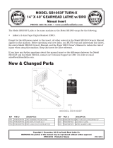
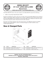
The Model SB1269 taper attachment was
designed to fit onto a series of South Bend
lathes. Shown in Figure 1, is a Model SB1012
lathe that is fitted with the Model SB1269 taper
attachment.
Figure 1. Model SB1269 installed.
Taper attachment installed
on rear side of lathe
Introduction
If you need help with your new item, contact
us at: (360) 734-1540 • FAX: (360) 676-1075
This taper attachment mounts quickly to the
back bed way of your lathe. Accurate tapers of up
to 12" can be produced without repositioning the
attachment or having to offset the talstock.
The Model SB1269 features scales at both ends,
reading inches-per-foot and degrees. An angle
adjusting knob with fine threads achieves
exacting control when setting tapers.
Another feature is the ability to use the taper
attachment without disengaging the cross slide
nut. This design allows the taper attachment to
be functional at any time by simply tightening
the two deadman-clamp cap screws, which lock
the deadman-clamp to the rear lathe way.
Specifications

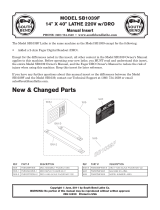
Identification
Serious personal injury could occur if you
connect the lathe to power before completing
the installation process. DO NOT connect
power until instructed to do so later in this
manual.
Untrained users have an increased risk of
seriously injuring themselves with this lathe
accessory. Do not operate lathe until you have
understood this entire manual and received
proper training.
Dead Man
Arm
Taper
Knob
Taper
Scale
Dead Man
Clamp
Travel
Stop
Dovetail
Gib
Gib
Adjustment
Screws
Main
Housing
Table
Way
Arm Clevis
Figure 2. Identification.
-2-
For Product Mfg. Since 1/10
Model SB1269
INTRODUCTION

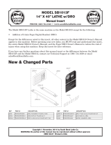
Inventory
When you are completely satisfied with the
condition of your shipment, you should inventory
the contents.
Inventory (Figure 3) Qty
A. Cap Screws M10-1.5 x 40mm
(Taper Attachment Mounting) ......................4
B. Taper Attachment Assembly .........................1
C. Tapered Pins 8.7 x 7.7 x 47mm .....................2
D. Copper Anti-Score Plug .................................1
E. Deadman Clamp Assembly ........................... 1
F. Deadman Arm and Clevis .............................1
Unpacking
This item was carefully packaged to prevent
damage during transport. If you discover any
damage, please immediately call Customer
Service at (360) 734-1540 for advice. You may
need to file a freight claim, so save the containers
and all packing materials for possible inspection
by the carrier or its agent.
Figure 3. Model SB1269 inventory.
A
B
C
D
E
F
Things You'll Need
This attachment is intended to be a permanent
installation. Installation will take approximately
1.2 hours and require the following items:
For Assembly
• Cotton Rags
• Mineral Spirits
• SafetyGlasses
• Oil Can with any Basic Machine Oil
• Assistant
• Open End Wrench (17mm)
• Hex Wrenches (3, 4, 5, 6, and 8mm)
• Tapered Drill Bit (8mm)
• SafetyGlasses
• Oil Can with Pressure Tip
• Dila Indicator with Magnetic Base
• Phillips Screwdriver, #2
• Hammer
• Drill Bit,
19
⁄64"
• Spiral Pin Reamer, Industrial Size: 6
—Small End Diameter: 0.2773"
—Large End Diameter: 0.3540"
For Product Mfg. Since 1/10 Model SB1269
-3-
PREPARATION

The unpainted surfaces are coated with a heavy-
duty rust preventative that prevents corrosion
during shipment and storage.
This rust preventative has been a close ally
and guardian since this item left the factory.
If the unpainted surfaces are free of rust, then
be thankful that the rust preventative did its
job...and try to stay thankful as you clean it off,
because it can be challenging to remove if you are
unprepared and impatient.
Plan on spending time cleaning and removing
the rust preventative. The time you spend doing
this will reward you with smooth sliding parts
and a better appreciation for the proper care of
the unpainted surfaces.
Although there are many ways to successfully
remove the rust preventative, these instructions
walk you through what works well for us.
Before cleaning, gather the following:
• DisposableRags
• Cleaner/degreaser
• Safetyglasses&disposablegloves
Note: Automotive degreasers, mineral spirits
orWD•40canbeusedtoremoverust
preventative. Before using these products,
though, test them on an unnoticeable area
of a painted area to make sure they will not
damage it.
Basic steps for removing rust preventative:
1. Put on safety glasses and disposable gloves.
2. Coatallsurfacesthathaverustpreventative
with a liberal amount of your cleaner or
degreaser and let them soak for few minutes.
3. Wipe off the surfaces. If your cleaner or
degreaser is effective, the rust preventative
will wipe off easily.
Note: To clean off thick coats of rust preventative
on flat surfaces, such as beds or tables, use
aPLASTICpaintscrapertoscrapeoffthe
majority of the coating before wiping it off
withyourrag.(Donotuseametalscraperor
it may cause scratches.)
4. RepeatSteps 2–3 as necessary until clean,
then coat all unpainted surfaces with a
quality metal protectant to prevent rust.
GAS
Gasoline and petroleum
products have low flash
points and can explode
or cause fire if used for
cleaning. Avoid using these
products to remove rest
preventative.
Many cleaning solvents are
toxic if inhaled. Minimize
your risk by only using
these products in a well
ventilated area.
Avoid chlorine-based solvents, such as
acetone or brake parts cleaner that may
damage painted surfaces. Always follow the
manufacturer’s instructions when using any
type of cleaning product.
Cleaning & Protecting
-4-
For Product Mfg. Since 1/10
Model SB1269
PREPARATION

Installation
To install the taper attachment:
1. DISCONNECT LATHE FROM POWER!
2. With the assistance of a helper and using
a 6mm hex wrench, remove the four cap
screws holding the splash guard on the rear
of the lathe.
3. Using a 5mm hex wrench, remove the two
leadscrew end-cap cap screws shown in
Figure 4.
Note: Make sure to keep the correct race with
its original bearing, and do not hammer on
the casting or chisel the inner races out. The
inner race has a loose fit. If it is difficult to
remove from its seat, be patient and spray
some penetrating oil into the bore and
carefully work the race out from the grease
suction that is holding it. You can also soak
the casting in mineral spirits to break this
suction.
7. Using a #2 Phillips screwdriver, remove
the eight flat head screws and the taper
attachment top plate (Figure 6).
Figure 6. Top plate removal.
8. Using a 5mm hex wrench, loosen the slide
block set screw, as shown in Figure 7.
Figure 7. Slide block removal.
Figure 4. Lead screw end-cap.
Lock
Nut
Set
Screws
Leadscrew
End-Cap
Set
Screws
Cap
Screws
4. Using a 3mm hex wrench, remove the four
set screws (Figure 4) from the saddle.
5. Using a 17mm wrench, remove the lock nut
(Figure 4) from the end of the lead screw.
6. Slide the end-cap off the lead screw. Make
sure that the inner and outer race shown in
Figure 4 do not stick to the end-cap.
Figure 5. End-cap removal.
Inner
Race
Outer
Race
End
Cap
For Product Mfg. Since 1/10 Model SB1269
-5-
PREPARATION

9. Lift out the slide block without losing the
copper anti-score plug (Figure 8).
12. Clean the bearings and races with mineral
spirits, then dry and repack them with white
lithium grease.
13. Install the bearings and races onto the
leadscrew in the order shown in Figure 10.
Figure 8. Slide block copper anti-score plug.
10. Apply a dab of multi-purpose grease to the
copper plug to prevent it from falling out
when handling the slide block.
Note: This copper plug prevents the set screw
from scoring the main pivot pin when the
taper attachment is being used.
11. Using a 5mm hex wrench, remove the two
cap screws that retain the slide block, and
remove the slide block end-cap as shown in
Figure 9.
Copper
Anti-Score
Plug
Figure 9. Slide block end-cap removal.
Slide
Block
End
Cap
14. Using a 17mm wrench, thread the lock nut
onto the lead screw until the bearings are
slightly preloaded, and the slide-block end
cap has zero end play.
15. Using a 5mm hex wrench, secure the
slide block onto the endcap with the two
previously removed cap screws, as shown in
Figure 11.
Figure 10. Slide block end-cap installation,
(bearings shown without grease for clarity).
Bearing
Races
Bearing and
Race Orientation
is the Same as
Shown to the Left
16. Pull or push the cross slide assembly so the
center of the pivot pin bore is 4
1
⁄2" from the
carriage face, as shown in Figure 11.
Figure 11. Slide block installation.
End Cap
4
1
⁄
2
"
Slide Block
-6-
For Product Mfg. Since 1/10
Model SB1269
PREPARATION

Figure 15. Top plate installation.
22. Reinstall the top plate as shown in Figure
15.
17. Make sure the copper plug is still inside of
the slide block.
18. With the help of an assistant, raise the taper
attachment underneath the slide block, so
the pivot pin slides into the pin bore in the
slide block (see Figure 12).
19. With your assistant aligning the taper
attachment mounting holes, use an 8mm
hex wrench to tighten the four mounting cap
screws and secure the taper attachment to
the carriage face (see Figure 12).
20. Using a 4mm hex wrench, snug the slide
block set screw so the copper plug is slightly
preloaded against the pivot pin (see Figure
13).
Figure 12. Taper attachment installation.
Mounting
Cap Screw
Figure 13. Pin adjustment.
Pivot Pin
Pin and Pin
Bore
21. Apply drops of oil liberally at all four way oil
ports, both slide block ways, and the pivot
pin shown in Figure 14.
Figure 14. Lubrication locations.
Ball
Oilers
Slide Block Ways
Pivot Pin
Ball
Oilers
23. Slide the deadman clamp onto the lathe
way, thread the arm clevis into the taper
attachment, and then slide the arm clamp
onto the deadman arm, as shown in Figure
16. Do not tighten the mounting cap screws
or arm clevis at this time.
For Product Mfg. Since 1/10 Model SB1269
-7-
PREPARATION

Figure 16. Deadman and arm installation.
Deadman
Clamp Cap
Screw
Deadman
Arm
Arm
Clevis
Arm Clamp
Cap Screw
29. Rotate, push in, or pull out the adjustment
cam to adjust the deadman arm so it is as
parallel as possible with the lathe bed in
both the vertical and horizontal plane.
Note: You may have to rotate the deadman arm
so the arm clevis allows the arm to be tilted
in a particular direction.
— To tilt the arm in the vertical plane, rotate
the knurled adjustment cam.
— To tilt the arm in the horizontal plane, slide
the adjustment cam in or out of the deadman
housings.
Figure 18. Saddle gap.
Complete Travel Without
Deadman Clamp Contact
1" Saddle
Safety Gap
28. Using a 3mm hex wrench, loosen the four
locking set screws (Figure 19) that lock the
adjustment cam in position.
24. Using a 6mm hex wrench, loosen the
dovetail lock cap screw at each end of the
taper attachment, as shown in Figure 17.
Figure 19. Deadman arm alignment.
Four Locking
Set Screws
Adjustment
Cam
Clevis
Jam Nut
Figure 17. Taper angle adjustment.
Dovetail Lock
Cap Screw
Taper Angle
Control Knob
Scale
25. Turn the taper angle control knob (Figure
17), so the taper attachment points to zero
degrees as shown on the scale.
26. Re-tighten both dovetail lock cap screws.
27. Slide the deadman clamp along the lathe
way to a position where the saddle will not
contact the clamp when cutting tapers.
There should be approximately 1" of safety
clearance or "saddle safety gap," as shown
in Figure 18. You must double check this
clearance to prevent a deadman clamp
carriage crash.
-8-
For Product Mfg. Since 1/10
Model SB1269
PREPARATION

35. Loosen the four mounting cap screws and
rotate the taper attachment left or right to
correct the alignment (see Figure 21).
Figure 22. Roll pin installation.
Pre-Drilled 6.5mm
Pilot Holes for
Tapered Pins
36. Retighten the taper attachment cap screws,
and double check your parallelism.
37. Using the existing pilot holes in the taper
attachment housing as guides (see Figure
22), drill out both holes with a
19
⁄64" drill bit,
and ream both holes with an industrial size
#6 spiral pin reamer deep enough so the
tapered pins fit flush. If you need to remove
the tapered pins for any reason, the internal
pin threads are a metric M6-1.
38. Position and tap-in the tapered pins, so they
will permanently lock the taper attachment
in the current alignment position.
39. Reinstall the lathe splash guard.
33. Setup a knob indicator as shown in Figure
20, so the knob indicator point is against the
top of the dovetailed table.
34. Move the carriage to the other end of the
way, read the knob indicator, and note the
amount of total misalignment in parallelism
between the path of the carriage and the
path of the taper attachment.
— If the knob indicator readings show a tilt
of 0.025" or less between the two extreme
positions of the taper attachment, then the
alignmentisacceptable.GotogotoStep 37.
— If the parallelism is greater than 0.025",
proceed to Step 35.
30. Using a 3mm hex wrench, tighten the
cam set screws and the clevis jam nut (see
Figure 16) when finished.
31. Using 8mm and 6mm hex wrenches, tighten
the deadman clamp and the arm clamp cap
screws, as shown in Figure 18.
32. Move the carriage so the taper attachment
stops completely at the forward-most
position, as shown Figure 20.
Figure 20. Taper attachment alignment.
Figure 21. Parallelism correction.
Rotate Slightly
to Align
For Product Mfg. Since 1/10 Model SB1269
-9-
PREPARATION

Operation
6. Retighten both dovetail lock cap screws.
7. Begin lathe operations.
When the deadman clamp cap screws are loose,
the deadman clamp slides along the lathe way,
and the taper attachment is disengaged. Normal
lathe turning operations can be conducted.
When the deadman clamp cap screws are
tightened, the deadman clamp is locked to the
lathe way, and the taper attachment is engaged.
At this point tapered turning operations can be
made.
To use the taper attachment:
1. DISCONNECT LATHE FROM POWER!
2. Move the carriage, cross slide, and
compound rest so your turning bit is at your
needed location to begin the tapered cut.
3. Using an 8mm hex wrench, tighten both
deadman cap screws so the deadman clamps
against the lathe bedway, as shown in
Figure 23.
4. Using a 6mm hex wrench, loosen the dovetail
lock cap screw at each end of the taper
attachment, as shown in Figure 24.
Figure 24. Taper angle control knob.
Dovetail
Lock Cap
Screw
Taper Angle Control Knob
0
Taper Angle
1
Taper Per/Inch
One inch long tapered
workpiece such as an arbor or pin.
Figure 25. Scale relationship with workpiece.
Figure 23. Deadman clamp location.
Cap Screw
5. Turn the taper angle control knob (see
Figure 24) until you reach the taper angle
or the taper-per-inch setting that you need.
Refer to Figure 25 to select which scale best
suits your needs.
-10-
For Product Mfg. Since 1/10
Model SB1269
OPERATION

To disable the taper attachment:
1. DISCONNECT LATHE FROM POWER!
2. Use an 8mm hex wrench, and loosen both
deadman clamp cap screws shown in Figure
26, so the deadman can slide on the way as
the carriage is moved.
Figure 27. Taper angle control knob.
Dovetail
Lock Cap
Screw
Taper Angle Control Knob
3. Using a 6mm hex wrench, loosen both
dovetail lock cap screws (one end shown in
Figure 27).
Figure 26. Deadman clamp location.
Cap Screw
4. Turn the taper angle control knob until you
reach "0" as indicated by the taper scale.
5. Using a 6mm hex wrench, tighten both
dovetail lock cap screws.
For Product Mfg. Since 1/10 Model SB1269
-11-
MAINTENANCE

3. Using an oil can with the same oil you use
on your lathe ball oilers, apply oil on the
knob threads shown in Figure 30.
To clean the taper attachment:
1. DISCONNECT LATHE FROM POWER!
2. Vacuum excess metal chips and wipe off the
remaining metal, coolant, and oils with a
dry cloth.
If any coolant sludge has built up, use
mineral spirits to remove, and then
relubricate with the same oil you use on
your lathe to prevent surface rust.
Figure 30. Lubrication locations.
Knob Threads
Figure 29. Lubrication locations.
Slide Block Ways
Pivot Pin
Slide Block Ways
Figure 28. Lubrication locations.
Ball Oilers
Maintenance Schedule
For optimum performance from your taper
attachment, follow this maintenance schedule
and refer to any specific instructions given in this
section.
Daily:
• Check/correctloosemountingbolts.
• Clean/protect table.
• Cleanmetalchipsand coolant residue from
all surfaces.
• Lubricate ball oilers.
• Correct any other unsafe condition.
Monthly:
• Lubricate pivot pin and slide block ways.
To lubricate the taper attachment:
1. DISCONNECT LATHE FROM POWER!
2. Using an oil can with the same oil you use on
your lathe ball oilers, apply liberal amounts
of oil to the four ball oilers, the pivot pin,
and the dovetail surface shown in Figures
28–30.
Always disconnect
machine from power before
performing maintenance or
serious personal injury may
result.
!
-12-
For Product Mfg. Since 1/10
Model SB1269
MAINTENANCE

2
9
8
7
3
33
32
31
30
28
12
13
5
2
21
20
18
17
16
15
14
12
13
12
11
10
34
35
27
26
36
25
22
24
36
23
19
20
51
10
11
48
46
47
33
45
44
43
40
42
40
39
38
37
23
41
46
49
50
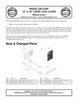
Taper Attachment Breakdown
For Product Mfg. Since 1/10 Model SB1269
-13-
PARTS

REF PART # DESCRIPTION REF PART # DESCRIPTION
2 PCAP02M CAP SCREW M6-1 X 20 28 PSB1269028 PIN
3 PSB1269003 BALL OILER 30 PSB1269030 PIVOT SADDLE
5 PSB1269005 END CAP 31 PSB1269031 GIB
7 PFH04M FLAT HD SCR M6-1 X 8 32 PSB1269032 GIB SCREW
8 PSB1269008 COVER PLATE 33 PCAP31M CAP SCREW M8-1.25 X 25
9 PSB1269009 SLIDE BLOCK 34 PSB1269034 DOVETAIL
10 PSB1269010 COPPER PIN 35 PCAP06M CAP SCREW M6-1 X 25
11 PSS06M SET SCREW M8-1.25 X 16 36 PCAP14M CAP SCREW M8-1.25 X 20
12 PCAP45M CAP SCREW M8-1.25 X 45 37 PSB1269037 COTTER PIN 4.5 X 30MM
13 PSB1269013 TAPERED PIN 38 PSB1269038 CLEVIS
14 PSB1269014 MAIN HOUSING 39 PSB1269039 CLEVIS PIN
15 PSB1269015 PLATE 40 PSB1269040 NUT BLOCK M6-1 X 25
16 PS68M PHLP HD SCR M6-1 X 10 41 PSB1269041 T-NUT M8-1.25
17 PSS21M SET SCREW M8-1.25 X 25 42 PSB1269042 NUT BLOCK
18 PN03M HEX NUT M8-1.25 43 PSB1269043 LEADSCREW
19 PCAP13M CAP SCREW M8-1.25 X 30 44 PSB1269044 KNOB
20 PSB1269020 STAINLESS RIVET 45 PSB1269045 DEADMAN ARM
21 PSB1269021 SCALE TAPER-PER-INCH 46 PSS04M SET SCREW M6-1 X 12
22 PSB1269022 SCALE DEGREE 47 PSB1269047 ARM CLAMP
23 PSB1269023 STOP 48 PSB1269048 ECCENTRIC CAM
24 PSB1269024 TABLE 49 PCAP143M CAP SCREW M10- 1.5 X 50
25 PSB1269025 T-NUT M8-1.25 50 PSB1269050 DEADMAN CLAMP
26 PSB1269026 GIB 51 PSB1269051 PLATE
27 PCAP07M CAP SCREW M6-1 X 30
Parts List
-14-
For Product Mfg. Since 1/10
Model SB1269
PARTS

WARRANTY & RETURNS
This quality product is warranted by South Bend Lathe Company to the original buyer for one year
from the date of purchase. This warranty does not apply to consumable parts, or defects due to any
kind of misuse, abuse, negligence, accidents, repairs, alterations or lack of maintenance. We do not
reimburse for third party repairs. In no event shall we be liable for death, injuries to persons or
property, or for incidental, contingent, special or consequential damages arising from the use of our
products.
We do not warrant or represent that this machine complies with the provisions of any law, act, code,
regulation, or standard of any domestic or foreign government, industry, or authority. In no event
shall South Bend’s liability under this warranty exceed the original purchase price paid for this
machine. Any legal actions brought against South Bend Lathe Company shall be tried in the State of
Washington, County of Whatcom.
This is the sole written warranty for this machine. Any and all warranties that may be implied by
law, including any merchantability or fitness, for any purpose, are hereby limited to the duration of
this warranty. To take advantage of this warranty, contact us by mail or phone to give us the details
of the problem you are having.
Thank you for your business and continued support.
WARRANTY

Copyright © February, 2010 By South Bend Lathe Co. Revised April, 2010 (CR).
WARNING: No portion of this manual may be reproduced in any shape or form
without the written approval of South Bend Lathe Co.
#CR12550 Printed in Taiwan.
www.southbendlathe.com
/