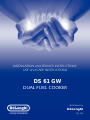
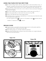
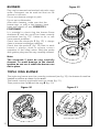
DeLonghi DS 61 GW is a dual fuel cooker with both gas and electric hobs, allowing you to choose the most suitable cooking method for each dish. The gas burners provide instant heat and precise temperature control, while the electric hobs offer a more consistent and even heat distribution. The oven has multiple cooking functions, including grilling, baking, and roasting, making it suitable for a wide range of dishes. It also features a defrost function for quickly thawing frozen foods. Additionally, the cooker has a spacious storage drawer for pots, pans, and other kitchen accessories.
DeLonghi DS 61 GW is a dual fuel cooker with both gas and electric hobs, allowing you to choose the most suitable cooking method for each dish. The gas burners provide instant heat and precise temperature control, while the electric hobs offer a more consistent and even heat distribution. The oven has multiple cooking functions, including grilling, baking, and roasting, making it suitable for a wide range of dishes. It also features a defrost function for quickly thawing frozen foods. Additionally, the cooker has a spacious storage drawer for pots, pans, and other kitchen accessories.


-
 1
1
-
 2
2
-
 3
3
-
 4
4
-
 5
5
-
 6
6
-
 7
7
-
 8
8
-
 9
9
-
 10
10
-
 11
11
-
 12
12
-
 13
13
-
 14
14
-
 15
15
-
 16
16
-
 17
17
-
 18
18
-
 19
19
-
 20
20
-
 21
21
-
 22
22
-
 23
23
-
 24
24
-
 25
25
-
 26
26
-
 27
27
-
 28
28
-
 29
29
-
 30
30
-
 31
31
-
 32
32
-
 33
33
-
 34
34
-
 35
35
-
 36
36
-
 37
37
-
 38
38
-
 39
39
-
 40
40


DeLonghi DS 61 GW is a dual fuel cooker with both gas and electric hobs, allowing you to choose the most suitable cooking method for each dish. The gas burners provide instant heat and precise temperature control, while the electric hobs offer a more consistent and even heat distribution. The oven has multiple cooking functions, including grilling, baking, and roasting, making it suitable for a wide range of dishes. It also features a defrost function for quickly thawing frozen foods. Additionally, the cooker has a spacious storage drawer for pots, pans, and other kitchen accessories.
Ask a question and I''ll find the answer in the document
Finding information in a document is now easier with AI
Related papers
Other documents
-
 Cozy Products CL-COOP Specification
-
CDA DC930 Series User manual
-
-
-
Smeg Plate TBX6090 User manual
-
Euro Appliances EO90FSDPBL User guide
-
CDA RC 9000 Users operating instructions User manual
-
EURO EG900GDCRM Operating instructions
-
Technika TEG75U User manual
-
