Page is loading ...

DVL Insert EF II
Owner's Manual
Featuring the
Burner
Tested and Listed by
OMNI-Test Laboratories, Inc.
Beaverton, Oregon
Report # 028-F-72-5
ANSI Z21.88
• Direct Vent Fireplace Insert
• Masonry or Factory Built (Metal)
Wood-Burning Fireplace
• Residential or Mobile Home
WARNING: If the information in these instructions is not followed exactly, a fire or
explosion may result causing property damage, personal injury or loss of life.
- Do not store or use gasoline or other flammable vapors and liquids in the vicinity of this or
any other appliance.
WHAT TO DO IF YOU SMELL GAS
• Do not try to light any appliance.
• Do not touch any electrical switch; do not use any phone in your building.
• Immediately call gas supplier from a neighbor's phone. Follow the gas supplier's
instructions.
• If you cannot reach your gas supplier, call the fire department.
- Installation and service must be performed by a qualified installer, service agency or the
gas supplier.
This appliance may be installed as an OEM installation in a manufactured (mobile) home and must be
installed in accordance with the manufacturer’s instructions and the manufactured home construction
and safety standard, Title 24 CFR, Part 3280.
This appliance is only for use with the type(s) of gas indicated on the rating plate. A conversion kit is
supplied with the appliance.
Installer: After installation give this manual to the home-owner and
explain operation of this heater.
Copyright 2008, T.I. $10.00 100-01174_002 4080123
Travis Industries, Inc.
4800 Harbour Pointe Blvd. SW
Mukilteo, WA 98275

2 Introduction
© Travis Industries 4080123 100-01174_002
Introduction
We welcome you as a new owner of a DVL Insert. In purchasing this fireplace insert you have
joined the growing ranks of concerned individuals whose selection of an energy system reflects
both a concern for the environment and aesthetics. It is one of the finest home heaters the world
over. This manual will explain the installation, operation, and maintenance of this heater. Please
familiarize yourself with the Owner's Manual before operating your heater and save the manual for
future reference. Included are helpful hints and suggestions that will make the operation and
maintenance of your new heater an easier and more enjoyable experience. We offer our continual
support and guidance to help you achieve the maximum benefit and enjoyment from your heater.
Important Information
No other DVL Insert has the same serial number as
yours. The serial number is below and to the left of
the gas control valve.
This serial number will be needed in case you
require service of any type.
Model: DVL Insert EF II
Serial Number:
Purchase Date:
Purchased From:
Register your warranty online at:
traviswarranty.com
Or, mail your warranty card to:
Travis Industries House of Fire
4800 Harbour Pointe Blvd. SW
Mukilteo, WA 98275
Save Your Bill of Sale.
To receive full warranty coverage, you will
need to show evidence of the date you
purchased your heater. Do not mail your
Bill of Sale to us.
We suggest that you attach your Bill of
Sale to this page so that you will have all
the information you need in one place
should the need for service or information
occur.

Table of Contents 3
© Travis Industries 4080123 100-01174_002
Introduction and Important Information
Introduction......................................................2
Safety Precautions
Safety Precautions............................................4
Features & Specifications
Features..........................................................6
Installation Options............................................6
Heating Specifications .......................................6
Dimensions......................................................6
Installation
Installation Warnings .........................................7
Packing List......................................................7
Additional Items Required...................................7
Items Packed with the Face................................7
Order of Installation...........................................7
Top Convection Deflector...................................8
Fireplace Requirements .....................................8
Factory-Built (Metal) Wood-Burning Fireplace
Requirements...............................................9
Hearth Requirements.........................................9
Clearances.......................................................10
Mantel Clearances.........................................10
Face Sizing ......................................................11
Gas Line Requirements......................................12
Gas Line Location .........................................12
Gas Inlet Pressure ........................................12
Vent Requirements............................................13
Altitude Considerations ..................................13
Vent Restrictor .............................................14
Vent Installation............................................14
Vent Location...............................................15
Vent Configurations.......................................15
Vent Connector Removal and Installation...........16
Installation Without Surround Panels....................18
Surround Panel Installation .................................18
Installation of the On/Off Switch and Rheostat....19
Electrical Connection.........................................19
Finalizing the Installation
Glass Frame Removal and Installation.................20
Log Set Installation............................................22
Steps for Finalizing the Installation.......................24
Pilot Flame Inspection .......................................24
Air Shutter Adjustment.......................................24
Operation
Before You Begin..............................................26
Location of Controls ..........................................26
Starting The Pilot Flame.....................................27
Starting the Heater for the First Time ...................28
Turning the Heater On and Off ............................28
Adjusting the Flame Height.................................28
Adjusting the Blower Speed.................................29
Normal Operating Sounds...................................29
Normal Operating Odors.....................................29
Maintenance
Maintaining Your Heater's Appearance .................30
Yearly Service Procedure...................................30
Troubleshooting Table ........................................31
How this Heater Works.......................................32
Wiring Diagram.................................................33
Replacement Parts List......................................33
Safety Label
Safety Label .....................................................34
Warranty
Warranty .........................................................35
Optional Equipment
LP Conversion Instructions.................................36
Firebacks.........................................................39
Accent Light.....................................................41
Lower Surround Panel.........................................43
Index
Index...............................................................46

4 Safety Precautions
© Travis Industries 4080123 100-01174_002
IF YOU SMELL GAS:
* Do not light any appliance
* Extinguish any open flame
* Do not touch any electrical switch or plug or unplug anything
* Open windows and vacate building
* Call gas supplier from neighbor's house, if not reached, call fire department
This unit must be installed b
y
a qualified installer to prevent the possibilit
y
of an
explosion. Your dealer will know the requirements in your area and can inform you
of those people considered qualified. The room heater should be inspected and
cleaned before use and at least annually by a qualified service person. More
frequent cleaning may be required due to excessive lint from carpeting, bedding
material, etc.
The instructions in this manual must be strictl
y
adhered to. Do not use makeshift
methods or compromise in the installation. Improper installation will void the
warrant
y
and safet
y
listin
g
.
For LPG only | Pout 11” W.C.
Look for this label:
If the label is present, the
heater is equipped for LP
(propane). If the label is
absent, the heater is equipped
for NG (natural gas).
This heater is either approved for natural
gas (NG) or for propane (LP). Burning the
incorrect fuel will void the warranty and
safety listing and may cause an extreme
safety hazard. Direct questions about the
type of fuel used to your dealer. Check the
label and flame adjust knob on the gas
control valve.
Ok
Contact
y
our local buildin
g
officials to obtain a permit and
information on any installation
restrictions or inspection
requirements in your area.
Notify your insurance
company of this heater as
well.
If the flame becomes soot
y
,
dark orange in color, or
extremely tall, do not operate
the heater. Call your dealer
and arrange for proper
servicing.
It is imperative that control
compartments, screens, or
circulating air passageways of
the heater be kept clean and
free of obstructions. These
areas provide the air necessary
for safe operation.
?
Do not operate the heater if it is
not operating properly in any
fashion or if you are uncertain.
Call your dealer for a full
explanation of your heater and
what to expect.
Gas
Do not store or use
g
asoline or
other flammable liquids in the
vicinity of this heater.
Do not operate if an
y
portion of
the heater was submerged in
water or if an
y
corrosion occurs.
Immediately call a qualified
service technician to inspect
the appliance and to replace
any part of the control system
and any gas control wash has
been under water.

Safety Precautions 5
© Travis Industries 4080123 100-01174_002
Do not place clothin
g
or other
flammable items on or near
the heater. Because this
heater can be controlled by a
thermostat there is a possibility
of the heater turning on and
igniting any items placed on
or near it.
Li
g
ht the heater usin
g
the built-
in piezo igniter. Do not use
matches or any other external
device to light your heater.
Allow the heater to cool before
carrying out any maintenance
or cleaning.
The viewin
g
g
lass should be
opened only for lighting the
pilot or conducting service. Do
not operate with cracked,
broken, or removed glass.
An
y
safet
y
screen or
g
uard
removed for servicing must be
replaced prior to operating the
heater.
Never remove, replace, modify
or substitute any part of the
heater unless instructions are
given in this manual. All other
work must be done by a trained
technician. Don't modify or
replace orifices.
Operate the heater accordin
g
to the instructions included in
this manual.
If the main burners do not start
correctly turn the gas off at the
gas control valve and call your
dealer for service.
The pilot flame must contact
the thermopile and
thermocouple (see the
illustration to the left). If it does
not, turn the gas control valve
to "OFF" and call your dealer.
This unit is not for use with
solid fuel
Do not place an
y
thin
g
inside
the firebox (except the
included fiber logs).
If the fiber lo
g
s become
damaged, replace with Travis
Industries log set.
This
Manual
Do not throw this manual awa
y
.
This manual has important
operating and maintenance
instructions that you will need
at a later time. Always follow
the instructions in this manual.
Children and adults should be
alerted to the hazards of high
surface temperature and
should stay away to avoid
burns or clothing ignition.
Young children should be
supervised when they are in
the same room as the heater.
Plug the heater into a 120V
grounded electrical outlet. Do
not remove the grounding plug.
Don’t route the electrical cord
in front of, over, or under the
heater
Instruct ever
y
one in the house
how to shut gas off to the
appliance and at the gas main
shutoff valve. The gas main
shutoff valve is usually next to
the gas meter or propane tank
and requires a wrench to shut
off.
Travis Industries, Inc.
g
rants
no warranty, implied or stated,
for the installation or
maintenance of your heater,
and assumes no
responsibility of any
consequential damage(s).

6 Features and Specifications
© Travis Industries 4080123 100-01174_002
Features
• Works During Power Outages (millivolt system)
• High Efficiency
• Optional Thermostat or Remote Control
• Ember Fyre™ Burner for "Wood Fire" Look
• Quiet Blower for Effective Heat Distribution
• Convenient Operating Controls
• Variable-Rate Heat Output
• Low Maintenance
Installation Options
• Residential or Mobile Home
• Fireplace Insert
• Masonry or Factory Built (Metal) Wood-
Burning Fireplace
Heating Specifications
Natural Gas Propane
Approximate Heating Capacity (in square feet)* 600 to 2,000 600 to 2,000
Maximum BTU Input Per Hour 40,000 40,000
Minimum BTU Output on Low 20,300 19,700
Steady State Efficiency** (with blowers on) Up to 79.3 % Up to 81.2 %
AFUE (Annual Fuel Utilization Efficiency) Up to 71.7 % Up to 73.4 %
* Heating capacity will vary with floor plan, insulation, and outside temperature.
** Efficiency rating is a product of thermal efficiency rating determined under continuous
operation independent of installed system.
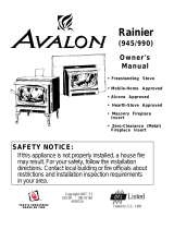
Dimensions
44-3/16"* 8x10 Arch/Rect. Panels
48-3/16"* 10x13 Rect. Panels
* Includes trim
NOTE: on older style panels the 3/8" standoffs
are no longer required and may be bent back.
20"
See the section "Vent Requirements"
for vent location.
14-1/2"*
1-1/4"*
33-3/8"* 8x10
Arch/Rect. Panels
36-3/8"* 10x13
Rect. Panels
31-1/2"
23-3/4"

Installation (for qualified installers only) 7
© Travis Industries 4080123 100-01174_002
Installation Warnings
• Failure to follow all of the requirements may result in property damage, bodily
injury, or even death.
• This heater must be installed by a qualified installer who has gone through a
training program for the installation of direct vent gas appliances.
• This appliance must be installed in accordance with all local codes, if any; if not,
follow ANSI Z223.1 and NFPA 54(88).
• In Manufactured or Mobile Homes must conform with Manufactured Home
Construction and Safety Standard, Title 24 CFR, Part 3280, or, when such a
standard is not applicable, the Standard for Manufactured Home Installations,
ANSI/NCSBCS A225.1. This appliance may be installed in Manufactured Housing
only after the home is site located.
• The heater is designed to operate on natural gas, or propane (LP).
• All exhaust gases must be vented outside the structure of the living-area.
Combustion air is drawn from outside the living-area structure.
• Notify your insurance company before hooking up this heater.
• The requirements listed below are divided into sections. All requirements must
be met simultaneously. The order of installation is not rigid – the qualified
installer should follow the procedure best suited for the installation.
Packing List
• Top Convection Deflector (with screws)
• Propane Conversion Kit
• Log Set
• "Fireplace Altered" tag (attach to the fireplace)
• FPX Face Brackets (see pg. 11 for details)
Additional Items Required
• Faceplate
• 6-5/8" to 3" & 4" Co-Linear Adapter - with flashing (Travis part # 98900124)
• 3" and 4" Diameter Gas Liner
• Direct Vent Cap (Simpson Duravent Part # 991)
• Gas Line Equipment (shutoff valve, pipe, etc.)
Items Packed with the Face
• Face with attachment hardware and cove covers (if necessary)
• Face Installation Instructions
Order of Installation
1 Install the Top Convection Deflector (see page 8).
2 If the heater is to use propane, install the propane conversion kit (see page 36).
3 Install gas line into the fireplace (do not connect to unit).
4 Position the heater.
5 Connect the gas line and gas vent to the appliance.
6 Install the optional surround panels and trim. Attach the on/off switch.
7 Follow the instructions under "Finalizing the Installation" on page 24.

8 Installation (for qualified installers only)
© Travis Industries 4080123 100-01174_002
Top Convection Deflector
Install the top convection deflector as shown to
the right.
The deflector is shipped on top of the insert.
The screws are shipped inside the owner's pack.
Fireplace Requirements
• Insert must be placed within a code-conforming masonry fireplace or tested and listed factory-
built (metal) wood-burning fireplace. Repair any fireplace damage prior to installation.
• Because the insert uses a circulation blower, clean the fireplace, smoke shelf, and chimney
prior to installation.
• This heater may be placed in a bedroom. Please be aware of the large amount of heat this
appliance produces when determining a location.
The DVL inserts 14-1/2" into the
fireplace.
Min. 31-1/2" - additional space may be required for gas line installation.
For tight fits (under 28"), see the section "Removing the Vent Connector"
See "Leveling Bolts" for details
on leveling the heater.
Min. 23-3/4"
The gas line and shutoff
valve should be installed
prior to insert placement.
Attach the "This fireplace has been altered..." plate
to the fireplace (use two screws or other suitable
method). You may wish to place it in a location
where it will be covered by the surround panels.

Installation (for qualified installers only) 9
© Travis Industries 4080123 100-01174_002
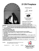
Factory-Built (Metal) Wood-Burning Fireplace Requirements
NOTE:Any parts that are removed must be removed in a way that would allow them to be re-installed if the
insert is ever removed.
The damper ("A") and grate (with log set) ("B") must be removed (see the illustration below)
The smoke shelf ("C"), internal baffles ("D"), screen ("E"), masonry lining or refractory ("G" & "I"), and metal
or glass doors ("F") may be removed (if applicable)
The fireplace must be permanently marked to
indicate that it has been altered and is no longer
suitable for burning solid fuel (wood), unless the
removed parts are re-installed. Cutting of any sheet
metal parts is prohibited (removal of rivets or screws
is acceptable).
The insulation ("H"), and any structured rigid frame
members must not be removed or altered (side and
top of door frame, side and top of the face of the
fireplace, metal sides, etc.).
The metal floor ("J") may be removed to allow
additional room for installation of the insert. If the
floor is removed the insert must be placed directly
on the metal base of the metal fireplace.
C
B
F
I
D
E
A
G
H
J
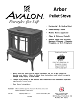
Hearth Requirements
The heater and face must not contact combustible surfaces. A non-combustible hearth extension
is not required. However, if the heater is installed next to the floor, we recommend a hearth to
protect the flooring surface from discoloration or other negative impact from the heater.
Leveling Bolts
This heater includes
front and rear leveling
bolts to accommodate
fireplaces with a step-
down firebox.
NOTE: To access the
rear leveling bolts,
remove the burner
(see page 39).
Use a 1/2” socket wrench
(with extension) to adjust
the leveling bolts.
To access the rear leveling bolts remove these
access plates (replace access plate and
gasket after adjustment).
Rear Leveling Bolt
Front Leveling Bolts

10 Installation (for qualified installers only)
© Travis Industries 4080123 100-01174_002
Clearances
Due to the high temperature of the heater, it should be located out of traffic and away from
furniture and draperies.
Side
Wall
Combustible or Non-Combustible Mantel
Combustible Top Facing
Non-Combustible
Facing
Minimum Clearances
k
l
m
n
x
Sidewall to Insert
Side Facing
Top Facing*
Mantel*
Extension onto Hearth
4"
4"
35-1/2"**
35-1/2"**
1-1/4"
l
k
x
n
m
* The non-combustible top facing must extend
35-1/2” above the base of the insert or to the
bottom of the mantel (whichever is less).
** Measured from the base of the insert.
Mantel Clearances
The maximum mantel depth is 12”.
NOTE: The combustible area above the facing must not protrude more than 3/4" from the facing.
If it does, it is considered a mantel and must meet the mantel requirements listed in this manual.
Maximum Mantel Depth
Mantel Height
Above Base of Insert (n)
37+”
34”
33”
32”
31”
0” 1” 2” 3” 4” 5” 6” 7” 8” 9” 10”11”
12”
35”
36”

Installation (for qualified installers only) 11
© Travis Industries 4080123 100-01174_002
Face Sizing
Face Height Width Notes
Rawhide 27” 35-3/4”
Victorian 27” 35-3/4”
Rosario 26” 35-3/4”
Cambridge 25-7/8” 37-5/8”
Craftsman 27-1/2” 36”
Bungalow 27” 32-3/4”
Classic Arched, Artisan 26-1/2” 34-3/4” Side begins arch 3-1/2” below top - 45” radius
Metropolitan 26-1/2” 34-3/4”
Architectural Series 27-7/8” 33-5/8”
Discovery 26’ 35-3/4’
Wilmington 27” 36-1/8”
Face Mounting Brackets – Arched, Artisan, Metropolitan, Victorian Lace
Some Arched, Artisan, Metropolitan and Victorian Lace Faces include old brackets that will not
mount to the heater (see illustration below). For these faces, make sure to use the new mounting
brackets (either included with the heater or available through your dealer - SKU 225-20054).
WARNING: When attaching the Victorian Lace Face, do not over-tighten the screws. Over-
tightening the screws may damage the face – simply tighten the screws until they contact the face.
New Brackets Old Brackets
Install the face mounting
brackets with the included nuts.
NOTE: The brackets install into the
lower pair of holes on the insert.
NOTE: The brackets
install with this pair of
closely spaced flanges at
the top.

12 Installation (for qualified installers only)
© Travis Industries 4080123 100-01174_002
Gas Line Requirements
MASSACHUSETTS INSTALLATIONS - WARNING:
THIS PRODUCT MUST BE INSTALLED BY A LICENSED PLUMBER OR GAS FITTER WHEN INSTALLED WITHIN THE
COMMONWEALTH OF MASSACHUSETTS.
OTHER MASSACHUSETTS CODE REQUIREMENTS:
• Flexible connector must not be longer than 36 inches.
• Shutoff valve must be a “T” handle gas cock.
• Only direct vent sealed combustion products are approved for bedrooms or bathrooms.
• Fireplace dampers must be removed or welded in the open position prior to the installation of a fireplace insert or gas log.
• A carbon monoxide (CO) detector is required in the same room as the appliance.
• The gas line must be installed in accordance with all local codes, if any; if not, follow ANSI 223.1 and the
requirements listed below.
• A manual shutoff valve is required within 3’ of the heater. It should be placed upstream of the flex line (if
used) and may be installed behind the access door inside the heater. ).
• The heater and gas control valve must be disconnected from the gas supply piping during any pressure
testing of that system at test pressures in excess of 1/2 psig. For pressures under 1/2 psig, isolate the
gas supply piping by closing the manual shutoff valve.
• Leak test all gas line joints and the gas control valve prior to and after starting the heater.
• This heater is designed either for natural gas or for propane (but not for both). Check the sticker on the top
of the gas control valve to make sure the correct fuel is used (see illustration on page 4).
• Installation must be performed by a qualified installer, service agency or the gas supplier (In Massachusetts
a licensed plumber/gasfitter).
Gas Line Location
The gas inlet
accepts a 1/2" MPT.
3-1/8"
Shutoff Valve (secured to
the fireplace insert)
Fireplace Opening
Gas Inlet Pressure
Standard Input Pressure
Natural Gas 7" W.C. (1.74 kPA)
Propane 13" W.C. (2.73 kPA)
• If the pressure is not sufficient, make sure the piping used is large enough, the supply regulator is
adequately adjusted, and the total gas load for the residence does not exceed the amount supplied.
• The supply regulator (the regulator that attaches directly to the residence inlet or to the propane tank) should
supply gas at the suggested input pressure listed above. Contact the local gas supplier if the regulator is at
an improper pressure.

Installation (for qualified installers only) 13
© Travis Industries 4080123 100-01174_002
Vent Requirements
• The gas appliance and vent system must be vented directly to the outside of the building, and
never be attached to a chimney serving a separate solid fuel or gas-burning appliance. Each
direct vent gas appliance must use it's own separate vent system.
• Make sure the exhaust pipe on the heater connects to the exhaust portion of the cap. The
illustrations below show how the flex liners should be attached.
• The exhaust vent must reline the entire length of the chimney and terminate above the
chimney top
• Be careful not to crimp or rupture the liner when bending it into chimney offsets
• When installed, the vent must meet all of the vent manufacturer's requirements
• Make sure to order the following:
4” UL 441 Gas Liner for Exhaust, 3” UL 441 Gas Liner for Air Inlet
6-5/8” to 3” & 4” Co-Linear Adapter & Flashing (Travis Part # 98900124).
Vertical Termination Cap (Dura-Vent pt # 991)
Max. Ht. 40'
Min. Ht. 8'
Inlet
(3" dia.)
Exhaust
(4" dia.)
Max. 2'
offset
Altitude Considerations
• This heater has been tested at altitudes ranging from sea level to 8,000 feet (2,400 M). In this testing we
have found that the heater, with its standard orifice, burns correctly with just an air shutter adjustment.
• Failure to adjust the air shutter properly may lead to improper combustion which can create a safety hazard.
Consult your dealer or installer if you suspect an improperly adjusted air shutter.

14 Installation (for qualified installers only)
© Travis Industries 4080123 100-01174_002
Vent Restrictor
WARNING: Restrictor adjustment should only be done by a qualified installer.
Only those installations determined to be over-drafting require this adjustment. The best indication
of over-drafting is a hyper-active flame pattern (flames that move too quickly). If the air shutter is
constricted, the flames become short and yellow, yet still very active. Over-drafting may affect the
pilot, but this is not the best way to determine over-drafting. Over-drafting is most likely in tall
venting configurations (especially if using an “Exhaust Only Re-Line”). Do not over-restrict the vent
(this leads to ghosting or lifting flames - reduce restrictor setting).
Remove the face.
To Adjust the Restrictor:
To Access the Restrictor:
This restrictor is in position 1
(factory setting).
This restrictor is in
position 2.
Adjustment
Bracket
To adjust, lift up on the
adjustment plate and push it back
(use pliers if necessary).
WARNING: Use a glove to protect
your hand from burns.
Adjustment
Plate
#1
#2
1
2
Determine a restrictor position. Start low (move
the restrictor a maximum two positions at a time)
and thoroughly test the heater before adjusting further.
Lift up the adjustment plate and move it so the correct notch falls
into the slot on the adjustment bracket.
#3
#4
#5
Vent Installation
Inlet (3”)
Exhaust (4”)
Inlet
Exhaust
Termination Cap
(Simpson Part # 991)
6-5/8” to 3” & 4” Co-
Linear Adapter
(Travis Part #
98900124)
3” dia. Gas Liner
4” dia. Gas Liner
Use hose-clamps
to secure the vent.
Alternative Method: use high-temperature
silicone and secure with screws.
Use hose-clamps to
secure the vent.
Alternative Method: use
high-temperature
silicone and secure with
screws.

Installation (for qualified installers only) 15
© Travis Industries 4080123 100-01174_002
Vent Location
• A vent restrictor is built into the appliance to adjust the flow rate of exhaust gases. This ensures
proper combustion for all vent configurations. Depending upon the vent configuration, you
may be required to adjust the restrictor position. The charts for acceptable vent configurations
detail the correct vent restrictor position.
2”
Center Line
Inlet (3” Dia.)
Exhaust (4” Dia.)
Fireplace
Opening
1-1/2”
4-1/2”
14-3/4”
5-1/8”
NOTE: Vent location changes based
upon restrictor position. Position # 1 is
shown to the right. Each restrictor
position moves the vent location forward
(toward the fireplace opening)
approximately 1/4”.
Vent Configurations
Z.C. (Metal) Wood-Burning Fireplace
Inlet & Exhaust Re-Line
Exhaust Only Re-Line
Direct Vent Cap
(part # 991)
Recommended Block-Off
Plate (non-combustible
metal and/or insulation).
Prevents odors from
chimney entering room.
6-5/8" to 3" & 4" Colinear
Adapter & Flashing
(Travis Part # 98900124)
A block-off plate must
seal the intake to the
chimney space. This
way air is drawn down
the chimney for
combustion air.
Block-Off Plate
(non-combustible
materials)
NOTE: You may use either re-line configuration with a masonry or zero-clearance fireplace.
Inlet
Masonry Fireplace
Any cracks or
damage inside the
chimney must be
repaired.
Exhaust
4" dia.
Gas Liner
Inlet
3" dia. Gas Liner
Exhaust
4" dia. Gas Liner

16 Installation (for qualified installers only)
© Travis Industries 4080123 100-01174_002
Vent Connector Removal and Installation
• The vent connector is shipped attached to the insert, but may be removed to facilitate tight
installations. See the directions below for installation.
1. Route the flex vent through the chimney from above (leave an extra 3' at the top). Make sure
the flex is thoroughly stretched.
2. Remove the vent connector and attach it to the flex vent (see the instructions on the following
page). NOTE: be careful of the anti-seize on the connector – it will stain clothing, etc.
3. Pull on the flex vent until the vent connector is at the same height as the insert. Temporarily
attach the flex vent to the top of the chimney (leave extra slack).
4. Slide the insert into place, guiding the vent connector into the guides on top of the insert.
5. Attach the vent connector to the appliance (see the following page for details).
6. Remove any excess slack in the flex line and attach the vent termination.
4
3
2
1
5
6
2

Installation (for qualified installers only) 17
© Travis Industries 4080123 100-01174_002
Vent Connector Removal and Installation (continued)
Vent Connector Removal
Slide the vent
connector to the
rear. It will
"snap" out.
Pull the vent connector
rod forward.
Vent Connector Installation
Attach the flex vent to
the vent connector.
Slide the insert
into place, lining
up these guides
with the edges of
the vent
connector.
Push the vent
connector rod in, lift
slightly, and line it up
so the tabs on the end
of the rod engage the
hooks on the vent
connector
Pull on the vent connector rod until the
vent connector snaps into place. Slide
the vent connector rod in to conceal it.
WARNING: The anti-seize on
the vent connector can stain
clothing, carpets, or other
items.

18 Installation (for qualified installers only)
© Travis Industries 4080123 100-01174_002
Installation Without Surround Panels
The insert may be installed without surround panels. Mount the on/off switch and rheostat to the
control panel under the burner pan (see “Installation of the On/Off Switch and Rheostat” on page 19).
Surround Panel Installation
PANEL SIZE WIDTH HEIGHT PART #
8" x 10" Rectangular 44-3/16" 33-3/8" 98500606
Arched (8” x 10”) 44-3/16" 33-3/8" 98500608
10” x 13” Rectangular 48-3/16" 36-3/8" 98500607
1 Follow the directions below to install the side panels.
Line up each side surround
panel and insert two screws from
the inside to secure in place.
5/16" Nutdriver
Pre-thread the holes on the surround
panels with the screws included in the
surround panel kit.
b
a
Run the rheostat wires,
on/off switch wires, and
power cord through the
access hole on the
insert
2 Follow the directions below to install the top panel.
Install the top panel so the
two tabs insert into the slots
on the side panels.
Top
Panel
Top Trim
"L" Bracket
Right Side Trim
Slot for on/off
switch and hole
for rheostat
NOTE:
These 3/8"
stand-offs are
not required
and may be
flattened.
The insulation included with the
panels may be discarded.
a
Construct the panel trim. Insert one leg of each "L"
bracket into the top and side trim piece. Align the
trim to form a precise corner, then tighten the two set
screws with a small standard screwdriver. Slide the
trim over the panels.
Tighten the set
screws from the back
side with a small
standard screwdriver
"L" Bracket
Right Side
Trim
Top Trim
b

Installation (for qualified installers only) 19
© Travis Industries 4080123 100-01174_002
Installation of the On/Off Switch and Rheostat
The on/off switch and rheostat may be installed in either the surround panels or control panel. See
the illustration below for installation details.
c
a
Disconnect the red and brown wires leading to the on/off switch.
Insert the wires through the rectangular mounting hole (on the
surround panel or control panel) and attach to the on/off switch.
The wires must attach to the top and bottom posts on one side of
the switch - it does not matter which wire is on top. Press the
switch into the rectangular hole until it locks into place.
WARNING:
Make sure the heater
is unpluged before
installing the rheostat.
Upper Right of Trim
(preferred)
Remove the knob and nut from the rheostat. Insert the
shaft on the rheostat through the circular hole (on the
surround panel or control panel). Secure with the nut.
Replace the knob.
Make sure the wires do not contact the burner pan or
other hot surfaces (secure with lock ties if necessary).
Control Panel
(next to gas control valve)
b
Electrical Connection
• Route the power cord out of the access hole on the right side of the appliance.
• Plug the power cord into a grounded 120 Volt outlet (do not remove the grounding pin).
• The electrical connection may also be made using the optional Wiring Kit (SKU 97200315).

20 Finalizing the Installation
© Travis Industries 4080123 100-01174_002
Glass Frame Removal and Installation
Warning: The appliance must be completely cool before removing the glass.
Warning: Do not strike or slam the glass.
Note: If using a Victorian Lace or Bungalow face, attach the arch covers after installing the glass.
Open the four latches holding the glass
frame in place (start with the two below
the glass) - follow the directions shown
to the right.
a
Glass Frame
Lift the glass frame up
and pull it forward to
remove.
NOTE:
You may need to lift the
glass frame while re-
attaching.
b
Re-Attaching the Glass Frame:
a) Hang the glass frame on the firebox.
b) While holding in place, attach the upper latches
(follow the instructions to the right in reverse).
c) Lift the glass frame slightly and attach the lower latches.
NOTE:
Replace the cove
covers for those faces
using them.
Twist 1/4 turn.
Top of
Firebox
Glass
The latch will then disengage
from the latch bracket.
Push in on
the latch.
Latch
/