Technical Reference Guide
HP Compaq 8200 Elite Series
Business Desktop Computers
Document Part Number: 656770-001
March 2011
This document provides information on the design, architecture, function,
and capabilities of the HP Compaq 8200 Elite Series Business Desktop
Computers. This information may be used by engineers, technicians,
administrators, or anyone needing detailed information on the products
covered.

© Copyright 2011 Hewlett-Packard Development Company, L.P.
The information contained herein is subject to change without notice. HP is not responsible for any omissions or
errors contained herein.
Microsoft, MS-DOS, Windows, Windows NT, Windows XP, Windows Vista, and Windows 7 are trademarks of
Microsoft Corporation in the U.S. and other countries.
Intel, Intel Core i3/i5/i7, Pentium Dual-Core, Intel Celeron, Intel vPro, and Intel Inside are trademarks of Intel
Corporation in the U.S. and in other countries.
Adobe, Acrobat, and Acrobat Reader are trademarks or registered trademarks of Adobe Systems Incorporated.
The only warranties for HP products and services are set forth in the express warranty statements accompanying
such products and services. Nothing herein should be construed as constituting an additional warranty. HP shall
not be liable for technical or editorial errors or omissions contained herein.
This document contains proprietary information that is protected by copyright. No part of this document may be
photocopied, reproduced, or translated to another language without the prior written consent of Hewlett-Packard
Company.
Technical Reference Guide
HP Compaq 8200 Elite Series Business Desktop Computers
First Edition (March 2011)
Document Part Number: 656770-001

Technical Reference Guide www.hp.com iii
Contents
1 Introduction
1.1 About this Guide . . . . . . . . . . . . . . . . . . . . . . . . . . . . . . . . . . . . . . . . . . . . . . . . . . . . . . . . . . . . . 1–1
1.1.1 Online Viewing . . . . . . . . . . . . . . . . . . . . . . . . . . . . . . . . . . . . . . . . . . . . . . . . . . . . . . . . . 1–1
1.1.2 Hardcopy . . . . . . . . . . . . . . . . . . . . . . . . . . . . . . . . . . . . . . . . . . . . . . . . . . . . . . . . . . . . . . 1–1
1.2 Additional Information Sources . . . . . . . . . . . . . . . . . . . . . . . . . . . . . . . . . . . . . . . . . . . . . . . . . 1–1
1.3 Serial Number . . . . . . . . . . . . . . . . . . . . . . . . . . . . . . . . . . . . . . . . . . . . . . . . . . . . . . . . . . . . . . . 1–2
1.4 Notational Conventions . . . . . . . . . . . . . . . . . . . . . . . . . . . . . . . . . . . . . . . . . . . . . . . . . . . . . . . . 1–2
1.5.1 Special Notices . . . . . . . . . . . . . . . . . . . . . . . . . . . . . . . . . . . . . . . . . . . . . . . . . . . . . . . . . . 1–2
1.5.2 Values. . . . . . . . . . . . . . . . . . . . . . . . . . . . . . . . . . . . . . . . . . . . . . . . . . . . . . . . . . . . . . . . . 1–2
1.5 Common Acronyms and Abbreviations . . . . . . . . . . . . . . . . . . . . . . . . . . . . . . . . . . . . . . . . . . . 1–3
2 System Overview
2.1 Introduction . . . . . . . . . . . . . . . . . . . . . . . . . . . . . . . . . . . . . . . . . . . . . . . . . . . . . . . . . . . . . . . . . 2–1
2.2 Features . . . . . . . . . . . . . . . . . . . . . . . . . . . . . . . . . . . . . . . . . . . . . . . . . . . . . . . . . . . . . . . . . . . . 2–2
2.3 System Architecture . . . . . . . . . . . . . . . . . . . . . . . . . . . . . . . . . . . . . . . . . . . . . . . . . . . . . . . . . . 2–4
2.3.1 Intel Processor Support . . . . . . . . . . . . . . . . . . . . . . . . . . . . . . . . . . . . . . . . . . . . . . . . . . . 2–6
2.3.2 Chipset . . . . . . . . . . . . . . . . . . . . . . . . . . . . . . . . . . . . . . . . . . . . . . . . . . . . . . . . . . . . . . . . 2–6
2.3.3 Support Components . . . . . . . . . . . . . . . . . . . . . . . . . . . . . . . . . . . . . . . . . . . . . . . . . . . . . 2–7
2.3.4 System Memory . . . . . . . . . . . . . . . . . . . . . . . . . . . . . . . . . . . . . . . . . . . . . . . . . . . . . . . . . 2–7
2.3.5 Mass Storage Accomodations . . . . . . . . . . . . . . . . . . . . . . . . . . . . . . . . . . . . . . . . . . . . . . 2–8
2.3.6 Legacy Input/Output Interfaces . . . . . . . . . . . . . . . . . . . . . . . . . . . . . . . . . . . . . . . . . . . . . 2–8
2.3.7 Universal Serial Bus Interface . . . . . . . . . . . . . . . . . . . . . . . . . . . . . . . . . . . . . . . . . . . . . . 2–8
2.3.8 Network Interface Controller . . . . . . . . . . . . . . . . . . . . . . . . . . . . . . . . . . . . . . . . . . . . . . . 2–8
2.3.9 Graphics Subsystem . . . . . . . . . . . . . . . . . . . . . . . . . . . . . . . . . . . . . . . . . . . . . . . . . . . . . . 2–9
2.3.10 Audio Subsystem . . . . . . . . . . . . . . . . . . . . . . . . . . . . . . . . . . . . . . . . . . . . . . . . . . . . . . . 2–9
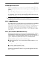
2.3.11 HP ProtectTools Embedded Security . . . . . . . . . . . . . . . . . . . . . . . . . . . . . . . . . . . . . . . . 2–9
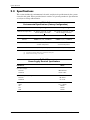
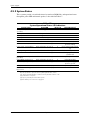
2.4 Specifications. . . . . . . . . . . . . . . . . . . . . . . . . . . . . . . . . . . . . . . . . . . . . . . . . . . . . . . . . . . . . . . 2–10

iv www.hp.com Technical Reference Guide
Contents
3 Processor/Memory Subsystem
3.1 Introduction . . . . . . . . . . . . . . . . . . . . . . . . . . . . . . . . . . . . . . . . . . . . . . . . . . . . . . . . . . . . . . . . . 3–1
3.2 Intel Processor . . . . . . . . . . . . . . . . . . . . . . . . . . . . . . . . . . . . . . . . . . . . . . . . . . . . . . . . . . . . . . . 3–2
3.2.1 Intel Processor Features . . . . . . . . . . . . . . . . . . . . . . . . . . . . . . . . . . . . . . . . . . . . . . . . . . . 3–2
3.2.2 Processor Changing/Upgrading . . . . . . . . . . . . . . . . . . . . . . . . . . . . . . . . . . . . . . . . . . . . . 3–3
3.3 Memory Subsystem . . . . . . . . . . . . . . . . . . . . . . . . . . . . . . . . . . . . . . . . . . . . . . . . . . . . . . . . . . . 3–4
3.3.1 Memory Upgrading . . . . . . . . . . . . . . . . . . . . . . . . . . . . . . . . . . . . . . . . . . . . . . . . . . . . . . 3–5
3.3.2 Memory Mapping and Pre-allocation . . . . . . . . . . . . . . . . . . . . . . . . . . . . . . . . . . . . . . . . 3–5
4 System Support
4.1 Introduction . . . . . . . . . . . . . . . . . . . . . . . . . . . . . . . . . . . . . . . . . . . . . . . . . . . . . . . . . . . . . . . . . 4–1
4.2 PCI Bus Overview . . . . . . . . . . . . . . . . . . . . . . . . . . . . . . . . . . . . . . . . . . . . . . . . . . . . . . . . . . . . 4–1
4.2.1 PCI 2.3 Bus Operation . . . . . . . . . . . . . . . . . . . . . . . . . . . . . . . . . . . . . . . . . . . . . . . . . . . . 4–1
4.2.2 PCI Express Bus Operation . . . . . . . . . . . . . . . . . . . . . . . . . . . . . . . . . . . . . . . . . . . . . . . . 4–2
4.2.3 Option ROM Mapping . . . . . . . . . . . . . . . . . . . . . . . . . . . . . . . . . . . . . . . . . . . . . . . . . . . . 4–3
4.2.4 PCI Interrupts . . . . . . . . . . . . . . . . . . . . . . . . . . . . . . . . . . . . . . . . . . . . . . . . . . . . . . . . . . . 4–3
4.2.5 PCI Power Management Support . . . . . . . . . . . . . . . . . . . . . . . . . . . . . . . . . . . . . . . . . . . . 4–3
4.2.6 PCI Connectors. . . . . . . . . . . . . . . . . . . . . . . . . . . . . . . . . . . . . . . . . . . . . . . . . . . . . . . . . . 4–4
4.3 System Resources . . . . . . . . . . . . . . . . . . . . . . . . . . . . . . . . . . . . . . . . . . . . . . . . . . . . . . . . . . . . 4–6
4.3.1 Interrupts . . . . . . . . . . . . . . . . . . . . . . . . . . . . . . . . . . . . . . . . . . . . . . . . . . . . . . . . . . . . . . 4–6
4.3.2 Direct Memory Access. . . . . . . . . . . . . . . . . . . . . . . . . . . . . . . . . . . . . . . . . . . . . . . . . . . . 4–7
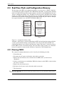
4.4 Real-Time Clock and Configuration Memory. . . . . . . . . . . . . . . . . . . . . . . . . . . . . . . . . . . . . . . 4–8
4.4.1 Clearing CMOS . . . . . . . . . . . . . . . . . . . . . . . . . . . . . . . . . . . . . . . . . . . . . . . . . . . . . . . . . 4–8
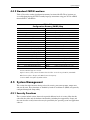
4.4.2 Standard CMOS Locations. . . . . . . . . . . . . . . . . . . . . . . . . . . . . . . . . . . . . . . . . . . . . . . . . 4–9
4.5 System Management . . . . . . . . . . . . . . . . . . . . . . . . . . . . . . . . . . . . . . . . . . . . . . . . . . . . . . . . . . 4–9
4.5.1 Security Functions . . . . . . . . . . . . . . . . . . . . . . . . . . . . . . . . . . . . . . . . . . . . . . . . . . . . . . . 4–9
4.5.2 Power Management . . . . . . . . . . . . . . . . . . . . . . . . . . . . . . . . . . . . . . . . . . . . . . . . . . . . . 4–11
4.5.3 System Status . . . . . . . . . . . . . . . . . . . . . . . . . . . . . . . . . . . . . . . . . . . . . . . . . . . . . . . . . . 4–12
4.5.4 Thermal Sensing and Cooling . . . . . . . . . . . . . . . . . . . . . . . . . . . . . . . . . . . . . . . . . . . . . 4–13
4.6 Register Map and Miscellaneous Functions . . . . . . . . . . . . . . . . . . . . . . . . . . . . . . . . . . . . . . . 4–13
4.6.1 System I/O Map . . . . . . . . . . . . . . . . . . . . . . . . . . . . . . . . . . . . . . . . . . . . . . . . . . . . . . . . 4–13
4.6.2 GPIO Functions . . . . . . . . . . . . . . . . . . . . . . . . . . . . . . . . . . . . . . . . . . . . . . . . . . . . . . . . 4–15
5 Input/Output Interfaces
5.1 Introduction . . . . . . . . . . . . . . . . . . . . . . . . . . . . . . . . . . . . . . . . . . . . . . . . . . . . . . . . . . . . . . . . . 5–1
5.2 SATA/eSATA Interface . . . . . . . . . . . . . . . . . . . . . . . . . . . . . . . . . . . . . . . . . . . . . . . . . . . . . . . 5–2
5.2.1 SATA Inteerface. . . . . . . . . . . . . . . . . . . . . . . . . . . . . . . . . . . . . . . . . . . . . . . . . . . . . . . . . 5–2
5.2.2 eSATA Interface. . . . . . . . . . . . . . . . . . . . . . . . . . . . . . . . . . . . . . . . . . . . . . . . . . . . . . . . . 5–3
5.3 Serial Interface. . . . . . . . . . . . . . . . . . . . . . . . . . . . . . . . . . . . . . . . . . . . . . . . . . . . . . . . . . . . . . . 5–4
5.4 Parallel Interface Support . . . . . . . . . . . . . . . . . . . . . . . . . . . . . . . . . . . . . . . . . . . . . . . . . . . . . . 5–5
5.4.1 Standard Parallel Port Mode. . . . . . . . . . . . . . . . . . . . . . . . . . . . . . . . . . . . . . . . . . . . . . . . 5–5
5.4.2 Enhanced Parallel Port Mode . . . . . . . . . . . . . . . . . . . . . . . . . . . . . . . . . . . . . . . . . . . . . . . 5–5
5.4.3 Extended Capabilities Port Mode. . . . . . . . . . . . . . . . . . . . . . . . . . . . . . . . . . . . . . . . . . . . 5–5
5.4.4 Parallel Interface Connector. . . . . . . . . . . . . . . . . . . . . . . . . . . . . . . . . . . . . . . . . . . . . . . . 5–6
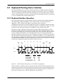
5.5 Keyboard/Pointing Device Interface . . . . . . . . . . . . . . . . . . . . . . . . . . . . . . . . . . . . . . . . . . . . . . 5–7
5.5.1 Keyboard Interface Operation . . . . . . . . . . . . . . . . . . . . . . . . . . . . . . . . . . . . . . . . . . . . . . 5–7
5.5.2 Pointing Device Interface Operation . . . . . . . . . . . . . . . . . . . . . . . . . . . . . . . . . . . . . . . . . 5–8

Technical Reference Guide www.hp.com v
Contents
5.5.3 Keyboard/Pointing Device Interface Connector . . . . . . . . . . . . . . . . . . . . . . . . . . . . . . . . 5–8
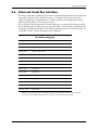
5.6 Universal Serial Bus Interface. . . . . . . . . . . . . . . . . . . . . . . . . . . . . . . . . . . . . . . . . . . . . . . . . . . 5–9
5.6.1 USB Connector. . . . . . . . . . . . . . . . . . . . . . . . . . . . . . . . . . . . . . . . . . . . . . . . . . . . . . . . . . 5–9
5.6.2 USB Cable Data . . . . . . . . . . . . . . . . . . . . . . . . . . . . . . . . . . . . . . . . . . . . . . . . . . . . . . . . 5–10
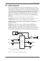
5.7 Audio Subsystem. . . . . . . . . . . . . . . . . . . . . . . . . . . . . . . . . . . . . . . . . . . . . . . . . . . . . . . . . . . . 5–11
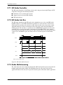
5.7.1 HD Audio Controller . . . . . . . . . . . . . . . . . . . . . . . . . . . . . . . . . . . . . . . . . . . . . . . . . . . . 5–12
5.7.2 HD Audio Link Bus . . . . . . . . . . . . . . . . . . . . . . . . . . . . . . . . . . . . . . . . . . . . . . . . . . . . . 5–12
5.7.3 Audio Multistreaming . . . . . . . . . . . . . . . . . . . . . . . . . . . . . . . . . . . . . . . . . . . . . . . . . . . 5–12
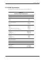
5.7.4 Audio Specifications . . . . . . . . . . . . . . . . . . . . . . . . . . . . . . . . . . . . . . . . . . . . . . . . . . . . 5–13
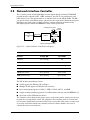
5.8 Network Interface Controller. . . . . . . . . . . . . . . . . . . . . . . . . . . . . . . . . . . . . . . . . . . . . . . . . . . 5–14
5.8.1 Wake-On-LAN Support . . . . . . . . . . . . . . . . . . . . . . . . . . . . . . . . . . . . . . . . . . . . . . . . . 5–15
5.8.2 Alert Standard Format Support . . . . . . . . . . . . . . . . . . . . . . . . . . . . . . . . . . . . . . . . . . . . 5–15
5.8.3 Power Management Support . . . . . . . . . . . . . . . . . . . . . . . . . . . . . . . . . . . . . . . . . . . . . . 5–15
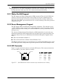
5.8.4 NIC Connector . . . . . . . . . . . . . . . . . . . . . . . . . . . . . . . . . . . . . . . . . . . . . . . . . . . . . . . . 5–15
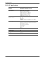
5.8.5 NIC Specifications . . . . . . . . . . . . . . . . . . . . . . . . . . . . . . . . . . . . . . . . . . . . . . . . . . . . . . 5–16
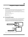
6 Integrated Graphics Subsystem
6.1 Introduction . . . . . . . . . . . . . . . . . . . . . . . . . . . . . . . . . . . . . . . . . . . . . . . . . . . . . . . . . . . . . . . . . 6–1
6.2 Functional Description . . . . . . . . . . . . . . . . . . . . . . . . . . . . . . . . . . . . . . . . . . . . . . . . . . . . . . . . 6–1
6.3 Upgrading . . . . . . . . . . . . . . . . . . . . . . . . . . . . . . . . . . . . . . . . . . . . . . . . . . . . . . . . . . . . . . . . . . 6–5
6.4 Monitor Connectors. . . . . . . . . . . . . . . . . . . . . . . . . . . . . . . . . . . . . . . . . . . . . . . . . . . . . . . . . . . 6–5
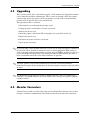
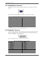
6.5.1 Analog Monitor Connector . . . . . . . . . . . . . . . . . . . . . . . . . . . . . . . . . . . . . . . . . . . . . . . . 6–6
6.5.2 DisplayPort Connector . . . . . . . . . . . . . . . . . . . . . . . . . . . . . . . . . . . . . . . . . . . . . . . . . . . . 6–6
7 Power and Signal Distribution
7.1 Introduction . . . . . . . . . . . . . . . . . . . . . . . . . . . . . . . . . . . . . . . . . . . . . . . . . . . . . . . . . . . . . . . . . 7–1
7.2 Power Distribution. . . . . . . . . . . . . . . . . . . . . . . . . . . . . . . . . . . . . . . . . . . . . . . . . . . . . . . . . . . . 7–1
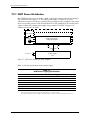
7.2.1 USDT Power Distribution . . . . . . . . . . . . . . . . . . . . . . . . . . . . . . . . . . . . . . . . . . . . . . . . . 7–2
7.2.2 SFF/MT/CMT Power Distribution. . . . . . . . . . . . . . . . . . . . . . . . . . . . . . . . . . . . . . . . . . . 7–2
7.3 Power Control . . . . . . . . . . . . . . . . . . . . . . . . . . . . . . . . . . . . . . . . . . . . . . . . . . . . . . . . . . . . . . . 7–5
7.3.1 Power Button . . . . . . . . . . . . . . . . . . . . . . . . . . . . . . . . . . . . . . . . . . . . . . . . . . . . . . . . . . . 7–5
7.3.2 Wake Up Events. . . . . . . . . . . . . . . . . . . . . . . . . . . . . . . . . . . . . . . . . . . . . . . . . . . . . . . . . 7–7
7.4 Power Management . . . . . . . . . . . . . . . . . . . . . . . . . . . . . . . . . . . . . . . . . . . . . . . . . . . . . . . . . . . 7–7
7.5 Signal Distribution. . . . . . . . . . . . . . . . . . . . . . . . . . . . . . . . . . . . . . . . . . . . . . . . . . . . . . . . . . . . 7–9

vi www.hp.com Technical Reference Guide
Contents
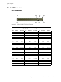
8 SYSTEM BIOS
8.1 Introduction . . . . . . . . . . . . . . . . . . . . . . . . . . . . . . . . . . . . . . . . . . . . . . . . . . . . . . . . . . . . . . . . . 8–1
8.2 ROM Flashing . . . . . . . . . . . . . . . . . . . . . . . . . . . . . . . . . . . . . . . . . . . . . . . . . . . . . . . . . . . . . . . 8–2
8.2.1 Upgrading. . . . . . . . . . . . . . . . . . . . . . . . . . . . . . . . . . . . . . . . . . . . . . . . . . . . . . . . . . . . . . 8–2
8.2.2 Changeable Splash Screen . . . . . . . . . . . . . . . . . . . . . . . . . . . . . . . . . . . . . . . . . . . . . . . . . 8–2
8.3 Boot Functions. . . . . . . . . . . . . . . . . . . . . . . . . . . . . . . . . . . . . . . . . . . . . . . . . . . . . . . . . . . . . . . 8–3
8.3.1 Boot Device Order . . . . . . . . . . . . . . . . . . . . . . . . . . . . . . . . . . . . . . . . . . . . . . . . . . . . . . . 8–3
8.3.2 Network Boot (F12) Support . . . . . . . . . . . . . . . . . . . . . . . . . . . . . . . . . . . . . . . . . . . . . . . 8–3
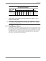
8.3.3 Memory Detection and Configuration . . . . . . . . . . . . . . . . . . . . . . . . . . . . . . . . . . . . . . . . 8–4
8.3.4 Boot Error Codes . . . . . . . . . . . . . . . . . . . . . . . . . . . . . . . . . . . . . . . . . . . . . . . . . . . . . . . . 8–4
8.4 Client Management Functions. . . . . . . . . . . . . . . . . . . . . . . . . . . . . . . . . . . . . . . . . . . . . . . . . . . 8–6
8.4.1 System ID and ROM Type. . . . . . . . . . . . . . . . . . . . . . . . . . . . . . . . . . . . . . . . . . . . . . . . . 8–7
8.4.2 Temperature Status. . . . . . . . . . . . . . . . . . . . . . . . . . . . . . . . . . . . . . . . . . . . . . . . . . . . . . . 8–7
8.5 SMBIOS support . . . . . . . . . . . . . . . . . . . . . . . . . . . . . . . . . . . . . . . . . . . . . . . . . . . . . . . . . . . . . 8–7
8.6 USB Legacy Support. . . . . . . . . . . . . . . . . . . . . . . . . . . . . . . . . . . . . . . . . . . . . . . . . . . . . . . . . . 8–7
8.7 Management Engine Functions . . . . . . . . . . . . . . . . . . . . . . . . . . . . . . . . . . . . . . . . . . . . . . . . . . 8–8
A Error Messages and Codes
A.1 Introduction . . . . . . . . . . . . . . . . . . . . . . . . . . . . . . . . . . . . . . . . . . . . . . . . . . . . . . . . . . . . . . . . A–1
A.2 Beep/Powr LED Codes . . . . . . . . . . . . . . . . . . . . . . . . . . . . . . . . . . . . . . . . . . . . . . . . . . . . . . . A–1
A.3 Power-On Self Test Messages. . . . . . . . . . . . . . . . . . . . . . . . . . . . . . . . . . . . . . . . . . . . . . . . . . A–2
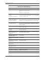
A.4 System Error Messages . . . . . . . . . . . . . . . . . . . . . . . . . . . . . . . . . . . . . . . . . . . . . . . . . . . . . . . A–6
A.5 Memory Error Messages . . . . . . . . . . . . . . . . . . . . . . . . . . . . . . . . . . . . . . . . . . . . . . . . . . . . . . A–7
A.6 Keyboard Error Messages . . . . . . . . . . . . . . . . . . . . . . . . . . . . . . . . . . . . . . . . . . . . . . . . . . . . . A–8
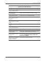
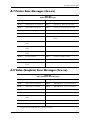
A.7 Printer Error Messages . . . . . . . . . . . . . . . . . . . . . . . . . . . . . . . . . . . . . . . . . . . . . . . . . . . . . . . A–9
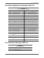
A.8 Video (Graphics) Error Messages . . . . . . . . . . . . . . . . . . . . . . . . . . . . . . . . . . . . . . . . . . . . . . . A–9
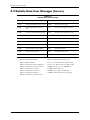
A.9 Diskette Drive Error Messages . . . . . . . . . . . . . . . . . . . . . . . . . . . . . . . . . . . . . . . . . . . . . . . . A–10
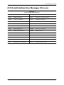
A.10 Serial Inteface Error Messages . . . . . . . . . . . . . . . . . . . . . . . . . . . . . . . . . . . . . . . . . . . . . . . A–11
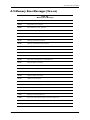
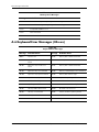
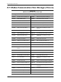
A.11 Modem Communications Error Messages . . . . . . . . . . . . . . . . . . . . . . . . . . . . . . . . . . . . . . A–12
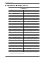
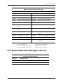
A.12 System Status Error Messages . . . . . . . . . . . . . . . . . . . . . . . . . . . . . . . . . . . . . . . . . . . . . . . A–13
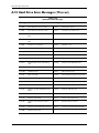
A.13 Hard drive Error Messages . . . . . . . . . . . . . . . . . . . . . . . . . . . . . . . . . . . . . . . . . . . . . . . . . . A–14
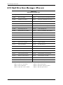
A.14 Hard drive Error Messages . . . . . . . . . . . . . . . . . . . . . . . . . . . . . . . . . . . . . . . . . . . . . . . . . . A–16
A.15 Video (Graphics) Error Messages. . . . . . . . . . . . . . . . . . . . . . . . . . . . . . . . . . . . . . . . . . . . . A–17
A.16 Audio Error Messages. . . . . . . . . . . . . . . . . . . . . . . . . . . . . . . . . . . . . . . . . . . . . . . . . . . . . . A–17
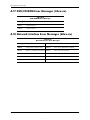
A.17 DVD/CD-ROM Error Messages . . . . . . . . . . . . . . . . . . . . . . . . . . . . . . . . . . . . . . . . . . . . . . A–18
A.18 Netowrk Interface Error Messages . . . . . . . . . . . . . . . . . . . . . . . . . . . . . . . . . . . . . . . . . . . . A–19
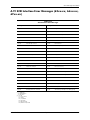
A.19 SCSI Interface Error Messages . . . . . . . . . . . . . . . . . . . . . . . . . . . . . . . . . . . . . . . . . . . . . . . A–19
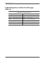
A.20 Pointing Device Interface Error Messages . . . . . . . . . . . . . . . . . . . . . . . . . . . . . . . . . . . . . . A–20
Index

Technical Reference Guide www.hp.com 1-1
1
Introduction
1.1 About this Guide
This guide provides technical information about HP Compaq 8200 Elite Business PC personal
computers that feature the Intel® Q67 Express chipset and support select Intel Celeron®,
Pentium®, Core™ i3, Core i5, and Core i7 processors. This document describes in detail the
system's design and operation for programmers, engineers, technicians, and system
administrators, as well as end-users wanting detailed information.
This guide primarily describes the hardware and firmware elements and primarily deal with the
system board and the power supply assembly. This guide can be used either as an online
document or in hardcopy form.
1.1.1 Online Viewing
Online viewing allows for quick navigating and convenient searching through the document. A
color monitor will also allow the user to view the color shading used to highlight differential
data. A softcopy of the latest edition of this guide is available for downloading in .pdf file format
at the following URL:
www.hp.com
Viewing the file requires a copy of Adobe Acrobat Reader available at no charge from Adobe
Systems, Inc. at the following URL:
www.adobe.com
1.1.2 Hardcopy
A hardcopy of this guide may be obtained by printing from the .pdf file. The document is
designed for printing in an 8 ½ x 11-inch format.
1.2 Additional Information Sources
For more information on components mentioned in this guide refer to the indicated
manufacturers' documentation, which may be available at the following online sources:
■ HP Corporation: www.hp.com
■
Intel Corporation: www.intel.com
■
Serial ATA International Organization (SATA-IO): www.serialATA.org.
■
USB user group: www.usb.org

1-2 www.hp.com Technical Reference Guide
Introduction
1.3 Serial Number
The serial number is located on a sticker placed on the exterior cabinet. The serial number is also
written into firmware and may be read with HP Diagnostics or Insight Manager utilities.
1.4 Notational Conventions
The notational guidelines used in this guide are described in the following subsections.
1.4.1 Special Notices
The usage of warnings, cautions, and notes is described as follows:
WARNING: Text set off in this manner indicates that failure to follow directions could result in bodily
harm or loss of life.
CAUTION: Text set off in this manner indicates that failure to follow directions could result in damage
to equipment or loss of information.
✎
Text set off in this manner provides information that may be helpful.
1.4.2 Values
Differences between bytes and bits are indicated as follows:
MB = megabytes
Mb = megabits

Technical Reference Guide www.hp.com 1-3
Introduction
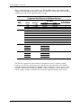
1.5 Common Acronyms and Abbreviations
Table 1-1 lists the acronyms and abbreviations used in this guide.
Table 1-1
Acronyms and Abbreviations
Acronym or
Abbreviation Description
Aampere
AC alternating current
ACPI Advanced Configuration and Power Interface
A/D analog-to-digital
ADC Analog-to-digital converter
ADD or ADD2 Advanced digital display (card)
AHCI SATA Advanced Host controller Interface
AMT Active Management Technology
API application programming interface
APIC Advanced Programmable Interrupt Controller
APM advanced power management
AOL Alert-On-LAN™
ASIC application-specific integrated circuit
ASF Alert Standard Format
AT 1. attention (modem commands) 2. 286-based PC architecture
ATA AT attachment (IDE protocol)
ATAPI ATA w/packet interface extensions
AVI audio-video interleaved
AVGA Advanced VGA
AWG American Wire Gauge (specification)
BAT Basic assurance test
BCD binary-coded decimal
BIOS basic input/output system
bis second/new revision
BNC Bayonet Neill-Concelman (connector type)
bps or b/s bits per second
BSP Bootstrap processor
BTO Built to order
CAS column address strobe
CD compact disk
CD-ROM compact disk read-only memory
CDS compact disk system

1-4 www.hp.com Technical Reference Guide
Introduction
CGA color graphics adapter
Ch Channel, chapter
cm centimeter
CMC cache/memory controller
CMOS complimentary metal-oxide semiconductor (configuration memory)
Cntlr controller
Cntrl control
codec 1. coder/decoder 2. compressor/decompressor
CPQ Compaq
CPU central processing unit
CRIMM Continuity (blank) RIMM
CRT cathode ray tube
CSM 1. Compaq system management 2. Compaq server management
DAC digital-to-analog converter
DC direct current
DCH DOS compatibility hole
DDC Display Data Channel
DDR Double data rate (memory)
DIMM dual inline memory module
DIN Deutche IndustriNorm (connector type)
DIP dual inline package
DMA direct memory access
DMI Direct Media Interface
DP DisplayPort
dpi dots per inch
DRAM dynamic random access memory
DRQ data request
DVI Digital video interface
dword Double word (32 bits)
EDID extended display identification data
EDO extended data out (RAM type)
EEPROM electrically erasable PROM
EIA Electronic Industry Association
EPP enhanced parallel port
Table 1-1 (Continued)
Acronyms and Abbreviations
Acronym or
Abbreviation Description

Technical Reference Guide www.hp.com 1-5
Introduction
EIDE enhanced IDE
eSATA external SATA
ESCD Extended System Configuration Data (format)
EV Environmental Variable (data)
ExCA Exchangeable Card Architecture
FDI Flexible Display Interface
FIFO first in/first out
FL flag (register)
FM frequency modulation
FPM fast page mode (RAM type)
FPU Floating point unit (numeric or math coprocessor)
FPS Frames per second
ft Foot/feet
GB gigabyte
GMCH Graphics/memory controller hub
GND ground
GPIO general purpose I/O
GPOC general purpose open-collector
GART Graphics address re-mapping table
GUI graphic user interface
hhexadecimal
HDD hard disk drive
HW hardware
hex hexadecimal
Hz Hertz (cycles-per-second)
ICH I/O controller hub
IDE integrated drive element
IEEE Institute of Electrical and Electronic Engineers
IF interrupt flag
I/F interface
IGC integrated graphics controller
in inch
INT interrupt
I/O input/output
IOPS Input/output Operations Per Second
Table 1-1 (Continued)
Acronyms and Abbreviations
Acronym or
Abbreviation Description

1-6 www.hp.com Technical Reference Guide
Introduction
IrDA Infrared Data Association
IRQ interrupt request
ISA industry standard architecture
Kb/KB kilobits/kilobytes (x 1024 bits/x 1024 bytes)
Kb/s kilobits per second
kg kilogram
KHz kilohertz
kV kilovolt
lb pound
LAN local area network
LCD liquid crystal display
LED light-emitting diode
LGA land grid array
LPC Low pin count
LSI large scale integration
LSb/LSB least significant bit/least significant byte
LUN logical unit (SCSI)
m Meter
MMX multimedia extensions
MPEG Motion Picture Experts Group
MXM Mobile PCI eXpress Module
ms millisecond
MSb/MSB most significant bit/most significant byte
mux multiplex
MVA motion video acceleration
MVW motion video window
n variable parameter/value
NIC network interface card/controller
NiMH nickel-metal hydride
NMI non-maskable interrupt
NRZI Non-return-to-zero inverted
ns nanosecond
NT nested task flag
NTSC National Television Standards Committee
Table 1-1 (Continued)
Acronyms and Abbreviations
Acronym or
Abbreviation Description

Technical Reference Guide www.hp.com 1-7
Introduction
NVRAM non-volatile random access memory
ODD optical disk drive
OS operating system
PAL 1. programmable array logic 2. phase alternating line
PATA Parallel ATA
PC Personal computer
PCA Printed circuit assembly
PCI peripheral component interconnect
PCI-E PCI Express
PCM pulse code modulation
PCMCIA Personal Computer Memory Card International Association
PCH Platform Controller Hub
PEG PCI express graphics
PFC Power factor correction
PIN personal identification number
PIO Programmed I/O
PN Part number
POST power-on self test
PROM programmable read-only memory
PTR pointer
RAID Redundant array of inexpensive disks (drives)
RAM random access memory
RAS row address strobe
rcvr receiver
RDRAM (Direct) Rambus DRAM
RGB red/green/blue (monitor input)
RH Relative humidity
RMS root mean square
ROM read-only memory
RPM revolutions per minute
RTC real time clock
R/W Read/Write
SATA Serial ATA
SCSI small computer system interface
Table 1-1 (Continued)
Acronyms and Abbreviations
Acronym or
Abbreviation Description

1-8 www.hp.com Technical Reference Guide
Introduction
SDR Singles data rate (memory)
SDRAM Synchronous Dynamic RAM
SDVO Serial digital video output
SEC Single Edge-Connector
SECAM sequential colour avec memoire (sequential color with memory)
SF sign flag
SGRAM Synchronous Graphics RAM
SIMD Single instruction multiple data
SIMM single in-line memory module
SMART Self Monitor Analysis Report Technology
SMI system management interrupt
SMM system management mode
SMRAM system management RAM
SODIMM small outline DIMM
SPD serial presence detect
SPDIF Sony/Philips Digital Interface (IEC-958 specification)
SPN Spare part number
SPP standard parallel port
SRAM static RAM
SSD solid state disk (drive)
SSE Streaming SIMD extensions
STN super twist pneumatic
SVGA super VGA
SW software
TAD telephone answering device
TAFI Temperature-sensing And Fan control Integrated circuit
TCP tape carrier package, transmission control protocol
TF trap flag
TFT thin-film transistor
TIA Telecommunications Information Administration
TPE twisted pair ethernet
TPI track per inch
TPM Trusted Platform Module
TTL transistor-transistor logic
Table 1-1 (Continued)
Acronyms and Abbreviations
Acronym or
Abbreviation Description

Technical Reference Guide www.hp.com 1-9
Introduction
TV television
TX transmit
UART universal asynchronous receiver/transmitter
UDMA Ultra DMA
UDIMM unbuffered/unregistered DIMM
UEFI Unified Extensible Firmware Interface
URL Uniform resource locator
us/s microsecond
USB Universal Serial Bus
UTP unshielded twisted pair
Vvolt
VAC Volts alternating current
VDC Volts direct current
VESA Video Electronic Standards Association
VGA video graphics adapter
VLSI very large scale integration
VRAM Video RAM
Wwatt
WOL Wake-On-LAN
WRAM Windows RAM
ZF zero flag
ZIF zero insertion force (socket)
Table 1-1 (Continued)
Acronyms and Abbreviations
Acronym or
Abbreviation Description

1-10 www.hp.com Technical Reference Guide
Introduction

Technical Reference Guide www.hp.com 2-1
2
System Overview
2.1 Introduction
The HP Compaq 8200 Elite Business PC personal computers (Figure 2-1) deliver an outstanding
combination of manageability, serviceability, and compatibility for enterprise environments.
Based on the the Intel Q67 Express chipset and supporting select Intel Celeron®, Pentium®,
Core™ i3, Core i5, and Core i7 processors, these systems emphasize performance along with
industry compatibility. All models feature a similar architecture incorporating both PCI 2.3 and
PCIe 2.0 buses. All models are easily upgradeable and expandable to keep pace with the needs of
the office enterprise.
Figure 2-1. HP Compaq 8200 Elite Business PCs
This chapter includes the following topics:
■ Features (2.2)
■ System architecture (2.3)
■ Specifications (2.4)
HP 8200 Elite CMT
HP 8200 Elite SFF
HP 8200 Elite MT
HP 8200 Elite USDT

2-2 www.hp.com Technical Reference Guide
System Overview
2.2 Features
The following standard features are included on all models unless otherwise indicated:
■ Intel Celeron, Intel Pentium, or Intel Core i3/i5/i7 processor (LGA1155 socket)
■ Independent dual monitor support:
❏ One VGA connector
❏ One DisplayPort (DP) connector with Multimode support
■ PC3-10600 and PC3-8500 DDR3 memorysupport
CAUTION: These products do not support Ultra Low voltage (1.25V) DIMM/SODIMM. Installation of
ultra low voltage memory can cause damage to the system and/or memory.
■ Hard drive fault prediction
■ Ten externally-accessible USB 2.0-compliant ports (four front, six rear)
■ High definition (HD) audio processor with one headphone output, at least one microphone
input, one line output, and one line input
■ Network interface controller providing 10/100/1000Base T support
■ Plug 'n Play compatible (with ESCD support)
■ PS/2 keyboard
■ PS/2 optical scroll mouse
■ HP UEFI BIOS
■ Management/security features including:
❏ Flash ROM Boot Block
❏ Diskette drive disable, boot disable, write protect
❏ Power-on password
❏ Administrator password
❏ Serial port disable
❏ Smart Cover (hood) Lock (CMT, MT, SFF only)
❏ Smart Cover (hood) Sense
❏ USB port disable
❏ Intel Standard Manageability support
❏ Intel vPro Technology support (with selected processors)
❏ HP Virtual Safe Browser
❏ HP ProtectTools Embedded Security

Technical Reference Guide www.hp.com 2-3
System Overview
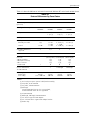
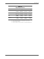
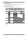
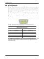
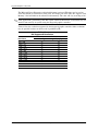
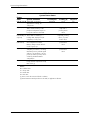
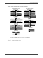
Table 2-1 shows the differences in features between the different PC series based on form factor.
NOTES:
[1] 2nd serial port requires optional cable/bracket assembly.
[2] Low-profile, 25 W maximum.
[3] Low profile, 10-watt maximum
[4] Full-length;
75-watt maximum if PCIe x4 slot is not populated,
35-watt maximum if PCIe x4 slot is populated
[5] 35-watt maximum
[6] Half-height, half-length, 10-watt maximum
[7] 3.5” devices supported with adapters
[8] 2.5” solid state drives supprted with adapter brackets
[9] Slimline bay
Table 2-1
Feature Differences by Form Factor
USDT SFF MT CMT
Thermal Design Power (TPD)
(processor)
65 W 95 W 95 W 95 W
# and type of memory sockets 2 DDR3
SODIMMs
4 DDR3
UDIMMs
4 DDR3
UDIMMs
4 DDR3
UDIMMs
Serial ports 0 1 std.,
1 opt. [1]
1 std.,
1 opt. [1]
1 std.,
1 opt. [1]
Parallel ports 0 optional optional optional
Drive bays:
Externally accessible
Internal
1 [9]
1- 2.50”
1 - 5.25”
1 - 3.50”
1 - 3.50”
2 - 5.25” [7]
1 - 3.50”
2 - 3.50” [8]
3 - 5.25” [7]
3 - 3.50” [8]
# of SATA/eSATA drives
supported:
23/14 5
MXM 3.0 slot? Yes No No No
PCIe slots:
2.0 x16 (graphics)
2.0 x4 (x16 connector)
2.0 x1 connector
1.2 Mini Card 1
(all low profile)
1 [2]
1 [2]
1 [3]
0
(all full height)
1 [4]
1 [5]
1 [6]
0
(all full height)
1 [4]
1 [5]
1 [6]
0
PCI 2.3 32-bit 5-V slot,
25-watt maximum
1 1 full-height 3 full-height
Power Supply Unit:
Module type
Power rating
external
135- or180-watt
internal
240-watt
internal
320-watt
internal
320-watt

2-4 www.hp.com Technical Reference Guide
System Overview
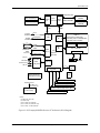
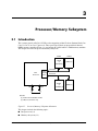
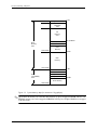
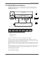
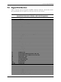
2.3 System Architecture
The systems covered in this guide feature an architecture based on the Intel Celeron, Pentium and
Intel Core i3/i5/17 processors and the Intel Q67 Express Platform Controller Hub (PCH) shown
in Figure 2-2. All systems covered in this guide include the following key components:
■ Intel Pentium processor or Intel Core i3/i5/i7 processor
■ Intel Q67 Express PCH-DO chipset
■ Super I/O (SIO) controller supporting PS/2 keyboard and mouse peripherals
■ ALC261 audio controller supporting line in, line out, microphone in, and headphones out
■ Intel 82579LM GbE network interface controller
■ HP ProtectTools Embedded Security
The Q67 Express PCH provides a major portion of system functionality. Designed to
complement 2nd generation Intel Core processors, the Q67 Express PCH communicates with the
processor through the Flexible Display Interface (FDI) and the Direct Media Interface (DMI).
All systems include a serial ATA (SATA) hard drive in the standard configuration.
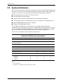
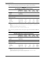
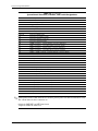
Table 2-2 lists the differences between models by form factor.
Notes:
[1] Low-profile slot.
[2] Operates as SATA 2.0 internally, SATA 1.0 as eSATA
Table 2-2.
Architectural Differences by Form Factor
Function USDT SFF MT CMT
# and type of memory sockets 2 SODIMMs 4 UDIMMs 4 UDIMMs 4 UDIMMs
Maximum amount
of memory supported
8 GB 16 GB 16 GB 16 GB
MXM 3.0 slot 1 0 0 0
PCIe 2.0 x16 graphics slot 0 1 [1] 1 1
PCIe 2.0 x4 slot (x16 connector) 0 1 1 1
PCIe 2.0 x1 slot 0 1 [1] 1 1
PCIe Mini Card 1.2 slot 1 0 0 0
PCI 2.3 slot 0 1 [1] 1 3
SATA interface:
SATA 3.0
SATA 2.0
eSATA [2]
2
0
0
2
1
1
2
1
1
2
2
1
Page is loading ...
Page is loading ...
Page is loading ...
Page is loading ...
Page is loading ...
Page is loading ...
Page is loading ...
Page is loading ...
Page is loading ...
Page is loading ...
Page is loading ...
Page is loading ...
Page is loading ...
Page is loading ...
Page is loading ...
Page is loading ...
Page is loading ...
Page is loading ...
Page is loading ...
Page is loading ...
Page is loading ...
Page is loading ...
Page is loading ...
Page is loading ...
Page is loading ...
Page is loading ...
Page is loading ...
Page is loading ...
Page is loading ...
Page is loading ...
Page is loading ...
Page is loading ...
Page is loading ...
Page is loading ...
Page is loading ...
Page is loading ...
Page is loading ...
Page is loading ...
Page is loading ...
Page is loading ...
Page is loading ...
Page is loading ...
Page is loading ...
Page is loading ...
Page is loading ...
Page is loading ...
Page is loading ...
Page is loading ...
Page is loading ...
Page is loading ...
Page is loading ...
Page is loading ...
Page is loading ...
Page is loading ...
Page is loading ...
Page is loading ...
Page is loading ...
Page is loading ...
Page is loading ...
Page is loading ...
Page is loading ...
Page is loading ...
Page is loading ...
Page is loading ...
Page is loading ...
Page is loading ...
Page is loading ...
Page is loading ...
Page is loading ...
Page is loading ...
Page is loading ...
Page is loading ...
Page is loading ...
Page is loading ...
Page is loading ...
Page is loading ...
Page is loading ...
Page is loading ...
Page is loading ...
Page is loading ...
Page is loading ...
Page is loading ...
Page is loading ...
Page is loading ...
Page is loading ...
Page is loading ...
Page is loading ...
Page is loading ...
Page is loading ...
Page is loading ...
Page is loading ...
Page is loading ...
Page is loading ...
Page is loading ...
-
 1
1
-
 2
2
-
 3
3
-
 4
4
-
 5
5
-
 6
6
-
 7
7
-
 8
8
-
 9
9
-
 10
10
-
 11
11
-
 12
12
-
 13
13
-
 14
14
-
 15
15
-
 16
16
-
 17
17
-
 18
18
-
 19
19
-
 20
20
-
 21
21
-
 22
22
-
 23
23
-
 24
24
-
 25
25
-
 26
26
-
 27
27
-
 28
28
-
 29
29
-
 30
30
-
 31
31
-
 32
32
-
 33
33
-
 34
34
-
 35
35
-
 36
36
-
 37
37
-
 38
38
-
 39
39
-
 40
40
-
 41
41
-
 42
42
-
 43
43
-
 44
44
-
 45
45
-
 46
46
-
 47
47
-
 48
48
-
 49
49
-
 50
50
-
 51
51
-
 52
52
-
 53
53
-
 54
54
-
 55
55
-
 56
56
-
 57
57
-
 58
58
-
 59
59
-
 60
60
-
 61
61
-
 62
62
-
 63
63
-
 64
64
-
 65
65
-
 66
66
-
 67
67
-
 68
68
-
 69
69
-
 70
70
-
 71
71
-
 72
72
-
 73
73
-
 74
74
-
 75
75
-
 76
76
-
 77
77
-
 78
78
-
 79
79
-
 80
80
-
 81
81
-
 82
82
-
 83
83
-
 84
84
-
 85
85
-
 86
86
-
 87
87
-
 88
88
-
 89
89
-
 90
90
-
 91
91
-
 92
92
-
 93
93
-
 94
94
-
 95
95
-
 96
96
-
 97
97
-
 98
98
-
 99
99
-
 100
100
-
 101
101
-
 102
102
-
 103
103
-
 104
104
-
 105
105
-
 106
106
-
 107
107
-
 108
108
-
 109
109
-
 110
110
-
 111
111
-
 112
112
-
 113
113
-
 114
114


Ask a question and I''ll find the answer in the document
Finding information in a document is now easier with AI
Related papers
-
HP Compaq 8000 Elite Ultra-slim PC Technical Reference
-
HP COMPAQ 8100 ELITE SMALL FORM FACTOR PC Technical Reference
-
HP KP721AV User manual
-
HP dc73 Blade Workstation Client Specification
-
HP 8200 Microtower Specification
-
HP 8200 USDT Specification
-
HP 8200 Specification
-
HP 8300 CMT Specification
-
HP Compaq dx7200 Slim Tower PC Technical Reference
-
HP XZ789UT User manual