Page is loading ...

Dell™Latitude™ATGD620ServiceManual
Notes, Notices, and Cautions
Information in this document is subject to change without notice.
©2007DellInc.Allrightsreserved.
Reproduction in any manner whatsoever without the written permission of Dell Inc. is strictly forbidden.
Trademarks used in this text: Dell, the DELL logo, and Latitude are trademarks of Dell Inc.; Microsoft and Windows are registered trademarks of Microsoft Corporation; Bluetooth is a
registered trademark owned by Bluetooth SIG, Inc. and is used by Dell under license.
Other trademarks and trade names may be used in this document to refer to either the entities claiming the marks and names or their products. Dell Inc. disclaims any
proprietary interest in trademarks and trade names other than its own.
Model PP18L
January 2007 Rev. A00
Before You Begin
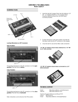
Media Bay Devices
Hard Drive
Hinge Cover
Keyboard
Memory
Display Assembly
Internal Card With Bluetooth®Wireless Technology
Communications Cards
Coin-Cell Battery
Palm Rest
Modem
Processor Thermal-Cooling Assembly
Processor
Speaker
PC Card Reader
System Board
Fan
Base
Flashing the BIOS
NOTE: A NOTE indicates important information that helps you make better use of your computer.
NOTICE: A NOTICE indicates either potential damage to hardware or loss of data and tells you how to avoid the problem.
CAUTION: A CAUTION indicates a potential for property damage, personal injury, or death.

Back to Contents Page
Base
Dell™Latitude™ATGD620ServiceManual
1. Follow the instructions in Before You Begin.
2. Remove the system board (see System Board).
3. Remove the fan (see Fan).
Back to Contents Page
CAUTION: Before working inside your computer, follow the safety instructions in the Product Information Guide.
CAUTION: To prevent static damage to components inside your computer, discharge static electricity from your body before you touch any of
your computer's electronic components. You can do so by touching an unpainted metal surface.
NOTE: If the base has the improved K-Lock, the K-Lock is held down with a screw. Remove and discard the screw when installing this base, as the
screw is not needed.
1
K-Lock assembly
2
base

Back to Contents Page
Before You Begin
Dell™Latitude™ATGD620ServiceManual
Recommended Tools
Turning Off Your Computer
Before Working Inside Your Computer
This document provides procedures for removing and installing the components in your computer. Unless otherwise noted, each procedure assumes the
following:
l You have performed the steps in Turning Off Your Computer and Before Working Inside Your Computer.
l You have read the safety information in the Product Information Guide.
l A component can be replaced by performing the removal procedure in reverse order.
Recommended Tools
The procedures in this document may require the following tools:
l Small flat-blade screwdriver
l Phillips screwdriver
l Small plastic scribe
l 5-mm hex nut driver
l Flash BIOS-update program CD
l Processor extraction tool
Turning Off Your Computer
1. Shut down the operating system:
a. Save and close any open files and exit any open programs
b. Click Start® Shut Down® Shut down.
The computer turns off after the operating system shutdown process finishes.
2. Ensure that the computer and any attached devices are turned off. If your computer and attached devices do not automatically turn off when you shut
down your operating system, press and hold the power button for 4 seconds.
Before Working Inside Your Computer
Use the following safety guidelines to help protect your computer from potential damage and to help ensure your own personal safety.
1. Ensure that the work surface is flat and clean to prevent the computer cover from being scratched.
2. Turn off your computer (see Turning Off Your Computer).
NOTICE: To avoid losing data, save and close any open files and exit any open programs before you turn off your computer.
CAUTION: Before you begin any of the procedures in this section, follow the safety instructions in the Product Information Guide.
CAUTION: Handle components and cards with care. Do not touch the components or contacts on a card. Hold a card by its edges or by its metal
mounting bracket. Hold a component such as a processor by its edges, not by its pins.
NOTICE: Only a certified service technician should perform repairs on your computer. Damage due to servicing that is not authorized by Dell is not
covered by your warranty.
NOTICE: When you disconnect a cable, pull on its connector or on its pull-tab, not on the cable itself. Some cables have a connector with locking tabs; if
you are disconnecting this type of cable, press in on the locking tabs before you disconnect the cable. As you pull connectors apart, keep them evenly
aligned to avoid bending any connector pins. Also, before you connect a cable, ensure that both connectors are correctly oriented and aligned.
NOTICE: To avoid damaging the computer, perform the following steps before you begin working inside the computer.

3. Disconnect any telephone, network, and USB cables from the computer.
4. Disconnect your computer and all attached devices from their electrical outlets.
5. Turn over the computer.
6. Remove the battery:
a. Slide the two battery-bay latch releases on the bottom of the computer toward the sides of the computer until they are engaged.
b. Grasp the battery by the battery tab and slide the battery horizontally toward the front of the computer.
c. Lift to remove the battery from the bay.
7. Press the power button to ground the system board.
8. Remove any PC Card or ExpressCard, if installed, from the PC Card slot.
Back to Contents Page
NOTICE: To disconnect a network cable, first unplug the cable from your computer and then unplug it from the network device.
NOTICE: To avoid damaging the system board, you must remove the main battery before you service the computer.
1
battery
2
battery-bay latch releases (2)
3
battery tab

Back to Contents Page
Flashing the BIOS
Dell™Latitude™ATGD620ServiceManual
Flashing the BIOS From a CD
Flashing the BIOS From the Hard Drive
If a BIOS-update program CD is provided with the new system board, flash the BIOS from the CD. If you do not have a BIOS-update program CD, flash the
BIOS from the hard drive.
Flashing the BIOS From a CD
1. Ensure that the AC adapter is plugged in and that the main battery is installed properly.
2. Insert the BIOS-update program CD, and restart the computer.
Follow the instructions that appear on the screen. The computer continues to boot and updates the new BIOS. When the flash update is complete, the
computer will automatically reboot.
3. Press <F2> during POST to enter the system setup program.
4. Press <Alt> and <F> to reset the computer defaults.
5. Press <Esc>, select Save changes and reboot, and press <Enter> to save configuration changes.
6. Remove the flash BIOS-update program CD from the drive and restart the computer.
Flashing the BIOS From the Hard Drive
1. Ensure that the AC adapter is plugged in, the main battery is properly installed, and a network cable is attached.
2. Turn on the computer.
3. Locate the latest BIOS update file for your computer at support.dell.com.
4. Click Download Now to download the file.
5. If the Export Compliance Disclaimer window appears, click Yes, I Accept this Agreement.
The File Download window appears.
6. Click Save this program to disk and then click OK.
The Save In window appears.
7. Click the down arrow to view the Save In menu, select Desktop, and then click Save.
The file downloads to your desktop.
8. Click Close if the Download Complete window appears.
The file icon appears on your desktop and is titled the same as the downloaded BIOS update file.
9. Double-click the file icon on the desktop and follow the instructions on the screen.
Back to Contents Page
NOTE: If you use a BIOS-update program CD to flash the BIOS, set up the computer to boot from a CD before inserting the CD.

Back to Contents Page
Internal Card With Bluetooth®Wireless Technology
Dell™Latitude™ATGD620ServiceManual
If you ordered an internal card with Bluetooth wireless technology with your computer, it is already installed.
1. Follow the procedures in Before You Begin.
2. Remove the hinge cover (see Hinge Cover).
3. Carefully remove the card cable from its routing guide.
4. While grasping the card cable with one hand, gently press slightly downward (with a plastic scribe) on the tiny, plastic securing tab (shown below) to
release the cable end of the card.
5. Continue to grasp the card cable with one hand while gently prying the card out from underneath the metal tab with the other hand.
CAUTION: Before working inside your computer, follow the safety instructions in your Product Information Guide.
NOTICE: To avoid electrostatic discharge, ground yourself by using a wrist grounding strap or by periodically touching a connector on the back panel of
the computer.
NOTICE: To avoid damaging the system board, you must remove the main battery before you begin working inside the computer (see Before Working
Inside Your Computer).
NOTICE: Be careful when removing the card to avoid damaging the card, card cable, or surrounding components.
1
connector wire
2
plastic scribe
3
plastic securing tab
4
metal securing tab
5
plastic securing tab
1
cable
2
card connector
3
card
4
metal tab
5
plastic scribe


Back to Contents Page
Coin-Cell Battery
Dell™Latitude™ATGD620ServiceManual
1. Follow the procedures in Before You Begin.
2. Remove the hinge cover (see Hinge Cover).
3. Remove the keyboard (see Keyboard).
4. Remove the battery cable connector from the connector on the system board.
5. Being careful not to break the plastic, slightly raise the corner of the plastic arm above the battery.
6. While holding the plastic arm slightly up, grasp the battery and pull it out of the battery compartment.
Back to Contents Page
CAUTION: Before working inside your computer, follow the safety instructions in your Product Information Guide.
NOTICE: To avoid electrostatic discharge, ground yourself by using a wrist grounding strap or by periodically touching a connector on the back panel of
the computer.
NOTICE: To avoid damaging the system board, you must remove the main battery before you begin working inside the computer.
1
battery cable connector
2
coin-cell battery
3
plastic arm

Back to Contents Page
Processor
Dell™Latitude™ATGD620ServiceManual
Removing the Processor
Installing the Processor
Removing the Processor
1. Follow the instructions in Before Working Inside Your Computer.
2. Remove the hinge cover (see Hinge Cover).
3. Remove any installed media bay device (see Media Bay Devices).
4. Remove the keyboard (see Keyboard).
5. Remove the palm rest (see Palm Rest).
6. Remove the processor thermal-cooling assembly (see Processor Thermal-Cooling Assembly).
7. To loosen the ZIF socket, use a small, flat-blade screwdriver and rotate the ZIF-socket cam screw counterclockwise until it comes to the cam stop.
The ZIF-socket cam screw secures the processor to the system board. Take note of the arrow on the ZIF-socket cam screw.
8. Use a processor extraction tool to remove the processor.
CAUTION: Before working inside your computer, follow the safety instructions in the Product Information Guide.
CAUTION: To prevent static damage to components inside your computer, discharge static electricity from your body before you touch any of
your computer's electronic components. You can do so by touching an unpainted metal surface.
NOTICE: To prevent intermittent contact between the ZIF-socket cam screw and the processor when removing or replacing the processor, press to
apply slight pressure to the center of the processor while turning the cam screw.
NOTICE: To avoid damage to the processor, hold the screwdriver so that it is perpendicular to the processor when turning the cam screw.
NOTICE: When removing the processor, pull it straight up. Be careful not to bend the pins on the processor.
1
ZIF-socket cam screw
2
ZIF-socket
3
pin-1 corner of processor

Installing the Processor
1. Align the pin-1 corner of the processor so that it points to the triangle on the system board, and insert the processor into the ZIF socket.
When the processor is correctly seated, all four corners are aligned at the same height. If one or more corners of the processor are higher than the
others, the processor is not seated correctly.
2. Tighten the ZIF socket by turning the cam screw clockwise to secure the processor to the system board.
3. Peel the backing off the thermal cooling pad and adhere the pad to the portion of the thermal-cooling assembly that covers the processor.
4. Replace the processor thermal-cooling assembly (see Processor Thermal-Cooling Assembly).
5. Replace the palm rest (see Palm Rest).
6. Replace the keyboard (see Keyboard).
7. Replace the media bay device (see Media Bay Devices).
8. Replace the hinge cover (see Hinge Cover).
9. Replace the battery.
10. Update the BIOS using a flash BIOS-update program CD. See Flashing the BIOS.
Back to Contents Page
NOTICE: Ensure that the cam lock is in the fully open position before seating the processor. Seating the processor properly in the ZIF socket does not
require force.
NOTICE: A processor that is not properly seated can result in an intermittent connection or permanent damage to the processor and ZIF socket.
NOTICE: To prevent intermittent contact between the ZIF-socket cam screw and the processor when removing or replacing the processor, press to
apply slight pressure to the center of the processor while turning the cam screw.
NOTE: Ensure that you reconnect the coin-cell battery (see Coin-Cell Battery) before you replace the keyboard.

Back to Contents Page
Display Assembly
Dell™Latitude™ATGD620ServiceManual
Removing the Display Assembly
Removing the Display Bezel
Removing the Display Panel
Removing the Display Panel Brackets
Removing the Display Panel Cable
Removing the Display Hinges
Removing the Display Assembly
1. Follow the instructions in Before You Begin.
2. Remove the hinge cover (see Hinge Cover).
3. Remove the keyboard (see Keyboard).
4. Pull straight up on the pull-tab that is attached to the display-feed flex cable to disconnect the cable from the system board.
5. Disconnect the antenna cables from their card(s) (see Communications Cards).
6. Carefully remove the antenna cables and the display cable from their routing guides.
7. Close the display.
8. Turn the computer upside-down with the back of the computer facing you.
CAUTION: Before working inside your computer, follow the safety instructions in the Product Information Guide.
CAUTION: To prevent static damage to components inside your computer, discharge static electricity from your body before you touch any of
your computer's electronic components. You can do so by touching an unpainted metal surface.
1
WWAN card connector
2
WWAN antenna cables
3
WLAN antenna cables
(black and white)
4
WLAN card
5
pull-tab
6
display cable
7
WLAN antenna cables
(white and gray)
8
WLAN antenna cable
(currently unused) (gray)
NOTICE: To avoid damage to your computer, use the illustration above when replacing the display assembly to carefully reroute the cables in the
appropriate cable channels. Route the gray and black antenna cables beneath the white antenna cable, and the black display cable on top of the white
antenna cable.

9. From the bottom of the computer, remove the two M2.5 x 8-mm screws labeled "D."
10. From the back of the computer, remove the two M2.5 x 8-mm screws.
11. Turn the computer right-side up and open the display.
12. Lift the display assembly out of the computer base.
Removing the Display Bezel
1. Follow the instructions in Before You Begin.
2. Remove the display assembly (see Display Assembly).
1
antenna cables (2)
2
display cable pull-tab
CAUTION: Before working inside your computer, follow the safety instructions in the Product Information Guide.
CAUTION: To prevent static damage to components inside your computer, discharge static electricity from your body before you touch any of
your computer's electronic components. You can do so by touching an unpainted metal surface.

3. Use a plastic scribe to pry the six rubber screw covers/display bumpers out of the screw holes on the front of the bezel.
4. Remove the six M2.5 x 5-mm shoulder screws from the front of the bezel.
5. Starting from the inside edges of the bezel, use your fingers to gently pry the bezel upward and outward from the display panel.
Removing the Display Panel
1. Follow the instructions in Before You Begin.
2. Remove the display assembly (see Display Assembly).
3. Remove the display bezel (see Removing the Display Bezel).
4. Remove the three M2 x 3-mm screws from each side of the display panel.
NOTICE: Carefully separate the bezel from the display back cover to avoid damage to the bezel.
1
screw covers/display bumpers (6)
2
M2.5 x 5-mm shoulder screws (6)
3
display bezel
4
display panel
5
display back cover
NOTICE: To avoid damaging the computer when replacing the display bezel, ensure that the bezel edges line up with those on the display back cover,
and snap into place around the entire perimeter of the display back cover.
CAUTION: Before working inside your computer, follow the safety instructions in the Product Information Guide.
CAUTION: To prevent static damage to components inside your computer, discharge static electricity from your body before you touch any of
your computer's electronic components. You can do so by touching an unpainted metal surface.
1
display panel
2
M2 x 3-mm screws (6)
3
display back cover

5. Lift the display panel a few inches from the display back cover.
6. Draw the LED ribbon-cable release tab away from the display panel to release the ribbon cable, and lift the display panel fully from the display back
cover.
Removing the Display Panel Brackets
1. Follow the instructions in Before You Begin.
2. Remove the display assembly (see Display Assembly).
3. Remove the display bezel (see Removing the Display Bezel).
4. Remove the display panel (see Removing the Display Panel).
5. Remove the four M2 x 3-mm screws from each side of the display panel.
Removing the Display Panel Cable
1. Follow the instructions in Before You Begin.
2. Remove the display assembly (see Display Assembly).
3. Remove the display bezel (see Removing the Display Bezel).
4. Remove the display panel (see Removing the Display Panel).
5. Turn over the display panel, placing it on a clean surface.
4
LED ribbon-cable release tab
5
LED ribbon cable
6
bracket tabs (4)
CAUTION: To avoid damage to your display panel, handle the panel by the bracket tabs only.
CAUTION: Before working inside your computer, follow the safety instructions in the Product Information Guide.
CAUTION: To prevent static damage to components inside your computer, discharge static electricity from your body before you touch any of
your computer's electronic components. You can do so by touching an unpainted metal surface.
1
display
panel
2
display panel brackets (2) (left and right of
display panel)
3
M2 x 3-mm screws
(4)
CAUTION: Before working inside your computer, follow the safety instructions in the Product Information Guide.
CAUTION: To prevent static damage to components inside your computer, discharge static electricity from your body before you touch any of
your computer's electronic components. You can do so by touching an unpainted metal surface.
NOTICE: To avoid damage to the computer when replacing the bottom flex cable, gently support the bottom of the inverter board with one finger as
you reseat the bottom flex-cable connector. Do not bend the inverter board.

6. Gently pull the pull-tab on the bottom flex-cable connector to release the cable from the inverter board.
7. Squeeze the flex-cable release levers at either side of the top flex-cable connector, releasing the connector.
Removing the Display Hinges
1. Follow the instructions in Before You Begin.
2. Remove the display assembly (see Display Assembly).
3. Remove the display bezel (see Removing the Display Bezel).
4. Remove the display Panel (see Removing the Display Panel).
5. Remove the M2.5 x 5-mm screw from the right display hinge.
6. Lift the right display hinge off the two alignment pins and out of the display back cover.
7. Repeat step5 and step6 for the left display hinge.
Back to Contents Page
1
top flex-cable
connector
2
flex-cable release levers (2)
3
back of display
panel
4
inverter board
5
pull-tab on bottom flex-cable
connector
CAUTION: Before working inside your computer, follow the safety instructions in the Product Information Guide.
CAUTION: To prevent static damage to components inside your computer, discharge static electricity from your body before you touch any of
your computer's electronic components. You can do so by touching an unpainted metal surface.
1
M2.5 x 5-mm screw
2
display hinges (2)
(left and right)
3
display back cover
4
alignment pin


Back to Contents Page
Fan
Dell™Latitude™ATGD620ServiceManual
1. Follow the instructions in Before You Begin.
2. Remove the system board (see System Board).
3. Remove the M2.5 x 5-mm screw that secures the fan to the base.
4. Lift the fan assembly out of the base.
Back to Contents Page
CAUTION: Before working inside your computer, follow the safety instructions in the Product Information Guide.
CAUTION: To prevent static damage to components inside your computer, discharge static electricity from your body before you touch any of
your computer's electronic components. You can do so by touching an unpainted metal surface.
1
fan assembly
1
M2.5 x 5-mm screw
3
fan power cable

Back to Contents Page
Hard Drive
Dell™Latitude™ATGD620ServiceManual
To replace the hard drive in the hard drive bay:
1. Follow the procedures in Before You Begin.
2. Turn the computer over, and remove the two hard drive screws.
3. Slide the hard drive out of the computer.
4. Remove the new drive from its packaging.
Save the original packaging for storing or shipping the hard drive.
5. Slide the hard drive into the bay until it is fully seated.
6. Replace and tighten the two screws.
7. Use the Operating System CD to install the operating system for your computer (see your User's Guide for information).
8. Use the Drivers and Utilities CD to install the drivers and utilities for your computer (see your User's Guide for information).
Back to Contents Page
CAUTION: If you remove the hard drive from the computer when the drive is hot, do not touch the metal housing of the hard drive.
CAUTION: Before working inside your computer, follow the safety instructions in the Product Information Guide.
NOTICE: To prevent data loss, turn off your computer before removing the hard drive. Do not remove the hard drive while the computer is on, in
standby mode, or in hibernate mode.
NOTICE: Hard drives are extremely fragile; even a slight bump can damage the drive.
NOTE: Dell does not guarantee compatibility or provide support for hard drives from sources other than Dell.
NOTE: You need the Operating System CD to install the Microsoft®Windows®operating system. You also need the Drivers and Utilities CD for your
computer to install the drivers and utilities on the new hard drive.
1
screws (2)
2
hard drive
NOTICE: When the hard drive is not in the computer, store it in protective antistatic packaging. See "Protecting Against Electrostatic Discharge" in the
Product Information Guide.
NOTICE: Use firm and even pressure to slide the drive into place. If you use excessive force, you may damage the connector.

Back to Contents Page
Hinge Cover
Dell™Latitude™ATGD620ServiceManual
1. Follow the procedures in Before You Begin.
2. Turn the computer top-side up, and then open the display all the way (180 degrees) so that the display rests on your work surface.
3. Starting on the right side of the computer, use a plastic scribe (inserted into the indent) to pry up the hinge cover. Lift the cover away from the computer
going from the right toward the left, and lay the cover aside.
Before installing the hinge cover, ensure that all cables are routed correctly. Improper routing of the cables can cause damage to the cables.
4. To replace the hinge cover, insert the left edge of the cover into place.
5. Press from left to right until the cover snaps into place, ensuring that the hinge cover edges line up with those on the palm rest.
Back to Contents Page
CAUTION: Before working inside your computer, follow the safety instructions in the Product Information Guide.
NOTICE: To avoid electrostatic discharge, ground yourself by using a wrist grounding strap or by periodically touching an unpainted metal surface (such
as a connector on the back of the computer).
NOTICE: The hinge cover is fragile and can be damaged if extreme force is used. Be careful when removing the hinge cover.
NOTICE: To avoid damaging the hinge cover, do not lift the cover on both sides simultaneously. Removing the hinge cover in a different way than
described may cause the plastic to break.
1
hinge cover
2
plastic scribe
3
indent

Back to Contents Page
Keyboard
Dell™Latitude™ATGD620ServiceManual
Removing the Keyboard
Replacing the Keyboard
Removing the Keyboard
1. Follow the instructions in Before You Begin.
2. Turn the computer right-side up and open it.
3. Remove the hinge cover (see Hinge Cover).
4. Remove the three screws at the top of the keyboard.
5. Easing the edges of the keyboard out of the small detents on the sides, rotate the keyboard up 90- degrees and lay it on the palm rest to gain access
to the keyboard connector.
6. If the keyboard cable is held in place by a locking arm next to the keyboard connector, carefully spread the retaining bracket away from the connector so
that you can pivot the locking arm upward to release the cable.
7. Pull up on the pull-tab to disconnect the keyboard cable connector from the keyboard connector on the system board.
Replacing the Keyboard
1. Connect the keyboard connector to the system board.
CAUTION: Before working inside your computer, follow the safety instructions in the Product Information Guide.
CAUTION: To prevent static damage to components inside your computer, discharge static electricity from your body before you touch any of
your computer's electronic components. You can do so by touching an unpainted metal surface.
NOTICE: The keycaps on the keyboard are fragile, easily dislodged, and time-consuming to replace. Be careful when removing and handling the
keyboard.
1
screws (3)
2
keyboard tabs (5)
3
palm rest
4
pull-tab
5
keyboard-cable locking arm
6
keyboard cable connector
NOTE: Lift the keyboard carefully in step5 to ensure that you do not pull on the keyboard cable.
NOTICE: To avoid scratching the palm rest when replacing the keyboard, hook the tabs along the front edge of the keyboard into the palm rest, and
then secure the keyboard in place.
/