Page is loading ...

Micro Motion
TM
Micro Motion
®
Model
D, DT, and DL Sensor
Multi Language
Installation Instructions
Quick Reference Guide
P/ N 20000174 Rev. A
March 2003

Micro Motion
TM
1
For online technical support, use the EXPERT
2
™ system at
www.expert2.com. To speak to a customer service
representative, call the support center nearest you:
• In the U.K., phone 0800 - 966 180 (toll-free)
• Outside the U.K., phone +31 (0) 318 495 670
• In the U.S.A., phone 1-800-522-MASS (1-800-522-6277)
• In Canada and Latin America, phone (303) 530-8400
• In Asia, phone (65) 6770-8155
Quick Reference Guide
English
March 2003
Micro Motion
®
Model
D, DT, and DL Sensor
Installation Instructions

2
BEFORE YOU BEGIN
About these instructions
This quick reference guide explains basic installation guidelines for all
Micro Motion
®
Model D (except D600), DL, and DT sensors. For more
information about sensors, refer to the instruction manual that was
shipped with the sensor.
European installations
Micro Motion products comply with all applicable European directives
when properly installed in accordance with the instructions in this quick
reference guide. Refer to the EC declaration of conformity for directives
that apply to a specific product.
The EC declaration of conformity, with all applicable European
directives, and the complete ATEX Installation Drawings and Instructions
are available on the internet at www.micromotion.com/atex or through
your local Micro Motion support center.
INTRODUCTION
The sensor makes up one part of a Coriolis flowmeter. The other part is a
transmitter.
Installation options
Model D, DT, and DL sensors may be connected to the Micro Motion
transmitters listed in Table 1.
©2003, Micro Motion, Inc. All rights reserved. Micro Motion is a registered trademark of Micro Motion, Inc. The
Micro Motion and Emerson logos are trademarks of Emerson Electric Co. All other trademarks are property of their
respective owners.

3
Model D, DT, and DL sensors are available with a 9-wire connection to a
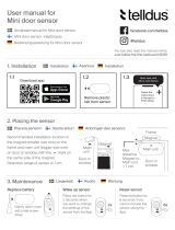
remote transmitter. Refer to Figures 1, 2, 3, and 4 for components of the
sensor. (Note: Figures are not to scale.)
Figure 1. DS025, DH025, DH038, and DS040 sensors
Table 1. Transmitter and sensor compatibility guide
Transmitters
Model D and DL
Sensors Model DT Sensors
Model 1700/2700 (9-wire) X X
Model 3500/3700 (9-wire) X X
RFT9739 (7- or 9-wire) X X
IFT9701 (9-wire) X
RFT9712 (7- or 9-wire) X X
Ground screw
Purge connections
(optional)
Junction box
Sensor housing
Flow direction
arrow
Process connection
Calibration tag
Approvals tag

4
Figure 2. DS065, DS100, DH100, DS150, DH150, DS300, and DH300
sensors
Figure 3. DT065, DT100, and DT150 sensors
Flow direction arrow
Purge connection
(optional)
Calibration tag
Sensor
housing
Junction box
Process connection
Approvals tag
Ground screw
Purge connection
(optional)
Flow direction arrow
Calibration tag
Sensor cable
Process connection
Approvals tag
Ground screw
Lifting handle
Sensor housing

5
Figure 4. DL065, DL100, and DL200 sensors
STEP 1. Determining a location
The sensor may be located anywhere in the process line, as long as the
following conditions are met:
• Before operation, you must be able to stop flow through the sensor.
(During the zeroing procedure, flow must be stopped completely, and
the sensor must be full of process fluid.)
• During operation, the sensor must remain full of process fluid.
• The sensor must be installed in an area that is compatible with the
classification specified on the sensor approvals tag (see Figures 1- 4).
Choose a location for the sensor based on the requirements described in
this section.
Flow direction arrow
Purge connection
(optional)
Sensor housing
Junction box
Purge connection
(optional)
Ground screw
Calibration tag
Approvals tag
Process connection
Process connection

6
Temperature limits
Process fluid temperature limits vary by sensor; refer to Table 2.
.
Process fluid temperature can be further restricted by ambient
temperatures for ATEX approvals. For guidelines, go to
www.micromotion.com/atex.
Maximum wiring distances
The maximum cable length between the sensor and transmitter is located
in Table 3.
Table 2. Temperature specifications
Sensor type °F °C
DS025
–400 to +350 –240 to +177
DS040
–400 to +350 –240 to +177
DS065
–400 to +350 –240 to +177
DS100
–400 to +400 –240 to +204
DS150
–400 to +400 –240 to +204
DS150Z
+32 to +250 0 to +121
DS300
–400 to +400 –240 to +204
DS300Z
+32 to +250 0 to +121
DH025
–400 to +350 –240 to +177
DH038
–400 to +350 –240 to +177
DH100
–400 to +400 –240 to +204
DH150
–400 to +400 –240 to +204
DH300
–400 to +400 –240 to +204
DT065
+32 to +800 0 to +426
DT100
+32 to +800 0 to +426
DT150
+32 to +800 0 to +426
DL065
–400 to +350 –240 to +177
DL100
–400 to +350 –240 to +177
DL200
–400 to +400 –240 to +204
Table 3. Maximum cable lengths
Cable to flowmeter component Maximum length
9-wire to a Model 1700/2700 transmitter 60 feet (20 meters)
9-wire to all other transmitters 1000 feet (300 meters)

7
Hazardous area installations
For installation in an area that requires intrinsic safety, refer to Micro
Motion UL, CSA, SAA, or ATEX documentation, shipped with the
sensor or available from the Micro Motion web site.
For a complete list of hazardous area classifications for Micro Motion
sensors, refer to the Expert
2
™
system at www.expert2.com.
STEP 2. Orienting the sensor
The sensor will function properly in any orientation if the sensor tubes
remain filled with process fluid. Micro Motion recommends installing D,
DT, and DL sensors as shown in Figure 5.
Flow direction arrow
The sensor has a flow direction arrow (see Figures 1-4) to help you
configure the transmitter for flow direction. Process fluid flowing in the
direction opposite to the flow direction arrow may cause unexpected
transmitter output unless the transmitter is configured appropriately. For
instructions on configuring the transmitter’s flow direction parameter,
refer to the transmitter instruction manual.

8
Liq
Figure 5. Recommended orientations for sensors
Orientations for liquids: tubes down, horizontal pipeline
DS025, DH038, DS040 DS065, DS100, DS150,
DS300
DT065, DT100, DT150
Orientations for gases: tubes up, horizontal pipeline, self-draining
DS025, DH038, DS040 DS065, DS100, DS150 DT065, DT100, DT150
Orientations for slurries: flag mount, vertical pipeline
DS025, DH038, DS040 DS065, DS100, DS150,
DS300
DT065, DT100, DT150
Liquids, gases, slurries
Self-draining
Approved by 3A for sanitary applications
DL065, DL100, DL200
Flow
Flow
Flow

9
STEP 3. Mounting the sensor
D and DT sensors
Use your common practices to minimize torque and bending load on
process connections.
Figure 6 illustrates how to mount a D and DT
sensor. If possible, install wiring with the conduit opening pointed down
to reduce the risk of condensation or excessive moisture in the junction
box.
Figure 6. Mounting a D and DT sensor
CAUTION
Using the sensor to support piping can damage the
sensor or cause measurement error.
Do not use the sensor to support pipe.

10
DL sensors
To ensure optimal performance of the DL sensor, follow these guidelines:
• Attach piping to a stable structure in at least one location downstream
and at least one location upstream from the sensor. Put supports as
close as possible to the process connections. Supports should be
attached to the same structure. See Figure 7.
Figure 7. DL sensor installation
• If multiple sensors are installed in series or in parallel, piping to each
sensor must have separate supports. Clamp at least two fixed pipe
supports on piping between sensors installed in series.
• Flexible piping may be installed to minimize piping vibration
transmitted to the sensor. Piping immediately adjacent to the sensor's
process fittings must be rigid.
Approved for 3A sanitary applications
Mounting leg
Pipe clamps and
supports
Mounting leg - bolted to sensor
base plate
Drip leg
Sanitary flow valve
Pipe clamps and
supports
Min. 2 foot (0,6 m) flex cable

11
After process piping has been installed and properly supported, refer to
Figure 8 and follow these guidelines when installing the sensor:
• Install the sensor with user-supplied mounting legs, bolts, and lock
washers (six 1/4 inch-20 UNC for a DL65 or DL100 sensor; two 1/4
inch-20 UNC and four 3/8 inch-16 UNC for a DL200 sensor).
• Use appropriate user-supplied gaskets between process fittings on the
sensor and process piping.
Figure 8. Self-draining DL sensor installations for sanitary
applications
4" (101mm)
minimum
Level
Level
Level
Level
4" (101mm)
minimum
4" (101mm)
minimum
Mounted to floor
Mounted to
ceiling
Mounted to
wall

12
STEP 4. Wiring the sensor to the transmitter
WARNING
Failure to comply with requirements for intrinsic
safety in a hazardous area could result in an
explosion.
• Make sure the hazardous area specified on the sensor
approvals tag is suitable for the environment in which
the sensor is installed. See Figures 1-4.
• For installation in an area that requires intrinsic safety,
refer to Micro Motion UL, CSA, SAA, or ATEX
documentation, shipped with the sensor or available
from the Micro Motion web site.
• For hazardous area installations in Europe, refer to
standard EN 60079-14 if national standards do not
apply.
CAUTION
Failure to seal the sensor junction box housing and
transmitter housing could cause a short circuit,
which would result in measurement error or
flowmeter failure.
• Ensure integrity of gaskets and o-rings.
• Install drip legs in conduit or cable.
• Seal all conduit openings.

13
Model D sensor junction box
Most Model D sensors are shipped with a junction box for wiring. For
Model DT sensors, see Model DT conduit and junction box below. For
Model D and DL sensors:
• If not already installed, install the junction box on the sensor,
following the wiring instructions on the junction box.
• If possible, install wiring with the junction box opening pointed
down, or with a drip leg in the conduit or cable, to reduce the risk of
condensation or excessive moisture in the junction box. See Figure 9.
• Next, follow the guidelines in 9-wire cable wiring to wire the sensor
to the transmitter.
Figure 9. Model D sensor junction box
Model DT conduit and junction box
DT sensors come with a 3-foot (1 meter) pigtail of pre-installed cable and
a 3-foot (1 meter) piece of conduit that needs to be fitted over the pre-
installed cable. Refer to Figure 10.
• Slide the conduit over the pre-installed cable.
• Screw the conduit fitting end into the sensor.
3/4" NPT female
conduit opening
Drip leg in conduit or
cable

14
The other end of the conduit can be connected to a user-supplied junction
box or directly to a transmitter.
• If the conduit is connected to a user-supplied junction box, connect the
wires to the terminals on the junction box. If possible, install wiring
with junction box openings pointed down, or with drip legs in the
conduit, to reduce the risk of condensation or excessive moisture in
the junction box. Next, connect the 9-wire cable from the junction box
to the transmitter by following the instructions in 9-wire cable wiring.
• If the conduit is connected directly to a transmitter, refer to the wiring
instructions in the transmitter Quick Reference Guide.
Figure 10. Model DT sensor wiring
Drip leg
1/2" NPT conduit
fitting
3 ft. (1 m) factory-supplied flex conduit
Liquid tight to meet CE requirements
for European installations
Grounding screw
User-supplied
junction box

15
9-wire cable wiring
Follow the steps below to connect the 9-wire cable between the sensor
and the transmitter.
1. Prepare the cable according to the instructions in Micro Motion’s
9-Wire Flowmeter Cable Preparation and Installation Guide.
2. Insert the stripped ends of the individual wires into the terminal
blocks. No bare wires should remain exposed.
• For D and DL sensors, match the wires color for color. For wiring
at the transmitter, refer to the transmitter Quick Reference Guide.
• For DT sensors, connect the sensor cable wires to the junction
box terminals. Then, connect the 9-wire cable to the junction box
terminals, matching the colors of the wires to the numbers of the
DT sensor terminals, as indicated in Table 4. For wiring at the
transmitter, refer to the transmitter Quick Reference Guide.
3. Tighten the screws to hold the wires in place.
4. Ensure integrity of gaskets, then tightly close and seal the
junction box cover and all housing covers on the transmitter.
Table 4. DT sensor wiring to transmitter
DT sensor terminal number 9-wire cable colors
1Brown
2Red
3 Orange
4 Yellow
5 Green
6Blue
7 Violet
8Gray
9White

16
STEP 5. Grounding the sensor
The sensor can be grounded via the piping if the joints in the pipeline are
ground-bonded. If the sensor is not grounded via the piping, connect a
ground wire to the sensor grounding screw (see Figures 1-4) or the
junction box grounding screw.
If national standards are not in effect, follow these guidelines:
• Use copper wire, 14 AWG (2,5 mm²) or larger wire size for
grounding.
• Keep all ground leads as short as possible, less than 1 ohm impedance.
• Connect ground leads directly to earth, or follow plant standards.
Refer to the transmitter Quick Reference Guide for instructions on
grounding the transmitter.
CAUTION
Improper grounding could cause measurement error.
To reduce the risk of measurement error:
• Ground the flowmeter to earth, or follow ground
network requirements for the facility.
• For installation in an area that requires intrinsic safety,
refer to Micro Motion UL, CSA, SAA, or ATEX
documentation, shipped with the sensor or available
from the Micro Motion web site.
• For hazardous area installations in Europe, refer to
standard EN 60079-14 if national standards do not
apply.

Micro Motion
TM
Micro Motion Europe
Emerson Process Management
Wiltonstraat 30
3905 KW Veenendaal
The Netherlands
T +31 (0) 318 495 670
F +31 (0) 318 495 689
Micro Motion Inc. USA
Worldwide Headquarters
7070 Winchester Circle
Boulder, Colorado 80301
T (303) 530-8400
(800) 522-6277
F (303) 530-8459
Micro Motion Japan
Emerson Process Management
Shinagawa NF Bldg. 5F
1-2-5, Higashi Shinagawa
Shinagawa-ku
Tokyo 140-0002 Japan
T (81) 3 5769-6803
F (81) 3 5769-6843
Micro Motion Asia
Emerson Process Management
1 Pandan Crescent
Singapore 128461
Republic of Singapore
T (65) 6777-8211
F (65) 6770-8003
18
Visit us on the Internet at www.micromotion.com
Micro Motion United Kingdom
Emerson Process Management Limited
Horsfield Way
Bredbury Industrial Estate
Stockport SK6 2SU U.K.
T 0800 966 180
F 0800 966 181
www.emersonprocess.co.uk

Micro Motion
TM
Micro Motion Europe
Emerson Process Management
Wiltonstraat 30
3905 KW Veenendaal
The Netherlands
T +31 (0) 318 495 670
F +31 (0) 318 495 689
Micro Motion Inc. USA
Worldwide Headquarters
7070 Winchester Circle
Boulder, Colorado 80301
T (303) 530-8400
(800) 522-6277
F (303) 530-8459
Micro Motion Japan
Emerson Process Management
Shinagawa NF Bldg. 5F
1-2-5, Higashi Shinagawa
Shinagawa-ku
Tokyo 140-0002 Japan
T (81) 3 5769-6803
F (81) 3 5769-6843
Micro Motion Asia
Emerson Process Management
1 Pandan Crescent
Singapore 128461
Republic of Singapore
T (65) 6777-8211
F (65) 6770-8003
36
Consultez l’actualité Micro Motion sur Internet : www.micromotion.com
Micro Motion France
Emerson Process Management S.A.S.
14, rue Edison - BP 21
69671 Bron Cedex
France
T +33 (0) 4 72 15 98 00
F +33 (0) 4 72 15 98 99
www.emersonprocess.fr
Micro Motion Suisse
Emerson Process Management AG
Blegistraße 21
CH-6341 Baar-Walterswil
Suisse
T +41 (0) 41 768 6111
F +41 (0) 41 768 6300
www.emersonprocess.ch
Micro Motion Belgique
Emerson Process Management nv/sa
De Kleetlaan
1831 Diegem
Belgique
T +32 (0) 2 716 77 11
F +32 (0) 2 725 83 00
www.emersonprocess.be

Micro Motion
TM
Micro Motion Europe
Emerson Process Management
Wiltonstraat 30
3905 KW Veenendaal
The Netherlands
T +31 (0) 318 495 670
F +31 (0) 318 495 689
Micro Motion Inc. USA
Worldwide Headquarters
7070 Winchester Circle
Boulder, Colorado 80301
T (303) 530-8400
(800) 522-6277
F (303) 530-8459
Micro Motion Japan
Emerson Process Management
Shinagawa NF Bldg. 5F
1-2-5, Higashi Shinagawa
Shinagawa-ku
Tokyo 140-0002 Japan
T (81) 3 5769-6803
F (81) 3 5769-6843
54
Besuchen Sie uns im Internet: www.micromotion.com
Micro Motion Deutschland
Emerson Process Management
GmbH & Co. OHG
Argelsrieder Feld 3
D-82234 Weßling
T +49 (0) 8153 939-0
F +49 (0) 8153 939-172
www.emersonprocess.de
Micro Motion Schweiz
Emerson Process Management
AG
Blegistraße 21
6341 Baar-Walterswil
T +41 (0) 41 768 6111
F +41 (0) 41 768 6300
www.emersonprocess.ch
Micro Motion Österreich
Emerson Process Management AG
Industriezentrum NÖ Süd
Straße 2a, Obj. 29
2351 Wr. Neudorf
T +43 (0) 2236-607
F +43 (0) 2236-607 44
www.emersonprocess.at
/