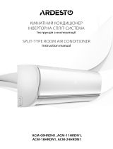
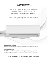
S36MY2E5A

Panasonic S36MY2E5A, S15MK2E5A, S15MY2E5A, S22MK2E5A, S22MY2E5A, S28MK2E5A, S28MY2E5A, S36MK2E5A, S45MY2E5A, S56MY2E5A Operating instructions

  • Hello! I am an AI chatbot trained to assist you with the Panasonic S36MY2E5A Operating instructions. I’ve already reviewed the document and can help you find the information you need or explain it in simple terms. Just ask your questions, and providing more details will help me assist you more effectively!
Operating Instructions
Air Conditioner
Model No.
Indoor Units
4-Way Cassette
60x60 (Y2 type)
S-15MY2E5A
S-22MY2E5A
S-28MY2E5A
S-36MY2E5A
S-45MY2E5A
S-56MY2E5A
Outdoor Units
mini
(LE1 type)
U-4LE1E5
U-5LE1E5
U-6LE1E5
U-4LE1E8
U-5LE1E8
U-6LE1E8
2WAY
(ME1 type)
U-8ME1E81
U-10ME1E81
U-12ME1E81
U-14ME1E81
U-16ME1E81
U-18ME1E81
U-20ME1E81
3WAY
(MF2 type)
U-8MF2E8
U-10MF2E8
U-12MF2E8
U-14MF2E8
U-16MF2E8
Indoor Units
Wall Mounted
(K2 type)
S-15MK2E5A
S-22MK2E5A
S-28MK2E5A
S-36MK2E5A
ENGLISH
FRANÇAIS
ESPAÑOL
DEUTSCH
ITALIANO
NEDERLANDS
PORTUGUÊS
EΛΛΗΝΙΚΆ
БЪЛГАРСКИ
РУССКИЙ
УКРАЇНСЬКА
2 ~ 15
16 ~ 29
30 ~ 43
44 ~ 57
58 ~ 71
72 ~ 85
86 ~ 99
100 ~ 113
114 ~ 127
128 ~ 141
142 ~ 156
Before operating the unit, read these operating instructions thoroughly and keep them for future reference.
B.INDONESIA 158 ~ 171
Avant d’utiliser l’appareil, lisez ce mode d’emploi dans son intégralité et conservez-le pour toute référence ultérieure.
Bevor Sie das Gerät in Betrieb nehmen, lesen Sie bitte diese Bedienungsanleitung aufmerksam
durch und bewahren Sie sie für die künftige Verwendung auf.
Prima di utilizzare l’unità, leggere a fondo queste istruzioni per l’uso e conservarle come riferimento futuro.
Преди да започнете експлоатация на този уред, прочетете внимателно тези инструкции и ги
запазете, за да можете да правите справки с тях и в бъдеще.
Lees deze gebruiksinstructies goed door voor u het apparaat gebruikt en bewaar ze voor toekomstig gebruik.
Antes de utilizar o aparelho, leia completamente este manual de instruções e guarde-o para futuras referências.
Перед использованием этого устройства внимательно прочитайте настоящую инструкцию по
эксплуатации и сохраните ее для дальнейших справок.
Уважно прочитайте цю інструкцію з експлуатації перед тим, як увімкнути пристрій, та
збережіть її на майбутнє.
Πριν θέσετε τη μονάδα σε λειτουργία, διαβάστε πολύ καλά αυτές τις οδηγίες χρήσης και
διατηρήστε τις για μελλοντική αναφορά.
Antes de operar la unidad, lea atentamente estas instrucciones de funcionamiento y guárdelas para futuras consultas.
F569612
Sebelum mengoperasikan unit, baca petunjuk pengoperasian ini secara menyeluruh dan simpan untuk referensi
mendatang.
Panasonic Corporation
1006 Kadoma, Kadoma City, Osaka, Japan
* Shows K2 type (Wall Mounted)
2
CONTENTS
Page
PRODUCT INFORMATION...........................................................................................................2
SAFETY PRECAUTIONS..............................................................................................................2
INSTALLATION LOCATION...........................................................................................................2
ELECTRICAL REQUIREMENTS ..................................................................................................3
SAFETY INSTRUCTIONS.............................................................................................................3
INFORMATION..............................................................................................................................6
OPERATION..................................................................................................................................7
ADJUSTING AIRFLOW DIRECTION............................................................................................9
ADJUSTING AIRFLOW DIRECTION FOR MULTIPLE INDOOR UNITS USING SINGLE
REMOTE CONTROLLER (WIRED) ............................................................................................11
SPECIAL REMARKS ..................................................................................................................12
CARE AND CLEANING ..............................................................................................................12
TROUBLESHOOTING ................................................................................................................14
CHECK BEFORE REQUIRING SERVICES................................................................................15
TIPS FOR ENERGY SAVING .....................................................................................................15
SPECIFICATIONS.....................................................................................................................172
PRODUCT INFORMATION
If you have problems or questions concerning your Air Conditioner, you will need the following
information. Model and serial numbers are on the nameplate on the bottom of the cabinet.
Model No. _________________________________ Serial No. _______________________
Date of purchase ______________________________________________________________
Dealer’s address ______________________________________________________________
Phone number________________________________________________________________
SAFETY PRECAUTIONS
The following symbols used in this manual, alert you to potentially dangerous conditions to users, service personnel or
the appliance:
INSTALLATION LOCATION
We recommend that this air conditioner be installed properly by qualified installation technicians in accordance with
the Installation Instructions provided with the unit.
Before installation, check that the voltage of the electric supply in your home or office is the same as the voltage shown on the
nameplate.
This symbol refers to a hazard or unsafe practice which can result in severe personal
injury or death.
This symbol refers to a hazard or unsafe practice which can result in personal injury or
product or property damage.
Do not install this air conditioner where
there are fumes or flammable gases, or
in an extremely humid space such as a
greenhouse.
Do not install the air conditioner where
excessively high heat-generating objects
are placed.
Avoid: To protect the air conditioner from heavy corrosion, avoid installing the outdoor unit where salty sea water can splash
directly onto it or in sulphurous air near a spa.
01_F569612_EN.fm Page 2 Thursday, September 25, 2014 8:57 AM
3
ELECTRICAL REQUIREMENTS
1. All wiring must conform to the local electrical codes. Consult your dealer or a qualified electrician for details.
2. Each unit must be properly grounded with a ground (or earth) wire or through the supply wiring.
3. Wiring must be done by a qualified electrician.
SAFETY INSTRUCTIONS
Read these Operating Instructions carefully before using this air conditioner. If you still have any difficulties or problems,
consult your dealer for help.
This air conditioner is designed to give you comfortable room conditions. Use this only for its intended purpose as described in
these Operating Instructions.
To warm up the system, the
power mains must be turned
on at least five (5) hours before
operation. Leave the power
mains ON unless you will not
be using this appliance for an
extended period.
Power mains
ON
Disconnect the mains plug from the supply socket and main circuit breaker when not in use for an extended period
of time. When turning off some of the outdoor or indoor units, the entire system becomes inoperative.
NOTE
Confirm to authorized dealer
or specialist on usage of
specified refrigerant type.
Using of refrigerant other than
the specified type may cause
product damage, burst and
injury etc.
Never touch the unit with wet
hands.
Never use or store gasoline or
other flammable vapor or
liquid near the air conditioner
— it is very dangerous.
Do not use this appliance in a
potentially explosive
atmosphere.
This air conditioner has no
ventilator for intaking fresh air
from outdoors. You must open
doors or windows frequently
when you use gas or oil
heating appliances in the
same room, which consume a
lot of oxygen from the air.
Otherwise there is a risk of
suffocation in an extreme
case.
Provide a power outlet to be
used exclusively for each unit,
and a power supply
disconnect, circuit breaker and
earth leakage breaker for
overcurrent protection should
be provided in the exclusive
line.
01_F569612_EN.fm Page 3 Thursday, September 25, 2014 8:57 AM
4
Provide a power outlet
exclusively for each unit, and
full disconnection means
having a contact separation in
all poles must be incorporated
in the fixed wiring in
accordance with the wiring
rules.
To prevent possible
hazards from insulation
failure, the unit must be
grounded.
Do not clean inside the indoor
and outdoor units by users.
Engage authorized dealer or
specialist for cleaning.
In case of malfunction of this
appliance, do not repair by
yourself. Contact to the sales
dealer or service dealer for a
repair.
Refrigerant gas leakage may
cause fire.
For safety, be sure to turn
the air conditioner off and
also to disconnect the power
before cleaning or servicing.
Pull off the power plug from a
receptacle, or switch off the
breaker, or switch off the
power disconnecting mean to
isolate the air conditioner from
the main power supply in case
of emergency.
Do not insert your fingers
or other objects into the air
conditioner indoor or outdoor
unit, rotating parts may cause
injury.
Do not use modified
cord, joint cord,
extension cord or unspecified
cord to prevent overheating
and fire.
Stop using the product when
any abnormality/failure occurs
and disconnect the power
plug or turn off the power
switch and breaker.
(Risk of smoke/fire/electric
shock)
Examples of abnormality/
failure
The ELCB trips frequently.
Burning smell is observed.
Abnormal noise or vibration
of the unit is observed.
Water leaks from the indoor
unit.
Power cord or plug
becomes abnormally hot.
Fan speed cannot be
controlled.
The unit stops running
immediately even if it is
switched on for operation.
The fan does not stop even
if the operation is stopped.
Contact immediately your
local dealer for maintenance/
repair.
01_F569612_EN.fm Page 4 Thursday, September 25, 2014 8:57 AM
5
This appliance is intended to
be used by expert or trained
users in shops, in light industry
and on farms, or for
commercial use by lay persons.
Do not turn the air conditioner
on and off from the power
mains switch. Use the ON/
OFF operation button.
Do not stick anything into
the air outlet of the
outdoor unit. This is
dangerous because the fan is
rotating at high speed.
Do not touch the air inlet
or the sharp aluminum fins
of the outdoor unit. You may
get injured.
Keep the fire alarm and the air
outlet at least 1.5m away from
the unit.
This appliance can be used by
children aged from 8 years and
above and persons with reduced
physical, sensory or mental
capabilities or lack of experience
and knowledge if they have
been given supervision or
instruction concerning use of the
appliance in a safe way and
understand the hazards
involved.
Do not cool or heat the room
too much if babies or invalids
are present.
Do not stick any
object into the FAN
CASE.
You may be injured and the
unit may be damaged.
Do not sit or step on the
unit. You may fall down
accidentally.
The compressor may occasionally stop during thunderstorms.
This is not a mechanical failure. The unit automatically recovers after a few minutes.
The English text is the original instructions. Other languages are translation of the original instructions.
Stop using the product when any abnormality/failure occurs and disconnect
the power plug.
(Risk of smoke/fire/electric shock)
Examples of
abnormality/
failure
- The product sometimes does not start when turned on.
- The power is sometimes disconnected when the cord is moved.
- Burnt odor or abnormal noise is detected during operation.
- The body is deformed or abnormally hot.
Contact immediately your local dealer for maintenance/repair.
IMPORTANT INFORMATION REGARDING THE REFRIGERANT USED
This product contains fluorinated greenhouse gases covered by the Kyoto Protocol. Do not vent gases into the atmosphere.
Refrigerant type: R410A
GWP
(1)
value: 1975
(1)
GWP = global warming potential
Periodical inspections for refrigerant leaks may be required depending on European or local legislation.
Please contact your local dealer for more information.
NOTICE
01_F569612_EN.fm Page 5 Thursday, September 25, 2014 8:57 AM
6
INFORMATION
Operation Condition
Use this air conditioner under the following temperature range.
*DBT: Dry bulb temperature
*WBT: Wet bulb temperature
Outdoor Unit Indoor Outdoor
mini (LE1 type)
Cooling mode 14°C ~ 25°C (*WBT) -10°C ~ 46°C (*DBT)
Heating mode 16°C ~ 30°C (*DBT)
-20°C ~ 18°C (*WBT)
-20°C ~ 24°C (*DBT)
2WAY (ME1 type)
Cooling mode 14°C ~ 25°C (*WBT) -10°C ~ 43°C (*DBT)
Heating mode 16°C ~ 30°C (*DBT) -25°C ~ 15°C (*DBT)
3WAY (MF2 type)
Cooling mode 14°C ~ 25°C (*WBT) -10°C ~ 46°C (*DBT)
Heating mode 15°C ~ 30°C (*DBT) -20°C ~ 18°C (*WBT)
Cooling & heating mode -10°C ~ 24°C (*DBT)
Information for Users on Collection and Disposal of Old Equipment and Used Batteries
These symbols on the products, packaging, and/or accompanying documents mean that used electrical and
electronic products and batteries should not be mixed with general household waste.
For proper treatment, recovery and recycling of old products and used batteries, please take them to
applicable collection points, in accordance with your national legislation and the Directives 2002/96/EC and
2006/66/EC.
By disposing of these products and batteries correctly, you will help to save valuable resources and prevent
any potential negative effects on human health and the environment which could otherwise arise from
inappropriate waste handling.
For more information about collection and recycling of old products and batteries, please contact your local
municipality, your waste disposal service or the point of sale where you purchased the items.
Penalties may be applicable for incorrect disposal of this waste, in accordance with national legislation.
For business users in the European Union
If you wish to discard electrical and electronic equipment, please contact your dealer or supplier for further
information.
[Information on Disposal in other Countries outside the European Union]
These symbols are only valid in the European Union. If you wish to discard these items, please contact your
local authorities or dealer and ask for the correct method of disposal.
Note for the battery symbol (bottom two symbol examples):
This symbol might be used in combination with a chemical symbol. In this case it complies with the requirement
set by the Directive for the chemical involved.
Pb
01_F569612_EN.fm Page 6 Thursday, September 25, 2014 8:57 AM
7
OPERATION
Names of Parts
INDOOR UNIT
Wireless Remote Controller (Optional parts)
High-Spec Wired Remote Controller (Optional parts)
Refer to the Operating Instructions
attached to the optional Wireless
Remote Controller.
Refer to the Operating Instructions
attached to the optional High-Spec
Wired Remote Controller.
O
P
E
N
C
L
O
S
E
C
L
O
S
E
O
P
E
N
Intake grille
Control Panel
Airflow direction
louver
Air is discharged
evenly
Receiver
Emergency button
Front panel
Air filters
Receiver
Emergency button
Do not adjust
by hand.
• Manually
adjustable.
Vertical airflow
direction louver
Horizontal airflow
direction louver
Y2 type (4-WAY CASSETTE 60×60)
K2 type (WALL MOUNTED)
NOTE
(Wireless type: available
for all indoor units)
NOTE
(Wired type:
available for all
indoor units)
01_F569612_EN.fm Page 7 Thursday, September 25, 2014 8:57 AM
8
Timer Remote Controller (Optional parts)
For details, refer to the Operating Instructions attached to the optional Timer
Remote Controller.
NOTE
(Wired type: available for all indoor units)
1
2
5
3
4
Names and Operations
ex.) Timer Remote Controller
Group Control
5. Temperature setting buttons
Changing the temperature setting.
Push the Temperature Setting buttons to change the desired temperature setting.
Operation lamp
Operation lamp
The lamp is turned on when an air
conditioner is in operation.
This lamp blinks when an error occurs or
a protective device is activated.
Group control function is suitable for operating
the multiple air conditioners in a large single room.
Up to 8 units can be connected.
Remote controller
Signal line
Outdoor unit
Operation of all indoor units in the same mode
except for airflow direction.
Use the indoor unit's temperature sensor.
3.
(Fan speed) button
Changing the fan speed.
4.
(Swing/Air direction) button
Push the Swing/Airflow direction button to set the auto swing or air direction to a specific
angle. (For details, see “Adjusting Airflow Direction” section.)
1.
(Start/Stop) button
Pushing this button starts, and pushing
again stops the unit.
Operation lamp :
When started lights up
When stopped goes out
2.
(Mode select) button
Pushing this button to select an operation mode.
HEAT
DRY
COOL
FAN
AUTO COOL-HEAT
... Auto cooling-heating mode detects
the difference between the preset
temperature on the controller and
the actual room temperature.
Then it automatically selects heating
or cooling mode.
(The automatic heating and cooling
control for 2WAY and mini VRF system
can be performed when all indoor units
in the same refrigerant circuit are
controlled in a group control.)
AUTO
STRONG
MEDIUM
WEAK
NOTE :
When Mode select button is set to FAN,
AUTO mode cannot be selected.
01_F569612_EN.fm Page 8 Thursday, September 25, 2014 8:57 AM
9
ADJUSTING AIRFLOW DIRECTION
The functions differ depending on the indoor unit used. The airflow direction cannot be set
using the remote controller for any unit which is not listed below.
Y2 type, K2 type:
Never use your hands to move the flap (vertical airflow flap) that is controlled using the
remote controller.
When the air conditioner is turned off, the flap automatically moves toward the direction of
closing.
The flap (vertical airflow flap) moves to the upward position when performing the standby
operation for heating. The swing operation is made after the standby operation for heating is
released, but swing is indicated on the remote controller even during the standby operation
for heating.
Setting the airflow
direction
The airflow direction changes each time the FLAP button is pressed during operation.
To activate the swing
operation
Press the FLAP button to set the flap (vertical airflow flap) to the downward position, and then
press the FLAP button again. This displays , and the airflow automatically swings up and
down.
To stop the swing
operation
Press the FLAP button again during the flap swing operation to stop the flap at the desired
position. Then, the airflow can be set from the top position by pressing the FLAP button again.
Indicator when swing operation is stopped
During cooling or drying operation, the flap will not stop at the downward position. Even if the
flap is stopped at the downward position during the swing operation, it will not stop until it
moves to the third position from the top.
Heating Cooling and drying Fan operation All operations
Set the flap (vertical airflow flap) to the downward
position. If the flap is set to the upward position,
the warm air may not reach the floor.
The flap (vertical airflow flap) can
be set to one of three positions.
Initial setting
Initial setting
Initial setting
Continuous
operation
Fan and heating Cooling and drying
01_F569612_EN.fm Page 9 Thursday, September 25, 2014 8:57 AM
10
ADJUSTING AIRFLOW DIRECTION (CONTINUED)
4-way cassette (Y2)
Y2 type air conditioner is equipped with auto flaps.
You can set the airflow direction to a specific angle or to the sweep mode using the remote
controller.
Do not move the flap with your hands.
Wall mounted type (K2)
Vertical directions (automatic)
Confirm that the remote controller has been turned on. Press the FLAP button to start the flap
moving up and down. If you want to stop the flap movement and to direct the air in the desired
direction, press the FLAP button again. In the cool mode, do not direct the flap down and move
out of the cooling zone “A”, otherwise, condensation may drip on to the floor. Zone ‘‘A’’ is the
recommended flap position for cooling.
When operating continuously in the fixed airflow direction setting for about an hour, the airflow
direction is automatically controlled and the flap position is changed. The airflow direction may
be different from the display on the remote controller.
Do not move the flap with your hands.
Horizontal directions (manual)
The horizontal airflow direction can be adjusted manually by moving the vertical vanes to the
left or right.
Indoor unit
Zone ‘‘B’’ for
heating
Zone
‘‘A’’ for
cooling
01_F569612_EN.fm Page 10 Thursday, September 25, 2014 8:57 AM
11
ADJUSTING AIRFLOW DIRECTION FOR MULTIPLE
INDOOR UNITS USING SINGLE REMOTE
CONTROLLER (WIRED)
If multiple indoor units are connected to a remote controller, the airflow direction can be set
for each indoor unit by selecting the indoor units (see the operation below).
Auto Flap ( ) button
To set the airflow for individual units, press the UNIT button. Display shows the indoor unit
number under group control. Set the airflow direction for the indoor unit that is shown on the
display.
Each time UNIT is pressed, the indicator changes in the order shown below.
When nothing is displayed, you can make the setting for all indoor units in one operation.
The unit number is displayed as Outdoor Unit Number–Indoor Unit Number. It varies
depending on the number of units under group control.
One outdoor unit and eight indoor units Two outdoor units and four indoor units
No display
Unit No.
1–1
Unit No.
1–2
Unit No.
1–3
Unit No.
1–8
No
display
Unit
No.
1–1
Unit
No.
1–2
Unit
No.
1–3
Unit
No.
2–4
Unit
No.
1–4
Unit
No.
2–1
01_F569612_EN.fm Page 11 Thursday, September 25, 2014 8:57 AM
12
SPECIAL REMARKS
CARE AND CLEANING
How it works Once the room temperature reaches the level that was set, the unit repeats the cycle of
turning on and off automatically.
In order to prevent the humidity in the room from rising again, the indoor fan also turns off
when the unit stops operating.
The fan speed is set to ‘‘LO.’ automatically, and cannot be adjusted.
‘DRY’ operation is not possible if the outdoor temperature is 15 °C or less.
Heating performance Because this appliance heats a room by utilizing the heat of the outside air (heat pump
system), the heating efficiency will fall off when the outdoor temperature is very low. If
sufficient heat cannot be obtained with this heat pump, use another heating appliance in
conjunction with this unit.
Defrosting When the outdoor temperature is low, frost or ice may form on the outdoor heat exchanger
coil, reducing the heating performance. When this happens, a microcomputer-controlled
defrosting system operates. At the same time, the fan on the indoor unit stops (or runs at
very low speed in some cases) and the ‘‘STANDBY’’ indicator appears on the display until
defrosting is completed. Heating operation then restarts after several minutes. (This interval
will vary slightly depending upon the outdoor temperature and the way in which frost forms.)
(standby) on the
display
For several minutes after the start of heating operation, the indoor fan will not start running
(or it will run at very low speed in some cases) until the indoor heat exchanger coil has
warmed up sufficiently. This is because a cold draft prevention system is operating. During
this period, the ‘‘ ’ (standby) indicator remains displayed.
‘‘ ’ (standby) remains displayed during defrosting or when the compressor has been
turned off (or when the unit is running at very low speed) by the thermostat when the
system is in the heating mode.
Upon completion of defrosting and when the compressor is turned on again, ‘ ’’
(standby) will turn off automatically as heating operation resumes.
Should the power fail while the unit is running
If the power supply for this unit is temporarily cut off, the unit will automatically resume
operation (once the power is restored) using the same settings before the power was cut off.
1. For safety, be sure to turn the air conditioner off and also to disconnect the power
before cleaning.
2. Do not pour water on the indoor unit to clean it. This will damage the internal
components and cause an electric shock hazard.
1. Never use solvents or harsh chemicals when cleaning the indoor unit. Do not wipe
plastic parts using very hot water.
2. Some metal edges and the fins are sharp and may cause injury if handled
improperly; be especially careful when you clean these parts.
3. The internal coil and other components of the outdoor unit must be cleaned
periodically. Consult your dealer or service center.
Air intake and outlet side
(Indoor unit)
Clean the air intake and outlet side of the indoor unit with a vacuum cleaner brush, or wipe
them with a clean, soft cloth.
If these parts are stained, use a clean cloth moistened with water. When cleaning the air outlet
side, be careful not to force the vanes out of place.
‘DRY’’ Operation
Heating Operation
NOTE
01_F569612_EN.fm Page 12 Thursday, September 25, 2014 8:57 AM
13
• Switch off the power supply before cleaning.
• Do not touch the aluminium fin, sharp parts may cause injury.
ALUMINIUM FIN
Remove Front Panel
Close Front Panel
CLEANING INSTRUCTIONS
FRONT PANEL
INDOOR UNIT
Remove
Remove
Remove
• Raise and pull to remove the
front panel.
• Wash gently and dry.
• Press down both ends of the
front panel to close it
securely.
• Do not use benzene, thinner or scouring powder.
• Use only soap ( pH7) or neutral household
detergent.
• Do not use water hotter than 40°C.
• Clean the filter regularly for best performance
and to reduce power consumption.
• Please consult your nearest dealer for
seasonal inspection.
HINTS
Wipe the unit gently with a
soft, dry cloth.
AIR FILTERS
• Air filters cleaning is needed every two weeks.
• Wash/rinse the filters gently with water to avoid
damage to the filter surface.
• Dry the filters thoroughly under the shade, away
from fire or direct sunlight.
• Replace any damage filter.
Air Filter Maintenance
ex.) Timer Remote Controller
Filter indicator
Filter reset button
After Cleaning
It is recommended that the air filter be cleaned when the
(Filter) appears on the display. Clean the filter frequently for
best performance in the area of dusty or oil spots regardless
of filter status.
1. After the air filter is cleaned, reinstall it in its original
position.
Be sure to reinstall in reverse order.
2. Press the Filter reset button.
The (Filter) indicator on the display goes out.
01_F569612_EN.fm Page 13 Thursday, September 25, 2014 8:57 AM
14
TROUBLESHOOTING
If your air conditioner does not work properly, first check the following points before requesting service. If it still does not work
properly, contact your dealer or a service center.
INDOOR UNIT
OUTDOOR UNIT
Symptom Cause
Noise Sound like streaming water during
operation or after operation
Sound of refrigerant liquid flowing inside unit
Sound of drainage water through drain pipe
Cracking noise during operation or
when operation stops.
Cracking sound due to temperature changes of parts
Odor Discharged air is smelled during
operation.
Indoor odor components, cigarette odor and cosmetic odor accumurated
in the air conditioner and its air is discharged.
Unit inside is dusty. Consult your dealer.
Dewdrop Dewdrop gets accumurated near air
discharge during operation
Indoor moisture is cooled by cool wind and accumulated by dewdrop.
Fog Fog occurs during operation in cooling
mode.
(Places where large amounts of oil
mist exist at restaurants.)
Cleaning is necessary because unit inside (heat exchanger) is dirty.
Consult your dealer as technical engineering is required.
During defrost operation
Fan is rotating for a while even though operation
stops.
Fan rotating makes operation smoothly.
Fan may sometimes rotates because of drying heat exchanger due to
settings.
Wind-direction changes while operating.
Wind-direction setting cannot be made.
Wind-direction cannot be changed.
When air discharge temperature is low or during defrost operation,
horizontal wind flow is made automatically.
Flap position is occasionally set up individually.
When wind-direction is changed, flap operates
several times and stops at designated position.
When wind-direction is changed, flap operates after searching for
standard position.
Dust Dust accumulation inside indoor unit is discharged.
At the initial high-speed operation, the fan may
sometimes rotate faster (for 3 to 30 minutes) than
the setting speed.
This is for operation check in order to confirm whether the fan motor
rotation is within use range.
Symptom Cause
No
operation
When power is turned ON instantly. Operation is not activated for the first approx. 3 minutes because
compressor protection circuit is activated.
When operation is stopped and
resumed immediately.
Noise Noise often occurs in heating mode. During defrost operation
Steam Steam often occurs in heating mode.
When stopped by remote controller, outdoor unit fan
is sometimes operating for a while even though
outdoor compressor is stopped.
Fan rotating makes operation smoothly.
01_F569612_EN.fm Page 14 Thursday, September 25, 2014 8:57 AM
15
CHECK BEFORE REQUIRING SERVICES
If your air conditioner still does not work properly although you checked the points as described above, first stop the operation
and turn off the power switch. Then contact your dealer and report the serial number and symptom. Never repair your air
conditioner by yourself since it is very dangerous for you to do so. You also report if the inspection mark and the letters E, F,
H, L, P in combination with the numbers appear on the LCD of the remote control unit.
TIPS FOR ENERGY SAVING
Avoid
Do not block the air intake and outlet of the unit. If either is obstructed, the unit will not work well, and may be
damaged.
Do not let direct sunlight into the room. Use sunshades, blinds or curtains. If the walls and ceiling of the room are warmed by
the sun, it will take longer to cool the room.
Do
Always try to keep the air filter clean. (Refer to “CARE AND CLEANING”.) A clogged filter will impair the performance of the
unit.
To prevent conditioned air from escaping, keep windows, doors and any other openings closed.
Should the power fail while the unit is running
If the power supply for this unit is temporarily cut off, the unit will automatically resume operation once power is restored using the
same settings before the power was interrupted.
Symptom Cause Remedy
Air conditioner does not run at
all although power is turned
on.
Power failure or after power failure Press ON/OFF operation button on remote control
unit again.
Operation button is turned off. Switch on power if breaker is turned off.
If breaker has been tripped, consult your dealer
without turning it on.
Fuse blow out. If blown out, consult your dealer.
Poor cooling or heating
performance
Air intake or air discharge port of indoor
and outdoor units is clogged with dust or
obstacles.
Remove dust or obstruction.
Wind speed switch is set to “Low”. Change to “High” or “Strong”.
Improper temperature settings Refer to “TIPS FOR ENERGY SAVING”.
Room is exposed to direct sunlight in
cooling mode.
Doors and /or windows are open.
Air filter is clogged. Refer to “CARE AND CLEANING”.
Too much heat sources in room in
cooling mode.
Use minimum heat sources and in a short time.
Too many people in room in cooling
mode.
Reduce temperature settings or change to “High” or
“Strong”.
NOTE
01_F569612_EN.fm Page 15 Thursday, September 25, 2014 8:57 AM
30
ÍNDICE
Página
INFORMACIÓN DEL PRODUCTO .............................................................................................30
PRECAUCIONES DE SEGURIDAD............................................................................................30
LUGAR DE INSTALACIÓN.........................................................................................................31
REQUISITOS ELÉCTRICOS ......................................................................................................31
INSTRUCCIONES DE SEGURIDAD ..........................................................................................32
INFORMACIÓN...........................................................................................................................34
OPERACIÓN...............................................................................................................................35
AJUSTE DE LA DIRECCIÓN DE CIRCULACIÓN DEL AIRE.....................................................37
AJUSTE DE LA DIRECCIÓN DE CIRCULACIÓN DEL AIRE PARA MÚLTIPLES
UNIDADES INTERIORES UTILIZANDO UNA SOLA UNIDAD DE MANDO A DISTANCIA
(ALÁMBRICA) .............................................................................................................................39
OBSERVACIONES ESPECIALES..............................................................................................40
MANTENIMIENTO Y LIMPIEZA..................................................................................................40
LOCALIZACIÓN Y RESOLUCIÓN DE PROBLEMAS.................................................................42
COMPROBACIONES PREVIAS A LA SOLICITUD DE SERVICIO ............................................43
CONSEJOS PRÁCTICOS PARA AHORRAR ENERGÍA............................................................43
ESPECIFICACIONES ...............................................................................................................172
INFORMACIÓN DEL PRODUCTO
Si tiene preguntas o problemas relacionados con su acondicionador de aire necesitará la siguiente
información. Los números de modelo y de serie se encuentran en la placa de características
situada en la parte inferior del aparato.
N° de modelo ______________________________ N° de serie ______________________
Fecha de adquisición___________________________________________________________
Dirección del concesionario _____________________________________________________
Número de teléfono____________________________________________________________
PRECAUCIONES DE SEGURIDAD
Los símbolos siguientes utilizados en estas instrucciones de funcionamiento le avisan de
que existen condiciones potencialmente peligrosas para los usuarios, el personal de
servicio o el propio aparato:
Este símbolo indica un riesgo o uso peligroso que
podría causar graves heridas personales o incluso
la muerte.
Este símbolo indica un riesgo o uso peligroso que
podría causar heridas personales o daños al
aparato o a otras propiedades.
03_F569612_ES.fm Page 30 Wednesday, September 24, 2014 9:44 AM
58
INDICE
Pagina
INFORMAZIONI RIGUARDANTI IL PRODOTTO.......................................................................58
PRECAUZIONI PER LA SICUREZZA.........................................................................................58
LUOGO DI INSTALLAZIONE......................................................................................................59
REQUISITI ELETTRICI...............................................................................................................59
ISTRUZIONI DI SICUREZZA......................................................................................................60
INFORMAZIONI ..........................................................................................................................62
FUNZIONAMENTO .....................................................................................................................63
REGOLAZIONE DELLA DIREZIONE DEL GETTO D’ARIA .......................................................65
REGOLAZIONE DELLA DIREZIONE DEL GETTO D’ARIA DI PIÙ UNITÀ INTERNE
TRAMITE UN UNICO TELECOMANDO (CON FILI) ....................................................... 67
OSSERVAZIONI SPECIALI ........................................................................................................68
CURA E PULIZIA ........................................................................................................................68
RISOLUZIONE DEI PROBLEMI..................................................................................................70
CONTROLLI DA ESEGUIRE PRIMA DI RICHIEDERE ASSISTENZA.......................................71
SUGGERIMENTI PER RISPARMIARE ENERGIA.....................................................................71
SPECIFICHE.............................................................................................................................172
INFORMAZIONI RIGUARDANTI IL PRODOTTO
In caso di difficoltà o se si hanno dei dubbi riguardo al condizionatore d’aria, sono necessarie le
informazioni seguenti. I numeri del modello e di serie si trovano sulla targhetta di identificazione,
sulla parte inferiore dell’armadio.
No. del modello _____________________________ No. di serie ______________________
Data di acquisto_______________________________________________________________
Indirizzo del rivenditore _________________________________________________________
Numero di telefono ____________________________________________________________
PRECAUZIONI PER LA SICUREZZA
I simboli seguenti sono usati in questi istruzioni per l’uso per mettere in guardia l’utente e
il personale di servizio circa le condizioni potenzialmente pericolose per gli utenti, il
personale di servizio o l’apparecchiatura:
Questo simbolo si riferisce a pericoli o interventi
poco sicuri che possono causare gravi lesioni
personali o la morte.
Questo simbolo si riferisce a pericoli o a interventi
poco sicuri che possono provocare lesioni
personali o danneggiare il prodotto stesso o altre
cose.
05_F569612_IT.fm Page 58 Wednesday, September 24, 2014 9:48 AM
157
English Declaration of Conformity
with the requirements of Technical Regulation on the Restriction Of the use of certain Hazardous Substances
in Electrical and Electronic Equipment
(adopted by Order 1057 of Cabinet of Ministers of Ukraine)
The Product is in conformity with the requirements of Technical Regulation on the Restriction Of the use of
certain Hazardous Substances in electrical and electronic equipment (TR on RoHS).
The content of hazardous substance with the exemption of the applications listed in the Annex 2 of TR on
RoHS:
1. Lead (Pb) – not over 0,1wt % or 1000wt ppm;
2. Cadmium (Cd) – not over 0,01wt % or 100wt ppm;
3. Mercury (Hg) – not over 0,1wt % or 1000wt ppm;
4. Hexavalent chromium (Cr
6+
) – not over 0,1wt % or 1000wt ppm;
5. Polybrominated biphenyls (PBBs) – not over 0,1wt % or 1000wt ppm;
6. Polybrominated diphenyl ethers (PBDEs) – not over 0,1wt % or 1000wt ppm.
Ukrainian Декларація про Відповідність
Вимогам Технічного Регламенту Обмеження Використання деяких Небезпечних Речовин в
електричному та електронному обладнанні
(затвердженого Постановою №1057 Кабінету Міністрів України)
Виріб відповідає вимогам Технічного Регламенту Обмеження Використання деяких Небезпечних
Речовин в електричному та електронному обладнанні (ТР ОВНР).
Вміст небезпечних речовин у випадках, не обумовлених в Додатку №2 ТР ОВНР, :
1. свинець(Pb) – не перевищує 0,1wt % ваги речовини або в концентрації до 1000 частин на
мільйон;
2. кадмій (Cd) – не перевищує 0,01wt % ваги речовини або в концентрації до 100 частин на мільйон;
3. ртуть(Hg) – не перевищує 0,1wt % ваги речовини або в концентрації до 1000 частин на мільйон;
4. шестивалентний хром (Cr
6+
) – не перевищує 0,1wt % ваги речовини або в концентрації до 1000
частин на мільйон;
5. полібромбіфеноли (PBB) – не перевищує 0,1% ваги речовини або в концентрації до 1000 частин
на мільйон;
6. полібромдефенілові ефіри (PBDE) – не перевищує 0,1wt % ваги речовини або в концентрації до
1000 частин на мільйон.
Russian Декларация о Соответствии
Требованиям Технического Регламента об Ограничении Использования некоторых Вредных Веществ в
электрическом и электронном оборудовании
(утверждённого Постановлением №1057 Кабинета Министров Украины)
Изделие соответствует требованиям Технического Регламента об Ограничении Использования
некоторых Вредных Веществ в электрическом и электронном оборудовании (ТР ОИВВ)..
Содержание вредных веществ в случаях, не предусмотренных Дополнением №2 ТР ОИВВ:
1. свинец (Pb) – не превышает 0,1wt % веса вещества или в концентрации до 1000 миллионных
частей;
2. кадмий (Cd) – не превышает 0,01wt % веса вещества или в концентрации до 100 миллионных
частей;
3. ртуть (Hg) – не превышает 0,1wt % веса вещества или в концентрации до 1000 миллионных
частей;
4. шестивалентный хром (Cr
6+
) – не превышает 0,1wt % веса вещества или в концентрации до
1000 миллионных частей;
5. полибромбифенолы (PBB) – не превышает 0,1wt % веса вещества или в концентрации до 1000
миллионных частей;
6. полибромдифеноловые эфиры (PBDE) – не превышает 0,1wt % веса вещества или в
концентрации до 1000 миллионных частей.
11_F569612_UK.fm Page 157 Wednesday, September 24, 2014 9:59 AM
172
Wall Mounted (K2 type)
4-Way Cassette 60x60 (Y2 type)
Model Name S-15MK2E5A S-22MK2E5A S-28MK2E5A S-36MK2E5A
Power Source
220 / 230 / 240 V 50 / 60 Hz
Cooling capacity
kW 1.5 2.2 2.8 3.6
BTU / h 5,100 7,500 9,600 12,300
Heating capacity
kW 1.7 2.5 3.2 4.2
BTU / h 5,800 8,500 10,900 14,300
Sound
Pressure level
High dB(A) 34 36 37 40
Medium dB(A) 32 33 34 36
Low dB(A) 29 29 29 29
Sound Power
level
High dB(A) 49 51 52 55
Medium dB(A) 47 48 49 51
Low dB(A) 44 44 44 44
Unit Dimensions (H×W×D) mm 290×870×214 290×870×214 290×870×214 290×870×214
Net weight
9999
Model Name S-15MY2E5A S-22MY2E5A S-28MY2E5A S-36MY2E5A
Power Source
220 / 230 / 240 V 50 / 60 Hz
Cooling capacity
kW 1.5 2.2 2.8 3.6
BTU / h 5,100 7,500 9,600 12,300
Heating capacity
kW 1.7 2.5 3.2 4.2
BTU / h 5,800 8,500 10,900 14,300
Sound
Pressure level
(C/H)
High dB(A) 34/34 35/35 35/35 36/36
Medium dB(A) 31/31 31/31 31/31 32/32
Low dB(A) 25/25 25/25 25/25 26/26
Sound Power
level (C/H)
High dB(A) 49/49 50/50 50/50 51/51
Medium dB(A) 46/46 46/46 46/46 47/47
Low dB(A) 40/40 40/40 40/40 41/41
Unit Dimensions (H×W×D)* mm
319×700×700*
1
319×625×625*
2
319×700×700*
1
319×625×625*
2
319×700×700*
1
319×625×625*
2
319×700×700*
1
319×625×625*
2
Net weight*
20.4 20.4 20.4 20.4
Model Name S-45MY2E5A S-56MY2E5A
* Values include the dimension and
weight of an optional ceiling panel.
*
1
Panel Model No. CZ-KPY3A
*
2
Panel Model No. CZ-KPY3B
Power Source
220 / 230 / 240 V 50 / 60 Hz
Cooling capacity
kW 4.5 5.6
BTU / h 15,400 19,100
Heating capacity
kW 5.0 6.3
BTU / h 17,100 21,500
Sound
Pressure level
(C/H)
High dB(A) 38/38 40/40
Medium dB(A) 34/34 37/37
Low dB(A) 28/28 34/34
Sound Power
level (C/H)
High dB(A) 53/53 55/55
Medium dB(A) 49/49 52/52
Low dB(A) 43/43 49/49
Unit Dimensions (H×W×D)* mm
319×700×700*
1
319×625×625*
2
319×700×700*
1
319×625×625*
2
Net weight*
20.4 20.4
SPECIFICATIONS
13_F569612_Spec.fm Page 172 Wednesday, September 24, 2014 10:03 AM
173
Mini (LE1 type) (Single-phase)
Mini (LE1 type) (3-phase)
Model Name U-4LE1E5 U-5LE1E5 U-6LE1E5
Power Source
220 / 230 / 240 V, 50 Hz
Cooling capacity
kW 12.1 14.0 15.5
BTU / h 41,300 47,800 52,900
Heating capacity
kW 12.5 16.0 18.0
BTU / h 42,700 54,600 61,400
Sound Pressure
Level (C/H)
dB(A) 50/52 51/53 52/55
Sound Power Level
(C/H)
dB(A) 68/70 69/71 70/73
Unit Dimensions
(H×W×D)
mm 1330×940×340
Net weight
104 104 104
Model Name U-4LE1E8 U-5LE1E8 U-6LE1E8
Power Source
380 / 400 /415 V, 3N 50 Hz
Cooling capacity
kW 12.1 14.0 15.5
BTU / h 41,300 47,800 52,900
Heating capacity
kW 12.5 16.0 18.0
BTU / h 42,700 54,600 61,400
Sound Pressure
Level (C/H)
dB(A) 50/52 51/53 52/55
Sound Power Level
(C/H)
dB(A) 68/70 69/71 70/73
Unit Dimensions
(H×W×D)
mm 1330×940×340
Net weight
103 103 103
SPECIFICATIONS
13_F569612_Spec.fm Page 173 Wednesday, September 24, 2014 10:03 AM
/