Page is loading ...


2
Warranty
Table of Contents
Full 1-Year Warranty on Grill
For one year from the date of purchase, the
Manufacturer will repair or replace, at our
option, any grill part (except for paint loss,
rusting and ignitor battery) that is defective in
material or workmanship.
Limited Warranty on Selected Grill Parts
From one year after the date of purchase for
the designated time periods listed below, the
Manufacturer will replace the following grill parts
if they are defective in material or workmanship.
You will be charged for shipping and handling.
Lifetime: Tube Burners and Stainless Steel parts
(except for discoloration due to normal use or
excessive heat, and scratches or dents caused
by normal use and improper maintenance).
2 Years: All Other Grill Parts (except Ceramic
Savor Plates™, cooking grids and ignitor battery).
•
•
Grill Installation Codes
The installation must conform with local codes or, in the
absence of local codes, with either the National Fuel Gas
Code, ANSI Z223.1/NFPA 54, or CAN/CGA-B149.1, Natural
Gas and Propane Installation Code.
Primary Safety Warnings...........................1-3
Warranty Terms and Conditions..................2
Pre-Assembly Instructions..............................3
Part Diagrams and Lists..........................4-8
Assembly Instructions...............................9-10
Use & Care Instructions:
• Gas Safety and Leak Tests...........11-14
• Lighting Instructions............................15-16
• Troubleshooting..........................................16
• Rotisserie Instruction...........................17-18
• Cleaning and Maintenance................19-20
• Cooking Guide...................................A1-A5
• Frequently Asked Questions............A6-A7
Warranty Service
Warranty service is available by contacting
1-800-770-9769.
Warranty Restrictions
•
•
•
1.
2
3.
4.
IF YOU SMELL GAS:
Shut off gas to the appliance.
Extinguish any open flame.
Open lid.
If odor continues, keep away from
the appliance and immediately call
your gas supplier or your fire
department.
DANGER
! !
1.
2.
3.
WARNING
! !
Do not store spare LP cylinder
within 10 feet (3m) of this appliance.
Do not store or use gasoline or
other flammable liquids and
vapors within 25 feet (8m) of this
appliance.
When cooking with oil/grease, do
not allow the oil/grease to get
hotter 350°F (117°C)
Do not leave oil/grease unattended.
4.
WARNING
! !
•
•
•
LPG grill models must be used with Liquid
Propane Gas and the regulator assembly
supplied. Natural Gas models must be used
with Natural Gas only. Any attempt to convert
the grill from one fuel type to another is
extremely hazardous and will void the
warranty.
Never use your gas grill in a garage, porch, shed,
breezeway or any other enclosed area.
Never obstruct the flow of ventilation air around
your gas grill housing.
Keep gas regulator hose away from hot grill
surfaces and dripping grease. Avoid unneces-
sary twisting of hose. Visually inspect hose
prior to each use for cuts, cracks, excessive
wear or other damage. If the hose appears
damaged do not use the gas grill. Call:
1-800-770-9769 for an authorized replacement
hose.
This warranty is void if grill is used for
commercial or rental purposes.
This grill is safety certified for use only in
the country where purchased. Modification for
use in any other location is a safety hazard
and will void the warranty.
This warranty gives you specific legal rights,
and you may also have other rights which
vary from state to state.
•
Manufacturer:
Grand Hall Enterprise Co., Ltd.
9th Fl., No.298, Rueiguang Rd., Neihu,
Taipei, Taiwan (114)

3
Pre-Assembly Instructions For Your Safety
Tools Required for Assembly include:
protective work gloves
protective eyewear
Phillips Head Screwdriver
long nose pliers
While it is possible for one person to unpack this gas
grill, obtain assistance from another person when
handling the large pieces.
Use the Hardware and Part Diagrams to ensure all
items are included and free of damage.
Do not assemble or operate the grill if it appears
damaged. If there are damaged or missing parts when
you unpack the shipping box or you have questions
during the assembly process, call the:
To expedite the assembly process follow these
general guidelines:
•
•
Grill Information Center 1-800-770-9769
8am-4:30pm CST, Monday through Friday
Spiders and small insects can spin webs and
nest in the grill Burner Tubes during transit and
warehousing which can lead to a gas flow
obstruction resulting in a fire in and around the
Burner Tubes. This type of "FLASHBACK FIRE"
can cause serious grill damage and create an
unsafe operating condition for the user.
To reduce the chance of FLASHBACK
FIRE you must clean the Burner Tubes
as follows before assembling your grill.
Also do this at least once a month in summer
and fall or whenever spiders are active in your
area, and if your grill has not been used for an
extended period of time.
CAUTION
! !
Failure to comply with these instructions may
result in a hazardous situation which, if not
avoided, may result in injury.
WARNING
! !
For safe operation ensure the Gas Valve Assem-
bly Orifice is inside the Burner Tube before using
your grill. See figure. If the Orifice is not inside
the Burner Tube, lighting the Burner may cause
explosion and/or fire resulting in serious bodily
injury and/or property damage.
Orifice
Burner Tube
Gas Valve Assembly
•
•
METHOD 1: Bend a stiff wire or wire coat
hanger into a small hook as shown and run
the hook through the Burner Tube and inside
the Burner several times to remove debris.
METHOD 2: Use a bottle brush with a flexible
handle and run the brush through the Burner
Tube and inside the Burner several times to
remove any debris.
METHOD 3: Use an air hose to force air
through each Burner Tube. The forced air
should pass debris or obstructions through the
Burner and out the Ports.
TO CLEAN BURNER TUBE, INSERT HOOK
HERE
Burner Tube
9
1. Remove the cotter pin from the rear of each Main
Burner using long nose pliers.
2. Carefully lift each Burner up and away from the
Gas Valve Orifice.
3. Check and clean Burner/Venturi Tubes for insects
and insect nests. A clogged tube can lead to a fire
beneath the grill.
4. Refer to the figure below and perform one of
these 3 cleaning methods:

4
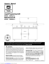
Hardware Pack Parts List for Model M3905ALP & M3905ANG
* Two Batteries/AA included in the Hardware Pack.
PART #PART DESCRIPTIONQTYPURPOSE OF PART
P06002020AHardware Pack1For use in assembly
S112G04081Phillips Head Screw 1/4"x1/2"10
S313G04081Flange Nut 1/4"4
S112G04061Phillips Head Screw 1/4"x3/8"2
S322G04061Cap Nut 1/4"2
S313G03061Flange Nut 3/16"8
P05501017ASide Shelf Lock4
Attaches Side Shelf Brackets To Grill
Attaches Side Shelves to Side Shelf Brackets
Phillips Head Screw 1/4"x1/2"
Qty. 10
Ref.# S112G04081
Flange Nut 1/4"
Qty. 4
Ref.# S313G04081
Phillips Head Screw 1/4"x3/8"
Qty. 2
Ref.# S112G04061
Flange Nut 3/16"
Qty. 8
Ref.# S313G03061
Cap Nut 1/4"
Qty. 2
Ref.# S322G04061
Side Shelf Lock
Qty. 4
Ref.# P05501017A'
Scale: 1:2

5
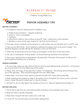
Parts Diagram for Model M3905ALP & M3905ANG

6
KEYDESCRIPTIONPART#QTY
1Lid AssemblyY01100361
1ALid HingeP05332003A2
2Temperature GaugeP00601171A1
3Lid Handle Bracket, LeftP00301016E1
4Lid Handle Bracket, RightP00302016E1
5Lid HandleP00205061A1
6Lid Handle Heat-Insulating SpacerP06801002A2
7Protective PadP05518002I4
8Cooking Rack/SecondaryP01517003B1
9Cooking GridP01604009B4
10Savor Plate, CeramicP01804006A9
11Savor Plate, RackP01717003E3
12Burner/Main P02008004A3
13Gas Collector Box with Electrode P02609001B3
14Infrared Burner AssemblyP02005004A1
15Infrared Burner Electrode P02614010C1
16Infrared Burner ThermocoupleP05305008A1
17Infrared Burner Electrode BracketP03328016C1
18Infrared Burner Electrode ProtectorP06909003C1
19Control Panel, UpperP02909091S1
Control Panel, Lower (LPG only)P02910106B1
Control Panel, Lower (NG only)P02910116G1
21Electric Ignitor, 4-portP02502134C1
22Control Knob SeatP03415014A5
23 Control Knob with Rubber Ring for Main Burner P03411053L 3
24 Control Knob with Rubber Ring for Back/Infrared Burner P03411063L 2
25Name PlateP00414005Q1
26Electric Ignitor, 2-portP02502192C1
Gas Valve/Manifold Assembly (LPG only)Y00601901
Gas Valve/Manifold Assembly (NG only)Y00601911
28Electric Wire SetP02615074A1
29Grease Draining PlateP06902003C2
30Grease TrayP02705165B1
31Grease Tray Heat Shield, LowerP06903028A1
32Grease Tray HandleP00213001B1
33Bowl Partition PanelP07523002A1
34Bowl Panel, LeftP0072043EC1
35Bowl Panel, RightP0072143EC1
36Bowl Panel, FrontP0073843DC1
37Bowl Panel, RearP0072543DC1
38Grease Tray Heat Shield, UpperP06903029A1
39Grease Tray Heat Shield, ExtensionP06903030B1
40Burner BracketP02203114A1
41Back Burner AssemblyY03100181
Back Burner Orifice (LPG only)P06527001A1
Back Burner Orifice (NG only)P06527002A1
20
27
42
Parts List for Model M3905ALP & M3905ANG

7
Parts List for Model M3905ALP & M3905ANG
KEYDESCRIPTIONPART #QTY
43Back Burner Extension TubeP03717019A1
44Back Burner ElectrodeP02614011C1
45Back Burner ThermocoupleP05305009A1
46Back Burner Electrode ProtectorP03328016C1
47Back Burner Electrode BracketP06909004C1
48Back Burner Wind ShieldP06905012B1
49Cart Rear Wind ShieldP06906018C1
50Regulator with Hose (LPG)P03631001A1
51Side ShelfP01105002B2
52Side Shelf Bracket, LeftP01209003A1
53Side Shelf Bracket, RightP01210003A1
54Side Shelf LockP05501017A4
55Bowl BracketP03306015C1
56Door, LeftP04302025A1
57Door, RightP04303025A1
58Door HandleP00214028H2
59Door Bracket, LeftP03314009C1
60Door Bracket, RightP03314010C1
61Bowl Support BracketP01303004B2
Cart Side Panel, Left (LPG only)P07602010A1
Cart Side Panel, Left (NG only)P07602011A1
63Cart Side Panel, RightP07603010A1
Cart Bottom Shelf (LPG only)P01009006C1
Cart Bottom Shelf (NG only)P01009007C1
65Cart Rear Panel P07701044A1
66Cart SupportP01907005B1
67Door MagnetP05523001K4
68Tank Pull-Out Tray AssemblyY03400381
69Caster Seat, LFP05327009T1
70Caster Seat, LRP05327010T1
71Caster Seat, RFP05327011T1
72Caster Seat, RRP05327012T1
73Caster, 2.5 in., with BrakeP05110004D4
Cart Spice Basket (LPG only)P05204005B1
Cart Spice Basket (NG only)P05204005B2
75Lighting StickP05507031E1
76Regulator Assembly / NGY0800071
77Hose, 12ft. / NGP03703001A1
78Extension Hose / NGP03705020A1
79Door Guide PlateP05510014A1
Hardware PackP06002020A1
Operator's ManualP80108001H1
Grill CoverP07007016A1
62
64
74
To obtain the correct replacement parts for your gas grill, please refer to the part numbers in this parts
list. The following information is required to ensure you receive the correct parts:
1. Model and Serial Number (see CSA label on grill)
2. Part Number
3. Part Description
4. Quantity of parts needed
Important: Use only factory authorized parts. The use of any part that is not factory authorized can be
dangerous and will also void your product warranty. Keep this Operator's Manual for convenient referral
and for part replacement.
For the repair or replacement parts you need:
Call our Grill Information Center at 1-800-770-9769

8
Y0250076 Rotisserie Assembly Parts Diagram
Y0250076 Rotisserie Assembly Parts List
Grill Information Center: If you have questions about assembly or grill operation, or
if there are damaged or missing parts when you unpack this unit from the shipping box, call us
8:00 am - 4:30 pm CST, Monday through Friday at: 1-800-770-9769
KEY
PART#
DESCRIPTION
QTY
Hardware for Rotisserie
9
10
11
7
4
8
3
3
6
3
2
1
5
Rot. Handle
Rot. Bushing
Rot. Thumbscrew 3/8"x1/2"
Rot. Collar
Rot. Spit
Rot. Holding Fork
Rot. Motor Bracket
Rot. Motor/AC
Rot. Screw #10-24x3/4"
Rot. Washer
Rot. Nut #10-24
1.
2.
3.
4.
5.
6.
7.
8.
9.
10.
11.
1
1
3
1
1
2
1
1
2
2
2
P05508004E
P05508092F
S196G06084
P05508091F
P05508145F
P05508090F
P03307028A
P07101008B
S112G10124
S411G03084
S362G10124
Rot. Screw#10-24x3/4"
UNC
QTY. 2
Ref.# S112G10124
Rot. Thumbscrew
3/8"x1/2"
QTY. 3
Ref.# S196G06084
Rot.Washer
QTY. 2
Ref.# S411G03084
Rot. Nut.#10-24
QTY. 2
Ref.# S362G10124

9
Assembly Instructions
Phillips Head Screw 1/4"x1/2"
Qty. 10
Ref.# S112G04081
Flange Nut 1/4"
Qty. 4
Ref.# S313G04081
Phillips Head Screw 1/4"x3/8"
Qty. 2
Ref.# S112G04061
Cap Nut 1/4"
Qty. 2
Ref.# S322G04061
1
Install Side Shelf Brackets
Align the holes on Right Side Shelf Bracket with the
threaded holes and holes on right side of grill. Tighten
securely using 6 Screws and 3 Nuts provided.
Repeat for Left Side Shelf Bracket.
2
Install Side Shelves
Flange Nut 3/16"
Qty. 8
Ref.# S313G03061
Side Shelf Lock
Qty. 4
Ref.# P05501017A
Scale: 1:2
Install Right Side Shelf to Right Side Shelf Bracket.
Tighten securely using 2 Locks and 4 Nuts provided.
Repeat for Left Side Shelf.

10
Install Ignitor Battery
3
Unscrew Ignitor Cap from Control Panel.
Place supplied AA battery into the Ignitor
Slot with positive pole facing you.
Position the Cap and Spring over the AA
battery and tighten onto Control Panel.
Repeat to install the other AA battery
into the Ignitor Slot.
WARNING
!
Failure to read and follow the Use and Care
Instructions could result in a fire or explosion
that could cause serious bodily injury, death or
property damage.
!
Final Grill Assembly Step
When you have finished assembling your
grill be sure that all screws are tightened
for safe operation of your grill.
Install Cooking Components
5
With the assistance of another person,
perform this Electrode Check before
proceeding.
4
Be sure all Control Knobs are set to
"OFF" and open the Grill Lid.
Have your assistant stand behind to the
right of the grill and look toward the front
of the grill bowl. Never put your face
inside the Grill Head.
Turn any Main Burner Control Knob to
IGN and push in. You should hear a
"clicking" sound. Your assistant should
see a blue spark within each Gas
Collector Box. If a spark is present the
Electrode Tips are properly positioned.
If no spark is seen, the Spark Gap
needs to be adjusted as follows:
Gas Collector Box
Spark Electrode Tip
Spark Gap
Inside Nut
Spark Receiver
This test will ensure that the Spark Electrode Tips
are properly positioned so your grill lights easily
and properly.
Place the Ceramic Savor Plates™ on
the Savor Plate™ Rack and place on the
lower ledge above the Burners.
Place the Cooking Grids on the ledge
above the Ceramic Savor Plates™.
Place the Secondary Cooking Rack into
the holes on the upper left and right of
the Back Burner frame with the bottom
resting in the slots on either side of the
Grill Bowl.
•
•
•
Using an adjustable wrench, loosen the
Inside Nut until the Gas Collector Box can
be turned upward.
If the gap between the Spark Elec-
trode Tip and Receiver is more than
3/16" use long nose pliers to gently
squeeze the Gas Collector Box to
narrow gap.
Return the Gas Collector Box to its
original position, secure the Inside Nut
and try the Electrode Check again. If no
"clicking" sound is heard:
AA Battery may be installed backwards.
Electric wires may be loose. Remove
the AA Battery and inspect the Ignitor
Junction Box found behind the Control
Panel and reconnect any loose wires.
•
•

11
USE AND CARE INSTRUCTIONS
CORRECT LP GAS TANK USE
LP Gas grill models are designed for use with a
standard 20 lb. Liquid Propane Gas (LP Gas) tank,
not included with grill. Never connect your gas grill to
an LP Gas tank that exceeds this capacity. A tank of
approximately 12 inches in diameter by 18-1/2 inches
high is the maximum size LP Gas tank to use. You
must use an "OPD" gas tank which offers a listed
Overfill Prevention Device. This safety feature
prevents tank from being overfilled which can cause
malfunction of LP Gas tank, regulator and/or grill.
Never connect an unregulated LP gas tank to your
gas grill. The gas regulator assembly supplied with
your gas grill is adjusted to have an outlet pressure
of 11" water column (W.C.) for connection to an LP
gas tank. Only use the regulator and hose assembly
supplied with your gas grill. Replacement regulators
and hose assemblies must be those specified by
the Manufacturer.
Have your LP Gas dealer check the release valve
after every filling to ensure it remains free of defects.
Always keep LP Gas tank in upright position.
Do not subject the LP Gas tank to excessive heat.
Never store an LP Gas tank indoors. If you store
your gas grill in the garage always disconnect the
LP Gas tank first and store it safely outside.
LP Gas tanks must be stored outdoors in a well-
ventilated area and out of the reach of children.
Disconnected LP Gas tanks must not be stored in a
building, garage or any other enclosed area.
The regulator and hose assembly can be seen after
opening the doors (if applicable) and must be
inspected before each use of the grill. If there is
excessive abrasion or wear or if the hose is cut, it
must be replaced prior to using the grill again.
Never light your gas grill with the lid closed or
before checking to ensure the burner tubes are fully
seated over the gas valve orifices.
Never allow children to operate your grill. Do not
allow children or pets to play near your grill.
The LP Gas tank must be constructed and marked
in accordance with the Specifications for LP-Gas
Cylinders of the U.S. Department of Transportation
(D.O.T.) or the National Standard of Canada, CAN/
CSA-B339, Cylinders, Spheres and Tubes for
Transportation of Dangerous Goods; and
Commission, as applicable.
The LP Gas tank must have a shutoff valve,
terminating in an LP Gas supply tank valve outlet,
that is compatible with a Type 1 tank connection
device. The LP Gas tank must also have a safety
relief device that has a direct connection with the
vapor space of the tank.
The tank supply system must be arranged for vapor
withdrawal.
The LP Gas tank used must have a collar
to protect the tank valve.
WARNING
!!
Do not store a spare LP-Gas tank under or near
this appliance.
Never fill the tank beyond 80 percent full; and
If the information in "(a)" and "(b)" is not followed
exactly, a fire causing death or serious injury may
occur.
A.
B.
C.
•
•
•
WARNING
! !
Use your grill at least 3 feet away from any
wall or surface. Use your grill at least 3 feet
away from combustible objects that can melt
or catch fire (such as vinyl or wood siding,
fences and overhangs) or sources of ignition
including pilot lights on water heaters and live
electrical appliances.
Never use your gas grill in a garage, porch, shed,
breezeway or any other enclosed area.
Never obstruct the flow of ventilation air around
your gas grill housing.
Use of alcohol or drugs may impair the ability to
assemble and operate the appliance.
Keep fire extinguisher readily accessible. In the
event of a oil/grease fire, do not attempt to
extinguish with water. Use type B extinguisher
or smother with dirt, sand or baking soda.
In the event of rain, cover the grill and turn off
the burner and gas supply.
Use your grill on a level, stable surface in an
area clear of combustible materials.
Do not leave grill unattended when in use.
Do not move the appliance when in use.
Allow the grill to cool before moving or storing.
Do not use your grill as a heater.
This grill is not intended to be installed in
or on recreational vehicles and/or boats.

12
USE AND CARE INSTRUCTIONS
NOTE about LP Gas Tank Exchange Programs
Many retailers that sell grills offer you the option of
replacing your empty LP Gas tank through an exchange
service. Use only those reputable exchange compa-
nies that inspect, precision fill, test and certify their
tanks. Exchange your tank only for an OPD safety
feature-equipped tank as described in the LP Gas tank
section of this manual.
Ÿ
How to Leak Test your LP Gas Tank
LP Gas Model only:
Connect Regulator with Hose to your LPG Tank
LP Gas Model only:
Secure a 20lb LP Gas Tank to Gas Grill
Turn your LP Gas Tank Valve clockwise to the
closed or OFF positon.
Place LP Gas tank into tank hole on bottom shelf
or (on select models) slide the Tank Tray out of
the cabinet until it is fully extended. The Tank Tray
has an auto lock position and may need to be
pulled firmly.
Install the tank so the Tank Valve faces the rear
right corner of cabinet.
Screw the Wing Bolt in to secure the gas tank.
If growing bubbles appear do not use or move
the LP Gas tank. Contact an LP Gas Supplier
or your fire department!
WARNING
!
!
Use a clean paintbrush and a 50/50 mild soap and
water solution.
Brush soapy solution onto LP Gas tank in the areas
indicated by the arrows. See diagram.
If growing bubbles appear do not use or move the
LP Gas tank. Call an LP Gas Supplier or your Fire
Department.
All leak tests must be repeated each time your LP Gas
tank is exchanged or refilled.
When checking for gas leaks do not smoke.
Do not use an open flame to check for gas leaks.
Your grill must be leak tested outdoors in a well-
ventilated area, away from ignition sources such as
gas fired or electrical appliances. During the leak test,
keep your grill away from open flames or sparks.
Do not use household cleaning agents. Damage to
gas assembly components can result.
Ÿ
Ÿ
Ÿ
Ÿ
Ÿ
Wing Bolt 5/16"x4-1/2"
Qty. 1
Ref. # S233G05461
Ÿ
Ÿ
For your safety:
Leak test new and exchanged LP Gas tanks BEFORE
connecting one to your grill.
Always keep new and exchanged LP Gas tanks in an
upright position during use, transit or storage.
Turn all Burner Valves to the OFF position.
Inspect the valve connection port and regulator
assembly for damage or debris. Remove any
debris. Never use damaged or plugged equipment.
Connect the regulator assembly to the tank valve
and HAND TIGHTEN nut clockwise to a full stop.
DO NOT use a wrench to tighten because it could
damage the Quick Coupling Nut and result in a
hazardous condition.
Open the tank valve 1/4 to 1/2 (counterclockwise)
and use a soapy water solution to check all
connections for leaks before attempting to light
your grill. See "Checking for LP Gas Leaks". If
a leak is found, turn the tank valve off and do not
use your grill until the leak is repaired.
Type 1 connection per
ANSI Z21.58b-2002
Quick
Coupling Nut
CAUTION: When the appliance is not in use the gas
must be turned off at the tank.

13
USE AND CARE INSTRUCTIONS
Disconnecting A Liquid Propane Gas (LPG)
Tank From Your Grill
Make sure the Burner Valves and LP Gas tank
valve are off. (Turn clockwise to close.)
Detach the hose and regulator assembly from
the LP Gas tank valve by turning the Quick
Coupling Nut counterclockwise.
WARNING
!!
If you have a gas leak that cannot be repaired
by tightening, turn off the gas at the source,
disconnect fuel line from your grill and call
1-800-770-9769
or your gas supplier for repair
assistance.
Check all connections for LP Gas Leaks
Never test for leaks with a flame. Prior to first use,
at the beginning of each season, or every time
your LP Gas tank is changed, you must check for
gas leaks. Follow these three steps:
Make a soap solution by mixing one part liquid
detergent and one part water.
Turn the grill Control Knobs to the full OFF
position, then turn the gas ON at source.
Apply the soap solution to all gas connections
indicated by the arrows. See diagram. If
bubbles appear in the soap solution the
connections are not properly sealed. Check
each fitting and tighten or repair as necessary.
Regulator with Hose (LPG)
LP Gas Tank
Gas Valve / Manifold Assembly

14
USE AND CARE INSTRUCTIONS
Natural Gas Model only:
Connecting Natural Gas To Your Grill
WARNING
!!
If you have a gas leak that cannot be repaired
by tightening, turn off the gas at the source,
disconnect fuel line from your grill and call
1-800-770-9769
or your gas supplier for repair
assistance.
Check all connections for NG Leaks
Never test for leaks with a flame. Prior to first use,
at the beginning of each season, you must check
for gas leaks. Follow these three steps:
Make a soap solution by mixing one part liquid
detergent and one part water.
Turn the grill Control Knobs to the full OFF
position, then turn the gas ON at source.
Apply the soap solution to all gas connections
indicated by the arrows. See Fig. 3. If bubbles
appear in the soap solution the connections
are not properly sealed. Check each fitting and
tighten or repair as necessary.

15
USE AND CARE INSTRUCTIONS
Grill Lighting Instructions
Before each use, check all hoses for cracks, nicks, cuts,
burns or abrasions. If a hose is damaged in any way, do
not use your grill before replacing the hose with an
authorized part from the Parts List. Also make sure all
gas supply connections are securely tightened.
Familiarize yourself with the safety and Use and Care
instructions in this manual. Do not smoke while lighting
grill or checking gas supply connections.
Be sure the LP Gas tank is filled or the Natural Gas Line
is attached to the gas source. .
Open the Grill Lid.
Check that the end of each Burner Tube is properly
located over each Valve Orifice.
5.
4.
3.
2.
1.
Infrared Burner Lighting Instructions
Follow steps 1 through 6 of the Grill Lighting
Instructions.
Push and turn the Control Knob to IGN. Push the
Control Knob in to automatically ignite the Burner.
Once the burner is lit, turn the knob back to High,
keep pressing the knob and holding it for at least
10 seconds before releasing.
After Burner is lit, turn the tank valve SLOWLY one
more 1/4 of a turn for 1/2 of one complete turn.
1.
3.
2.
Back Burner Lighting Instructions
Follow steps 1 through 6 of the Grill Lighting
Instructions.
Push and turn the Control Knob to IGN. Push the
Control Knob in to automatically ignite the Burner.
Once the burner is lit, turn the knob back to High,
keep pressing the knob and holding it for at least
10 seconds before releasing.
1.
3.
2.
After Burner is lit, turn the tank valve SLOWLY one
more 1/4 of a turn for 1/2 of one complete turn.
Burner Control Knobs on Control Panel
Failure to replace a faulty hose, secure gas supply
connections or to open the Lid before proceeding
to the Lighting Procedures could result in a fire
or explosion that could cause serious bodily injury,
death, or property damage.
WARNING
!
!
Set Control Knobs to OFF and open the LP Gas
SLOWLY 1/4 of a turn. For Natural Gas
open the Shut Off Valve at source.
Push and turn RIGHT Mai n Burne r C ontrol Knob t o
I GN. Push the Control Knob in to automatically ignite
the Burner.
If ignition does not occur in 5 seconds, turn the
burner Control Knob(s) and gas source OFF and
conduct a leak test of ALL gas connections and gas
sources as explained in the Use and Care section
of this manual. If no leaks are detected, wait 5
minutes for any gas to clear and repeat the lighting
procedure.
After Burner is lit, turn the knob back to High (or Low)
and turn the tank valve SLOWLY one more 1/4 of a
turn for 1/2 of one complete turn.
Once one Main Burner is lit, the adjacent Main
Burner can be lit by turning its Control Knob to HIGH.
6.
tank valve
OFF
LO
IGN
HI
7.
OFF
Open LP
gas tank
10.
9.
8.
INFRARED
BURNER
BACK
BURNER
R
R
MAIN
BURNER
OFF
HI
IGN
OFF
HI
IGN
Push and turn

16

17
Rotisserie Instructions
1.
Remove all components from the carton.
Attach the Motor Bracket on the outside of the right grill bowl panel. Align the two holes of the
Bracket with the holes on the grill bowl. Tighten securely using two Screws #10-24x3/4" UNC, Plain
Washers and Nuts provided.
2.
Slide a Holding Fork onto each end of the Rotisserie Spit. Adjust spacing between Holding Forks to
accommodate your food, then tighten the Thumbscrews to keep the Holding Forks in position. Slide
the Collar and Bushing onto the threaded end of the Spit. Do not tighten the Collar Thumbscrew until
the Rotisserie is placed into your grill. Last, screw the Handle onto the threaded end of Rotisserie
Spit as shown.
3.
Rot. Screw #10-24x3/4" UNC x2
Rot. Washer x2
Rot. Nut #10-24 x2
Spit
Holding Forks
Thumbscrew
3/8"x1/2"
Collar
Bushing
Handle
Thumbscrew
3/8"x1/2"
Rot.Thumbscrew 3/8"x1/2" x3
Washer#10-24 Nut.
Rot. Screw#10-24x3/4"
UNC with
washers and nuts
Outside of left grill
bowl panel
Motor Bracket

18
Install the AC (alternating current) Rotisserie Motor onto the Motor Bracket as shown below. Be sure
the Motor attaches to the Bracket with the electrical cord down. This installation insures that once
the Spit is inserted into the Motor it will also rest securely into the slot of your grill bowl.
4.
Insert the assembled Rotisserie into the Motor as shown below. The Motor should be on the right
side of your grill and the Handle on the left side. Place the Bushing into the slot opening on the
left side of your grill bowl, then tighten the Collar Thumbscrew to the right of the Bushing. The Collar
will stabilize the Rotisserie during the cooking process and the Bushing allows the Rotisserie Spit to
turn smoothly. Plug the Rotisserie into an outlet and turn on to test.
5.
BEFORE rotisserie cooking you will need to remove the Cooking Grid(s) and possibly the Ceramic
Savor Plates™ from your grill. When rotisserie cooking place a Cooking Pan under the food to be
cooked. This will capture the drippings and keep your grill clean of excess grease which could cause
a fire. Use caution when moving a Cooking Pan containing hot oils.
The Bushing and Collar must always be used with this Rotisserie.
Handle
Bushing
Collar
Thumbscrew
Spit
Holding Forks
Thumbscrew
Motor
Rotisserie Motor
Motor Bracket
Rotisserie Spit must rest securely
into the slot of your grill bowl.

19
Proper care and maintenance will keep your grill in top
operating condition and prolong its life. Follow these
cleaning procedures on a timely basis and your grill will
stay clean and operate with minimum effort.
CAUTION: Be sure your grill is OFF and cool before cleaning.
Cleaning The Cooking Grids
Before initial use, and periodically, wash your
Cooking Grids in a mild soap and warm water
solution. You can use a wash cloth or vegetable
brush to clean your Cooking Grids.
Cleaning The Ceramic Savor Plates™
Periodically you should wash the Ceramic Savor
Plates™ in a soap and warm water solution. Use a
vegetable brush to remove stubborn burnt-on cooking
residue. Dry the Ceramic Savor Plates™ thoroughly
before you reinstall them into the cooking bowl.
Cleaning The Grease Tray and Receptacle
To reduce the chance of fire, the Grease Draining
Tray and Grease Receptacle (some models)
should be visually inspected before each grill use.
Remove any grease and wash Grease Tray and
Receptacle with a mild soap and warm water
solution.
Cleaning the Inside of the Grill Lid
Grease can have a tendency to build up on the
inside of the Grill Lid and could drip onto deck or
patio when the lid is opened. Visually inspect the
inside of the Grill Lid before each grill use. Remove
any grease and wash with a mild soap and warm
water solution.
Annual Cleaning of The Grill Interior
Burning-off excess food after every cookout will
keep it ready for instant use. However,at least every
3 months you must give the entire grill a thorough
cleaning to minimize your risk of grease fire and
keep the grill in top shape. Follow these steps:
Turn all Burner Valves to the full OFF position.
Turn the LP gas tank valve to the full OFF position.
For Natural Gas shut off valve.
Disconnect the regulator from the gas tank. Inspect
the hose with regulator assembly for cracking, cuts
or any other damage, and replace as neccessary.
Refer to the Parts List in this Operator's Manual.
Remove and clean the Ceramic Savor Plates™,
Cooking Grids, Cooking Rack and Grill Burners.
Cover each Gas Valve Orifice with aluminum foil.
Brush the inside and bottom of the grill with a fiber
pad or nylon brush and wash with a mild soap and
warm water solution. Rinse thoroughly and let dry.
Remove aluminum foil from Orifices and check
each Orifice for obstruction.
Check each Spark Electrode, adjusting as needed.
The space between the Spark Electrode Tip and
Spark Receiver should be approximately 3/16".
Replace the Burners and adjust the Gas
Collector Box. The edge of the collector box should
be overlapping the Burner Port.
CLEANING AND MAINTENANCE
1.
2.
3.
4.
5.
6.
7.
8.
9.
10.
11.
Cleaning Exterior Surfaces:
Before initial use, and periodically thereafter, we
suggest you wash your grill using a mild soap and
warm water solution. You can use a wash cloth or
sponge for this process. Do not use a stiff wire or
brass brush. These will scratch stainless steel and
chip painted surfaces (varies by model) during the
cleaning process.
Cleaning Exterior Stainless Steel Surfaces:
Weathering and extreme heat can cause exterior
stainless steel surfaces to turn tan in color. Machine
oils used in the manufacturing process of stainless
steel can also cause this tanning color. After remov-
ing any protective PVC film from the Grill Lid and
Control Panel use a Stainless Steel Cleaner to polish
the stainless steel surfaces of your grill. Never use
abrasive cleaners or scrubbers because they will
scratch and damage your grill. Follow these steps for
the best results.
1. Turn the LP Gas tank valve (clockwise) to the full
OFF position. Disconnect the regulator and hose
assembly from LP Gas tank. For Natural Gas shut
off valve and disconnect the NG regulator and hose
from valve. Cover exposed gas fitting with
aluminum foil.
2. Remove dirt or grease using a soft cloth and
polish stainless surfaces. Wipe with a soft cloth.
3. Remove aluminum foil from exposed gas fitting
and allow grill to air dry before attaching the
regulator and hose to your LP Gas tank, or
attaching the regulator and hose to Natural Gas
valve.
Replace Ceramic Savor Plates™ and Cooking Grids.
Reconnect the gas source and observe the
Burner flame for correct operation.
Keep grill area clear and free from combustible
materials, gasoline and other flammable vapors
and liquids.
Do not obstruct the flow of air for combustion
and ventilation.
Keep the ventilation openings of the tank enclosure
cabinet free and clear of debris.
Visually check burner flames occasionally to
ensure proper flame pattern as shown below.
Failure to comply with these instructions may
result in a hazardous situation which, if not
avoided, may result in injury.
MAGNIFIED VIEW OF
BURNER FLAME
THROUGH LIGHTING
HOLE
CAUTION
! !

20
CLEANING THE BURNER TUBES AND BURNER PORTS
To reduce the chance of FLASHBACK FIRE you must
clean the Burner Tubes as follows at least once a month
in summer and fall or whenever spiders are active in your
area, and if your grill has not been used for an extended
period of time.
1. Turn all Burner Valves to the full OFF position.
2. Turn the LP Gas tank valve to the full OFF position.
For Natural Gas shut off NG valve.
3. Detach the LP Gas regulator assembly from your
gas grill. For Natural Gas detach NG regulator from
your grill.
4. Remove the Cooking Grids and Ceramic Savor
Plates™ from your grill.
5. Remove the cotter pin from the rear of each Main
Burner using long nose pliers. Remove screws
along all sides of the Infra-red Burner using
a Phillips Head Screwdriver.
6. Carefully lift each Burner up and away from the
Gas Valve Orifice.
7. Check and clean burner/venturi tubes for insects
and insect nests. A clogged tube can lead to a fire
beneath the grill.
8. Refer to Figure 1 and perform one of these
three cleaning methods:
Regardless of which Burner cleaning procedure you
use, we recommend you also complete the following
steps to help prolong Burner life.
1. After each use of the main grill or infra-red cooking
zone it is necessary to burn off food particles and
drippings which can clog Burner ports and reduce
Burner performance. OPEN the grill Lid, ignite the
burner(s) and operate grill on HIGH setting for
3 to 5 minutes. You can close the Lid if only main
Burners are lit, but NEVER close the Lid over a lit
Infra-red Burner.
2. Use a nylon brush, blower or vacuum to remove
accumulated ash from the outer surface of each
Burner. Clogged tube style Burner ports can be
cleaned with a stiff wire, such as an open paper clip.
DO NOT use a stiff brush or sharp tool of any type on
the fragile infra-red Burner.
3. Inspect each Burner for damage (cracks or
holes) and if such damage is found, order and
install a new Burner. After installation, check
to ensure that the Gas Valve Orifices are
correctly placed inside the ends of the Burner
Tubes. Also check the position of your Spark
Electrode.
METHOD 1: Bend a stiff wire or wire coat
hanger into a small hook as shown and
run the hook through the Burner Tube and
inside the Burner several times to remove
debris.
METHOD 2: Use a bottle brush with a
flexible handle and run the brush through
the Burner Tube and inside the Burner
several times to remove any debris.
METHOD 3: Use an air hose to force air
through each Burner Tube. The forced air
should pass debris or obstructions through
the Burner and out the Ports.
9
Figure 1
TO CLEAN BURNER TUBE,
INSERT HOOK AS INDICATED BY THE ARROW
Burner Tube
WARNING
!!
For safe operation ensure the Gas Valve
Assembly Orifice is inside the Burner Tube
before using your grill. See figure. If the Orifice
is not inside the Burner Tube, lighting the
Burner may cause explosion and/or fire result-
ing in serious bodliy injury and/or property
damage.
/