Page is loading ...

Big Vac
72-000-A
SN: 72308
March 2018
Product Support: Hwy SS & Poplar Ave; Cameron WI 54822
1-800-891-9435 productsupport@smithco.com

Introduction Service Diagrams Parts Accessories Reference
CONTENTS
Introduction ...................................................................................1-4
Introduction .................................................................................. 1
Safe Practices ............................................................................. 2
PTO Safety Warnings .................................................................. 3
Specications .............................................................................. 4
Optional Equipment ..................................................................... 4
Service ......................................................................................... 5-11
Maintenance .............................................................................5-6
Overloading Debris Hopper and Vacuum Housing Wear ............ 7
Service Chart .............................................................................. 8
End User’s Service Chart ............................................................ 9
Adjustments .......................................................................... 10-11
Storage ...................................................................................... 11
Diagrams .................................................................................... 12-13
Hydraulic Diagram ................................................................12-13
Parts ...........................................................................................14-31
Big Vac Main ........................................................................ 14-15
Control Panel ........................................................................ 16-17
Oil Tank ................................................................................. 18-19
Blower Housing ....................................................................20-21
Vacuum Housing Belts and Tensioners ...............................22-23
Hopper .................................................................................. 24-25
72-151 Hydraulic Valve ......................................................... 26-27
78-416 3 Bank Hydraulic Valve............................................28-29
72-048 Axle ...........................................................................30-31
72-202 PTO Shaft ................................................................. 30-31
Accessories ...............................................................................32-48
72-001 Combination Sweeper - Verticut Head .....................32-37
72-002 Rubber Finger Sweeper Head ..................................38-41
72-005 Brush Reel Sweeper Head with 72-006 Brush Only 42-45
72-003 Hand Held Vacuum Hose .........................................46-48
Reference ................................................................................... 49-50
Decal List ................................................................................... 49
Quick Reference Replacement Parts ........................................ 50
Warranty ...........................................................Inside Back Cover

1
Introduction
INTRODUCTION
Thank you for purchasing a Smithco product.
Read this manual and all other manuals pertaining to the Big Vac carefully as they contain safety, operating,
assembly and maintenance instructions. Failure to do so could result in personal injury or equipment damage.
Keep manuals in a safe place after operator and maintenance personnel have read them. Right and left sides
are from the operator’s seat, facing forward.
All Smithco machines have a Serial Number and Model Number. Both numbers are needed when ordering
parts. The serial number plate on the Big Vac is located on the front cross memeber on the frame. Refer to
engine manual for placement of engine serial number.
For product and accessory information, help nding a dealer, or to register your product please contact us at
http:\\www.Smithco.com.
Information needed when ordering replacement parts:
1. Model Number of machine
2. Serial Number of machine
3. Name and Part Number of part
4. Quantity of parts
For easy access record your Serial and Model numbers here.
SMITHCO CUSTOMER SERVICE 1-800-891-9435
WARNING
Failure to follow cautious operating practices can re-
sult in serious injury to the operator or other persons.
The owner must understand these instructions, and
must allow only trained persons who understand these
instructions to operate this vehicle.
WARNING:
This vehicle can expose you to chemicals known
to the State of California to cause cancer, birth
defects, and other reproductive harm.
For more information visit
www.P65Warning.ca.gov

2
Introduction
SAFE PRACTICES
1. It is your responsibility to read this manual and all publications associated with this machine (engine, accessories
and attachments).
2. Never allow anyone to operate or service the machine or its attachments without proper training and instructions.
Never allow minors to operate any equipment.
3. Learn the proper use of the machine, the location and purpose of all the controls and gauges before you operate
the equipment. Working with unfamiliar equipment can lead to accidents.
4. Wear all the necessary Personal Protective Equipment (PPE) to protect our head, eyes, ears, hands and feet. Ear
and eye protection are required. Operate the machine only in daylight or in good articial light.
5. Inspect the area where the equipment will be used. Beware of overhead obstructions and underground obstacles.
Stay alert for hidden hazards.
6. Never operate equipment that is not in perfect working order or without decals, guards, shields, or other protective
devices in place.
7. Never disconnect or bypass any switch.
8. Carbon monoxide in the exhaust fumes can be fatal when inhaled, never operate a machine without proper ventila-
tion.
9. Never use your hands to search for oil leaks. Hydraulic uid under pressure can penetrate the skin and cause seri-
ous injury.
10. This machine demands your attention. To prevent loss of control or tipping of the vehicle:
A. Use extra caution in backing up the vehicle. Ensure area is clear.
B. Do not stop or start suddenly on any slope.
C. Reduce speed on slopes and in sharp turns. Use caution when changing directions on slopes.
D. Stay alert for holes in the terrain and other hidden hazards.
E. Operate equipment up and down slopes, never across the face.
11. Before leaving operator’s position for any reason:
A Disengage all drives.
B. Lower all attachments to the ground.
C. Shut engine off and remove the ignition key.
12. Keep hands, feet and clothing away from moving parts. Wait for all movement to stop before you clean, adjust or
service the machine.
13. The rubber ngers, sweeper and vacuum pick up and propel debris and small objects in machines path during
operation. Keep the area of operation clear of all bystanders.
14. Never carry passengers.
15. Use parts and materials supplied Smithco by only. Do not modify any function or part.
16. Avoid sharp turns. Watch the tires of the tractor while turning to make sure they do not contact the tongue of the
Big Vac.
17. Shut down power source before attempting to unclog any part of the machine.
18. If reel deck and/or blower began to vibrate abnormally, immediately shut off power and determine the cause.
19. Always drive at a safe towing speed relative to conditions and ensure that your speed is low enough for an emer-
gency stop to be safe and secure. Smithco recommends a maximum speed of 8mph (12 kph).
These machines are intended for professional maintenance on golf courses, sports turf, and any other
area maintained turf and related trails, paths and lots. No guaranty as to the suitability for any task is
expressed or implied.

3
Introduction
PTO SAFETY WARNINGS
1. Always disengage the PTO, shut off engine and remove the keys before leaving the tractor seat.
2. Keep the tractor's master shield in place at all times.
3. Missing or damaged shielding is the main reason for drive-line entanglement. Keep All Guards on and
in good condition. Check guards frequently.
4. Never step across a rotating power shaft. Always walk around the revolving shaft even if guards are in
place.
5. Dress for safety. Do not wear loose fi tting clothes or jewelry and keep long hair covered or pulled back.
6. The tractor draw-bar should be adjusted to the length specifi ed in the driven machine's manual. This will
help prevent drive-line stress and separation on uneven terrain and in tight turns.
7. A PTO shaft may break or separate during operation if improperly installed or adjusted. Be sure PTO
shaft is installed properly. See image below.
8. Never perform maintenance or adjustments until both the drive-line and the machinery have stopped
moving.
9. Warn anyone who might come near an operating PTO about the entanglement hazard.
10. Regularly test drive-line guards by spinning or rotating them to ensure the have not become stuck to the
shaft.
11. Always use the drive-line recommended for your machine. Never switch drive-lines among diff erent
machines.
12. Reduce PTO shaft abuse by observing the following:
a. Avoid tight turns that pinch rotating shafts between the tractor and machine.
b. Keep excessive telescoping to a minimum.
c. Engage power to the shaft gradually.
d. Avoid over tightening of slip clutches on PTO driven machines.
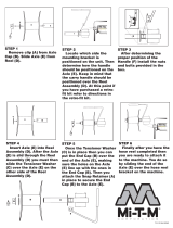
PTO connection with larger guard
housing goes to the tractor.

4
Introduction
SPECIFICATIONS FOR BIG VAC
WEIGHTS AND DIMENSIONS
Length 180" (458 cm)
Width 84" (214 cm)
Height 87" (221 cm)
Weight 3500 lb (1588 kg)
SOUND LEVEL
At Ear Level 92 dB (Use ear protection while operating)
PTO SHAFT
Maximum RPM 540
TIRES & WHEELS Two 26.5 - 1400 x 12 (18 psi (1.3 bar)) Fairway Type Turf Tires
Castor: 13 x 5 x 6 (20 psi (1.4 bar))
FLUID CAPACITY
Hydraulic Fluid 17 gallon (64 liters)
Grade of Hydraulic Fluid SAE 10W-40 API Service SJ or higher Motor Oil
OPTIONAL EQUIPMENT
72-001 Combination Verticut and Sweeper Head
72-002 Rubber Finger Sweeper Head
72-003 25ft Hand Held Vacuum
72-004 Over-the-Road Tow Package
72-005 Nylon Brush Sweeper Head
72-245 2
5
/
16
Ball Hitch

5
Service
MAINTENANCE
Before servicing or making adjustments to machine, stop engine on tow vehicle and
remove key from ignition.
Use all procedures and parts prescribed by the manufacturer's. Read the engine
manual before operation.
LUBRICATION
Use No. 2 General Purpose Lithium Base Grease and lubricate DAILY. The Big Vac has 19 to 25 grease
ttings, depending on what sweeper head you are using. All bearings are sealed bearings. When inserting
grease, be careful not to ruin the seal, if this happens, replace the bearing at once. Be sure to wipe grease
tting clean before injecting grease. Give only one or two pumps of grease at each lubrication.
REF# LOCATION
1 One on all four castor wheels.
2 Four on the front of the blower that go to pillow blocks on blower and PTO shafts.
3 One on each mounted bearing for reel shaft. Two for nger reel. Four for combination head.
4 One on each end of the PTO shaft.
5 One on all four castor wheel mount brackets.
6 One on the jack stand.
7 One on each end of roller - Combination head only.

6
Service
MAINTENANCE (CONTINUED)
TIRE PRESSURE
Caution must be used when inating a low tire to recommended pressure. Over inating can cause tires to
explode. Tires on the machine should be 18 psi (1.3 bar), castor wheels should be 20 psi (1.4 bar). Improper
ination will reduce tire life considerably.
WHEEL MOUNTING PROCEDURE
1. Turn machine off and remove key.
2. Be sure unit is on a level surface. Unhitch from tow vehicle if possible.
3. Block the opposite wheel then the one you are working on.
4. Loosen nuts slightly on wheel to be removed.
5. Jack up machine being careful not to damage underside of machine.
6. Remove nuts, remove wheel.
7. Place new wheel on hub lining up Hex Bolt holes.
8. Torque nuts to 64-74 ft/lb (87-100 Nm) using a cross pattern. Torque again after rst 10 hours and every
200 hours thereafter.
9. Lower machine to ground and remove blocks and jack.
HYDRAULIC OIL
1. Use SAE 10W-40 API Service SJ or higher motor oil.
2. For proper warranty, change oil every 500 hours or annually, which ever is rst and change the lter
after the rst 20 hours, then at 100 hours, then every 250 hours thereafter.
3. Inspect hydraulic lines for damage or leaks. Never use hands to inspect leaks.
4. Check hydraulic uid level in tank. Look at the sight gauge on the front left side of the tank. The oil level
should be at 90°C (194°F). If level is low, add SAE 10W-40 API Service SJ or higher motor oil.
5. After changing oil and/or lter, operate the machine for a few minutes. Check oil level and for leaks.
6. Always use caution when lling hydraulic oil tank or checking level to keep system free of contaminants.
Check and service more frequently when operating in extremely cold, hot or dusty conditions.
7. If natural color of uid is now black or smells burnt, it is possible that an overheating problem exists.
8. If uid becomes milky, water contamination may be a problem.
9. If either of the above conditions happen, change oil and lter immediately after uid is cool and nd
cause. Take uid level readings when system is cold.
10. In extreme temperatures you can use straight weight oil. We recommend SAE 30W API Service SJ or
higher when hot (above 90°F (33°C)) and SAE 10W API Service SJ or higher when cold (below 32°F
(0°C)) ambient temperature. Use either motor oil or hydraulic oil, but do not mix.
11. Oil being added to the system must be the same as what is already in the tank. Mark tank ll area as to
which type you put in.
VERTICUT REEL VALVE HANDLE
If the rubber nger sweeper head is installed on your unit and verticut reel
handle is activated, the hydraulic system may be damaged due to overheating
the oil. Remove the verticut reel valve handle when using the rubber nger
sweeper head (72-002).

7
MAINTENANCE (CONTINUED)
HOPPER LIFT SAFETY
The Hopper Lift Safety is used to support the ram on
the hopper bottom in the extended position so you
may service or repair the machine under the hop-
per. When not in use the Hopper Lift Safety can be
stored on the hopper bed frame.
OVERLOADING DEBRIS HOPPER AND VACUUM HOUSING WEAR
SMITHCO SWEEPER-VACS ARE DESIGNED TO CARRY THE FOLLOWING MAXIMUM LOADS:
Model 72-000 Big Vac 1500 lbs. (608 kg)
PLEASE NOTE THE FOLLOWING:
1. Loads heavier than that will damage the unit.
2. Such damage is not covered by warranty.
3. Overloading is particularly easy when collecting aerier cores.
4. The hoppers on the Big Vac and V62 are large in order to hold 7 and 4 cubic yards respectively, of
thatch, grass clippings, leaves and trash.
5. They will not hold 7 or 4 cubic yards of aerier cores.
6. The maximum depth (in the debris hopper) of aerier cores is:
Model 72-000 Big Vac 12 in. (30 cm)
VACUUM HOUSING WEAR
The Big Vac & V62 are tted with a wear resistant liner in the vacuum housing. This will provide additional
housing life. Be sure the following points are explained to the user:
1. The vacuum housing and impeller must be cleaned each time the unit is used so the housing liner is
inspected daily. Only Smithco Sweeper-Vacs provide a clean out/inspection port for easy inspection and
cleaning.
2. When bare steel is visible at any point in the housing lining, the lining must be replaced. It is expected
the liner will wear and be replaced. It is a vast improvement over competitive units with no liners.
3. Replacement of the liner or the vacuum housing due ti wear is normal and is not covered by warranty.
4. Collection of aerier cores causes extreme wear on the liner (and if unchecked, on the housing).
5. Caution users that, while Smithco Sweeper-Vacs do an excellent job collecting cores, the lining (and the
housing) will wear quickly in such use.
RUBBERIZED BOOT
The rubberized boot between main unit and sweeper head is subject to wear and damage from debris. Unless
defective, replacement of this boot is not covered by warranty.

8
Service
SERVICE CHART
Before servicing or making adjustments to the machine, stop engine, set park
break, block wheels and remove key from ignition.
Follow all procedures and ONLY use parts prescribed by the manufacturer.
Read the engine manual before maintenance.
The suggested maintenance checklist is not offered as a replacement for the manufacturer’s engine manual
but as a supplement. You must adhere to the guidelines established by the manufacturer for warranty cover-
age. In adverse conditions such as dirt, mud or extreme temperatures, maintenance should be more frequent.
Maintenance Service Interval Maintenance Procedure
Aer the rst 5 operating hours Torque the wheel lug nuts. (64-74 /lb (87-100 Nm))
Grease PTO Sha
Before each use daily Check guards on PTO Sha
Open trap door and inspect Blower Housing
Check the tire pressure.
Inspect and clean the machine.
Every 100 Hours Lubricate machine.
Torque the wheel lug nuts. (64-74 /lb (87-100 Nm))
Check belt tension.
Every 400 hours or yearly Check hydraulic Lines.
Clean Blower Housing.1
Check Boot for cracks or rips.
Lubricate machine.
1 In dusty conditions or when airborne debris is present, clean more oen.

9
Service
END USER'S SERVICE CHART
Maintenance Check Item For the week of:
Mon Tues. Wed. urs. Fri. Sat. Sun.
Check the PTO Sha guards
Check the engine oil level.
Check the condition of the Blower Hous-
ing
Clean the debris from pulleys and belts
Check the tire pressure (18 psi)
Check the Instrumentation
Inspect hydraulic system
Lubricate Machine and Booms
Ensure all warning decals are intact.
Areas of Concern
Inspection Performed by:
Item Date Information

10
Service
ADJUSTMENTS
ADJUSTMENT OF BELT TENSIONER
There are four maximum belt tensioners on the Big Vac.
Two control the tension on the belts on the blower housing,
one each on the nger reel and the thatcher reel. The prop-
er tension of the idler should be 12 to 15 as per the gauge
(A) on the side of the tightener. Over tightening the belt will
shorten the life of the belt and the machine may not perform
to the best of its ability. To adjust belt tensioner, loosen Hex
Bolt holding tensioner. Bring idler pulley tight to belts and
turn tensioner into belts to 15°. Tighten holder Hex Bolt.
CONTROL PANEL ADJUSTMENT ARM
On the right hand side of machine is
the adjustment lock arm, by lifting up
you can adjust the control panel by
moving it forward or rearward. Make
certain that the lock arm is locked back
in place after adjustment. For up and
down adjustment loosen the four ad-
justment Hex Bolts place the control
panel to where you want it and tighten
the four Hex Bolts.
HITCH OPTIONS
You may use the clevis hitch that is
shipped with your machine or a 2
5
/
16
ball hitch that is an optional accessory.
Both mount in the same location with
three different Hex Bolt hole options.
VERTICUT REEL VALVE HANDLE
If the rubber nger sweeper head is installed on your unit and verticut reel
handle is activated, the hydraulic system may be damaged due to overheating
the oil. Remove the verticut reel valve handle when using the rubber nger
sweeper head (72-002).

11
Service
ADJUSTMENTS
CASTOR WHEELS
The castor wheel height spacers are quick spacers
meaning they have a slot cut out of them. The castor
fork shaft has two ats on it near the bottom. To re-
move the quick spacers (A) lift up on the castor wheel
(C) and remove lynch pin (B). Let the castor wheel
come down some, take the quick spacer up and turn
it until you feel the ats on the shaft then pull out.
This removes the spacers below the castor arm (D),
reverse the procedure to add spacers. The thin quick
spacers must not be placed in line with the ats on
the shaft or they will fall out. Check the tire pressure
on castor wheels, they should be 20 psi (1.4 bar).
DOUBLE REEL HOUSING
Normal setting is three slots down in front and two
slots down in rear (both sides). You may want to
change the normal setting to compensate for wear of the ail blades or sweeper ngers or to sweep without
cutting. To do this loosen Hex Bolt (E) and remove Hex Bolts (F) both sides. Then tip the reel housing to the
desired position. Replace Hex Bolts and tighten all Hex Bolts. This can also be done in conjunction with the
castor wheel height adjustment spacers.
ANTI SCALP ROLLER (DOUBLE REEL)
Normal setting for the anti scalp roller is with the machine on a
level hard surface. Normal setting is with the bottom of the roller
to be ¼ inch above the ail blades, with ail blades in their lowest
position. To adjust loosen the four Hex Bolts (G) both sides and
slide the roller up or down. Tighten all Hex Bolts.
SINGLE REEL HOUSING
Normal setting is two slots down (H) both front and rear (both
sides).
STORAGE
1. Before storing clean machine thoroughly.
2. Check Hex Bolts and nuts, tighten as necessary.
3. Make all repairs that are needed and remove any debris.
4. Store in a clean and dry area.

12
Diagrams
HYDRAULIC DRAWING

13
Diagrams
HYDRAULIC PARTS LIST
REF# PART# DESCRIPTION QUANTITY
1 72-079 Suction Hose 2
2 18-276 Tee Fitting, 1
1
/
4
1
3 72-146 Filter 1
60-334 Filter Element (replacement only) 1
4 72-041 Hydraulic Tank 1
5 73-029 Hydraulic Hose 1
6 18-447 Run Tee 1
7 72-065 Hydraulic Hose 1
8 72-040 Cylinder 1
72-040-01 Seal Kit 1
72-040-02 Pin with Clips (part of 72-040) 2
9 72-064 Hydraulic Hose 1
10 72-071 Hydraulic Hose 2
11 10-187 Hydraulic Cylinder 1
14-273 Seal Kit 1
12 72-074 Hydraulic Hose 2
13* 72-187 Hydraulic Motor (Thatch Reel) 1
72-186-01 Seal Kit 1
14 72-066 Hydraulic Hose 1
15 72-074 Hydraulic Hose 1
16* 72-186 Hydraulic Motor (Reel) 1
72-186-01 Seal Kit 1
17 72-075 Hydraulic Hose 1
18 72-043 Quick Coupler ½ Male End 4
72-046 Quick Coupler ½ Female End 4
HRR-150 Retaining Ring 1½" External 8
19 72-068 Hydraulic Hose 2
20 72-067 Hydraulic Hose 2
21 72-069 Hydraulic Hose 1
22 72-151 Hydraulic Valve 1
23 78-416 Hydraulic 3 Bank Valve 1
24 72-062 Hydraulic Hose 1
25* 72-185 Hydraulic Double Pump 1
78-413-01 Front Pump Seal Kit 1
72-185-01 Rear Pump Seal Kit 1
* No other parts are replaceable for hydraulic motor or pump.
HYDRAULIC PRESSURES FRONT REAR
Pump Displacement .90 in
3
/rev .40 in
3
/rev
Pump Input Speed (up to) 4000 rpm 4000 rpm
Max. Operating Pressure 3600 psi 3600 psi
Max. Inlet Vacuum 10 in. Hg 10 in. Hg
Max. Case Pressure 80 psi 80 psi

14
Parts
BIG VAC MAIN DRAWING

15
Parts
BIG VAC MAIN PARTS LIST
REF# PART# DESCRIPTION QUANTITY
1 HCP-12-175 Clevis Pin,
1
/
2
x 1
3
/
4
2
HP-18-100 Cotter Pin,
1
/
8
x 1 2
2 72-110 Hopper Chute 1
3 72-111 Middle Chute 1
4 73-061 Reel Lift Cross Bar 1
HB-12-13-125 Hex Bolt,
1
/
2
- 13 x 1
1
/
4
2
HNTL-12-13 Nylon Lock Nut
1
/
2
- 13 2
5 72-081 Vacuum Housing 1
6 72-109 Blower Chute 1
7 72-041 Hydraulic Oil Tank 1
8 HSTP-516-18-075 Phillips Truss Head Machine Screw
5
/
16
- 18 x
3
/
4
6
9 72-143 Front PTO Cover 1
78-274 Cage Nuts 6
10 72-202 PTO Shaft 1
11 78-244
3
/
4
" Clevis 1
12 78-240 Jack 1
13 72-149 Right PTO Cover Bracket 1
72-150 Left PTO Cover Bracket 1
14 HB-12-13-150 Hex Bolt,
1
/
2
-13 x 1
1
/
2
4
HW-12 Flat Washer,
1
/
2
4
HNFL-12-13 Flange Whiz-loc Nut,
1
/
2
- 13 4
15 HCP-12-200 Clevis Pin,
1
/
2
x 2 2
HP-18-100 Cotter Pin,
1
/
8
x 1 2
16 18-169 Adapter 2
17 10-187 Hydraulic Cylinder 1
14-273 Seal Kit 1
HCP-12-200 Clevis Pin,
1
/
2
x 2 2
HP-18-100 Cotter Pin,
1
/
8
x 1 2
18 HCP-34-200 Clevis Pin,
3
/
4
x 2 2
HP-18-100 Cotter Pin,
1
/
8
x 1 2
19 72-148 Sway Bar 1
20 72-103 Reel Lift Rod 2
21 HCP-100-200 Clevis Pin, 1 x 2 4
HHP-.177 Bridge Pin, .177 x 3.75 4
22 72-040-02 Pin with Clips (part of 72-040) 2
23 72-040 Hydraulic Cylinder 1
72-040-01 Seal Kit 1
23-184 Male Connector 2
24 72-080 Main Frame 1
25 HMB-34-10 Machine Bushing,
3
/
4
x 10GA 6
HP-18-100 Cotter Pin
1
/
8
x 1 2
26 72-042 Tire and Wheel 2
33-072-01 Tire, W26.5 x 14.00 - 12 4 Ply 2
72-042-02 Wheel 2
27 42-040 Yoke End 4
HNJ-34-16 Jam Nut,
3
/
4
- 16 4
28 72-099 Tailgate Lift Rod 2
29 72-177 Hopper Lift Safety 1
HB-38-16-250 Hex Bolt,
3
/
8
- 16 x 2
1
/
2
2
HNW-38-16 Wing Nut,
3
/
8
- 16 2
30 78-365 Adapter with Orice 1
31 72-183 Guide Bumpers 2
32 72-198 PTO Hanger 1
NS 72-140 Boot (Connects vacuum hosing to reel deck) 1
Note: if you are using the 72-004 Over-The-Road Towing Package, use 72-159 Tire and
Wheel.

16
Parts
CONTROL PANEL DRAWING

17
Parts
CONTROL PANEL PARTS LIST
REF# PART# DESCRIPTION QUANTITY
1 72-120 Adjustment Leg 1
2 HB-38-16-250 Hex Bolt,
3
/
8
- 16 x 2
1
/
2
3
HNTL-38-16 Nylon Lock Nut,
3
/
8
- 16 3
3 72-121 Control Panel Leg 1
4 HB-14-20-200 Hex Bolt,
1
/
4
- 20 x 2 2
HW-14 Flat Washer,
1
/
4
2
HNFL-14-20 Flange Whiz-loc Nut,
1
/
4
- 20 2
5 HB-14-20-150 Hex Bolt,
1
/
4
- 20 x 1
1
/
2
3
HW-14 Flat Washer,
1
/
4
3
HNFL-14-20 Flange Whiz-loc Nut,
1
/
4
- 20 3
6 72-151 Hydraulic Valve 1
7 72-095 Control Panel 1
72-054 Decal, Control Panel 1
8 78-418 Bent Handle 2
9 78-417 Straight Handle 1
10 78-416 3-Bank Hydraulic Valve 1
11 HB-38-16-250 Hex Bolt,
3
/
8
- 16 x 2
1
/
2
3
HW-38 Flat Washer,
3
/
8
6
HNTL-38-16 Nylon Lock Nut,
3
/
8
- 16 3
12 72-202 PTO Shaft 1
13 78-240 Jack 1
14 78-244
3
/
4
Clevis 1
15 78-245 2
5
/
16
Ball Hitch (Optional) 1
16 HB-58-11-400 Hex Bolt,
5
/
8
- 11 x 4 2
HNCL-58-11 Center Nylon Lock Nut,
5
/
8
- 11 2
17 72-086 Tongue 1
18 HB-12-13-125 Hex Bolt,
1
/
2
- 13 x 1
1
/
4
8
HNTL-12-13 Nylon Lock Nut,
1
/
2
- 13 8
19 60-323 Spring 1
20 HB-516-18-100 Hex Bolt,
5
/
16
- 18 x 1 1
HW-516 Flat Washer,
5
/
16
2
HNTL-516-18 Nylon Lock Nut,
5
/
16
- 18 1
21 15-020 Grip 1
22 72-093 Adjustment Lock Arm 1
23 72-080 Main Frame 1
24 HB-12-13-150 Hex Bolt,
1
/
2
- 13 x 1
1
/
2
4
HW-12 Flat Washer,
1
/
2
4
HNFL-12-13 Flange Whiz-loc Nut,
1
/
2
- 13 4
25 72-181 Blower Housing 1
78-436 Pipe Plug 1
26 72-119 Control Panel Adjustment Bracket 2
27 HB-38-16-275 Hex Bolt,
3
/
8
- 16 x 2
3
/
4
1
HW-38 Flat Washer,
3
/
8
2
HNTL-38-16 Nylon Lock Nut,
3
/
8
- 16 1
28 72-175 Lining Holder 1
29 72-184 Wear Cover 1
30 72-198 PTO Hanger 1
HB-38-16-225 Hex Bolt,
3
/
8
- 16 x 2
3
/
4
1
HNTL-38-16 Nylon Lock Nut,
3
/
8
- 16 1

18
Parts
OIL TANK DRAWING
/