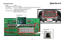
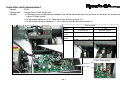
SportsArt TR35 is a piece of fitness equipment that combines advanced technology with a user-friendly design to provide an effective and engaging workout experience. With its intuitive display and a variety of customizable features, the TR35 allows you to track your progress, stay motivated, and achieve your fitness goals.
The TR35 features a variety of pre-programmed workouts designed to target different muscle groups and fitness levels. You can also create your own custom workouts to suit your specific needs. The incline and resistance levels can be easily adjusted to provide a challenging and effective workout.
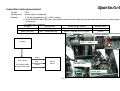


-
 1
1
-
 2
2
-
 3
3
-
 4
4
-
 5
5
-
 6
6
-
 7
7
-
 8
8
-
 9
9
-
 10
10
-
 11
11
-
 12
12
-
 13
13
-
 14
14
-
 15
15
-
 16
16
-
 17
17
-
 18
18
-
 19
19
-
 20
20
-
 21
21
-
 22
22
-
 23
23
-
 24
24
-
 25
25
-
 26
26
-
 27
27
-
 28
28
-
 29
29
-
 30
30
-
 31
31
-
 32
32
-
 33
33
-
 34
34
-
 35
35
-
 36
36
-
 37
37
-
 38
38
-
 39
39
-
 40
40
-
 41
41
-
 42
42
-
 43
43


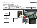
SportsArt TR35 is a piece of fitness equipment that combines advanced technology with a user-friendly design to provide an effective and engaging workout experience. With its intuitive display and a variety of customizable features, the TR35 allows you to track your progress, stay motivated, and achieve your fitness goals.
The TR35 features a variety of pre-programmed workouts designed to target different muscle groups and fitness levels. You can also create your own custom workouts to suit your specific needs. The incline and resistance levels can be easily adjusted to provide a challenging and effective workout.
Ask a question and I''ll find the answer in the document
Finding information in a document is now easier with AI
Related papers
-
SportsArt C531U User manual
-
-
SportsArt Fitness T621 User manual
-
-
-
-
-
-
SportsArt Fitness T631 User manual
-