Fitness Reality 2700 Owner's manual
- Type
- Owner's manual

2700.1-082318
IMPORTANT: Read all instructions carefully before using this product. Retain
this owner’s manual for future reference. The specifications of this product
may vary from this photo, and, are subject to change without notice.
Hyper Extension Bench


SERVICE--------------------------------------------------------------------
2
LABEL PLACEMENT-----------------------------------------------------
3
PRODUCT SAFETY------------------------------------------------------
4
ASSEMBLY PREPARATION--------------------------------------------
5
OVERVIEW------------------------------------------------------------------
6
HARDWARE PACK--------------------------------------------------------
7
PART LIST-------------------------------------------------------------------
8
STEP 1-----------------------------------------------------------------------
10
STEP 2-----------------------------------------------------------------------
12
STEP 3-----------------------------------------------------------------------
14
STEP 4-----------------------------------------------------------------------
16
ADJUSTMENTS------------------------------------------------------------
18
WARRANTY-----------------------------------------------------------------
19
PART REQUEST FORM-------------------------------------------------
20
TABLE OF CONTENTS
1

IMPORTANT: FOR NORTH AMERICA ONLY
For damaged or defective product, questions, replacement parts or any other service support, please
contact our customer service department by the below methods:
For The Best Service, please Email:
service@paradigmhw.com
Response Time: 1-2 Business Days
Emailing us with the information above will be the best method to receive a response during peak business
hours
Website:
www.paradigmhw.com
Toll-Free:
1-844-641-7920
(8:00 AM - 5:00 PM Pacific Standard Time, Monday thru Friday)
Response time may vary via calling
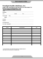
Please have the following information ready when requesting for service:
Your name
Phone number
Model number
Serial number
Part number
Proof of Purchase
For damaged or defective product please contact our customer service before returning to the store.
Paradigm Health & Wellness, Inc.
1189 Jellick Ave.
City of Industry, CA 91748, USA
SERVICE
2

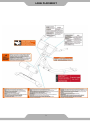
LABEL PLACEMENT
3

WARNING: Before using this equipment you should consult with your personal physician to
see if Hyper Extension Bench is appropriate for you. Do not use this equipment without
your physician’s approval. Do not use this equipment if you have any of the following
conditions or ailments:
Extreme obesity
Glaucoma, retinal detachment or conjunctivitis
Pregnancy
Spinal injury, Cerebral Sclerosis, or acutely swollen joints
Middle ear infection
High blood pressure, hypertension, recent stroke or transient ischemic attack
Heart or circulatory disorders for which you are being treated
A hiatus hernia or a ventral hernia
Bone weaknesses including osteoporosis, unhealed fractures, modularly pins, or surgically
implanted orthopedic supports
Use of anticoagulants including Aspirin in high doses
The Maximum Weight Capacity for this product is 400lbs/181kgs.
Read all instructions carefully before assembling or operating this product. Retain this
owner’s manual, do not remove any safety labels from the machine and keep the original
purchase receipt for future reference.
This bench was designed and built for optimum safety. However, certain precautions apply
whenever you operate this exercise equipment. Be sure to read the entire manual before
assembling and operating this equipment. Also, please note the following safety instructions:
1. Consult your physician or other health care professionals before using the Hyper Extension
Bench.
2. Always wear proper exercise apparel when using this equipment. Use care when getting on or
off the unit.
3. If anytime you feel faint, light-headed, or dizziness while operating the equipment, stop
exercising immediately and contact your physician. You should also stop exercising if you
are experiencing pain or any kind of discomfort.
4. Keep children and pets away from this equipment at all times.
5. Only one person should use this equipment at a time.
6. Make sure your equipment is correctly assembled before you use it. Be sure all screws, nuts,
and bolts are tightened prior to use.
7. Do not operate this or any exercise equipment if it is damaged.
8. Wait 2 hours after eating before using this exercise equipment. If you get nauseous, stop
exercising as soon as you feel queasy.
9. Always use this equipment on a clear and level surface. Do not use outdoors or near water.
10. Keep hands and feet away from any moving parts. Do not insert any object into any
openings.
11. Keep loose clothes, jewelry, limbs and long hair away from moving parts.
12. Children under the age of 12 should not use this fitness equipment.
WARNING: CANCER AND REPRODUCTIV HARM--WWW.P65WARNINGS.CA.GOV
PRODUCT SAFETY
4

Warning: It is highly recommended that you have assistance during the assembly of this
strength equipment.
1. Tools for assembly:
General tools needed for the assembly of this strength equipment:
Metric Allen Key Set
Metric Wrench Set and Adjustable Wrench
Flat Screwdrivers
Phillips Screwdrivers
Rubber Mallet
Silicone Spray Oil
2. Insert the bolts into the frame as illustrated in the drawing of each of the steps.
3. Hand-tighten the bolts, nuts, and screw during assembly. Hand-tightening will allow for easily
aligning the parts during assembly. Tighten all the hardware once the entire unit has been
completely assembled.
4. It is highly recommended that a professional installer assembles the strength equipment. But,
with the proper assistance, the right tools, and strictly following the assembly steps, and given
enough time; the assembly of the unit can be achieved without professional help.
5. Thoroughly read each step before proceeding to assemble the items of that step.
6. To aid in assembly of the equipment, the hardware (bolts, nuts, washer…etc.) has been
presorted according to their corresponding steps. Each bag of hardware is labeled with its
corresponding step number.
7. When the equipment is fully assembled check all the functions for correct operation. Consult the
manual if you experience any issues, or for further help please contact our service department.
See page 2.
5
ASSEMBLY PREPARATION

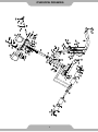
OVERVIEW DRAWING
6

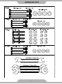
HARDWARE PACK
7

Part#
Description
Qty.
Part#
Description
Qty.
A
Adjustable Post
1
75
Nylon Nut M10*1.5*10T
4
B
Rear Stabilizer
1
76
Nylon Nut
M12*1.75*12T
2
C
Leg
1
158
Hollow Cap
55*55*44*44*36.5L
1
D
Front Stabilizer
1
222
Foam D23*D100*200
2
E
Leg Holder
1
223
Sleeve 155*240
2
F
Pad 200*200*115*50T
2
301
Allen Screw M3*0.5*4L
12
3
Hex Bolt M8*1.25*25L
8
302
End Cap D32*D26*24
4
5
Hex Bolt M10*1.5*75L
4
304
Fixing Ring
D32*D26*13
2
8
Hex Bolt M12*1.75*105L
2
309
Knob D50*47.7*M16
1
50
Flat Washer D18*D8.5*1.2T
8
316
Baffle Plate
D60*D26.5*3T
2
51
Flat Washer D20*D11*2T
8
334
Dip Foam
D24*3T*130L
2
52
Flat Washer
D24*D13.5*2.5T
4
341
Buffer 110*83*5T
4
54
Spring Washer
D15.4*D8.2*2T
8
PART LIST
8

This page was intentionally left blank
9

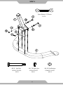
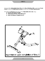
1A. Attach the Leg (C) onto the Front Stabilizer (D). Fasten the Leg (C) to the
Front Stabilizer (D) using:
2 - (8) Hex Bolt M12x1.75x105L
4 - (52) Flat Washer D24xD13.5x2.5T
2 - (76) Nylon Nut M12x1.75x12T
STEP 1
10

STEP 1
11
NO.8 Hex Bolt
M12x1.75x105L
2PCS
NO. 76 Nylon Nut
M12x1.75x12T
2PCS
NO.52 Flat Washer
D24xD13.5x2.5T
4PCS
Open Wrench 17,19mm
2 PCS

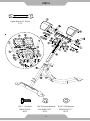
2A. Insert Leg (C) into the bracket of Rear Stabilizer (B) by aligning the two holes
and fasten together using:
2 - (5) Hex Bolt M10x1.5x75L
4 - (51) Flat Washer D20xD11x2T
2 - (75) Nylon Nut M10x1.5x10T
STEP 2
12

STEP 2
13
NO.5 Hex Bolt
M10x1.5x75L
2PCS
NO. 75 Nylon Nut
M10*1.5*10T
2PCS
NO.51 Flat Washer
D20*D11*2T
4PCS
Open Wrench 17,19mm
2 PCS

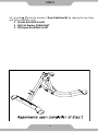
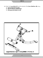
3A. Insert the Adjustable Post (A) into the Rear Stabilizer (B). Loosen the Knob
(309) to allow the Adjustable Post (A) to slide into the Rear Stabilizer (B).
3B. Align the Pad (F) to the hole on the Adjustable Post (A) using:
8 - (3) Hex Bolt M8x1.25x25L
8 - (54) Spring Washer D15.4xD8.2x2T
8 - (50) Flat Washer D18xD8.5x1.2T
STEP 3
14

15
STEP 3
Open Wrench 13,15mm
1 PC
NO.3 Hex Bolt
M8x1.25x25L
8PCS
NO.54 Spring Washer
D15.4xD8.2x2T
8PCS
NO.50 Flat Washer
D18xD8.5x1.2T
8PCS

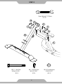
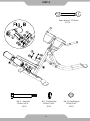
4A. Attach the Leg Holder (E) onto the bracket of the Rear Stabilizer (B) using:
2 - (5) Hex Bolt M10x1.5x75L
4 - (51) Flat Washer D20xD11x2T
2 - (75) Nylon Nut M10x1.5x10T
16
STEP 4

STEP 4
18
17
NO.5 Hex Bolt
M10x1.5x75L
2PCS
NO. 75 Nylon Nut
M10x1.5x10T
2PCS
NO.51 Flat Washer
D20xD11x2T
2PCS
Open Wrench 17,19mm
2 PCS

Pull the Knob (309) and adjust the Hand Grip (A) to the suitable position.
Do NOT hold the chrome shaft of the Hand Grip (A) when adjusting the user height up
or down.
ADJUSTMENTS
18
Page is loading ...
Page is loading ...
-
 1
1
-
 2
2
-
 3
3
-
 4
4
-
 5
5
-
 6
6
-
 7
7
-
 8
8
-
 9
9
-
 10
10
-
 11
11
-
 12
12
-
 13
13
-
 14
14
-
 15
15
-
 16
16
-
 17
17
-
 18
18
-
 19
19
-
 20
20
-
 21
21
-
 22
22


Fitness Reality 2700 Owner's manual
- Type
- Owner's manual
Ask a question and I''ll find the answer in the document
Finding information in a document is now easier with AI
Related papers
-
Fitness Reality 2816 Owner's manual
-
-
Fitness Reality 2812 Owner's manual
-
-
-
-
-
-
-
Other documents
-
Alpulon ZMWV197 User manual
-
ROOMS TO GO 86925026 Assembly Instructions
-
-
-
Home Decorators Collection 5076300200 Installation guide
-
 Cambridge Casual HD-170341T Installation guide
-
 Furniture of America IDF-3371T-7PC Installation guide
-
 Riverside Furniture 39359 Assembly Instructions
-
Kmart 42194965 User manual
-


