Page is loading ...

F.01U.195.915
Rev. 09
JUNE / 2019
BTR-80N, TR-80N, TR-82N
Professional Wireless Intercom System
Operating Instructions

2 BTR-80N, TR-80N, TR-82N
PROPRIETARY NOTICE
The product information and design disclosed herein were origi-
nated by and are the property of Bosch Security Systems, Inc.
Bosch reserves all patent, proprietary design, manufacturing, repro
-
duction, use and sales rights thereto, and to any article disclosed
therein, except to the extent rights are expressly granted to others.
COPYRIGHT NOTICE
Copyright 2019 by Bosch Security Systems, Inc. All rights
reserved. Reproduction, in whole or in part, without prior written
permission from Bosch is prohibited.
*All other trademarks are property of their respective owners.
WARRANTY AND SERVICE INFORMATION
For warranty and service information, refer to the appropriate web
site below:
RTS Intercoms .............................. www.rtsintercoms.com/warranty
RTS Digital
RTSTW
AudioCom
RadioCom
Intercom Headsets
CUSTOMER SUPPORT
Technical questions should be directed to:
Customer Service Department
Bosch Security Systems, Inc.
www.telex.com
TECHNICAL QUESTIONS EMEA
Bosch Security Systems Technical Support EMEA
http://www.rtsintercoms.com/contact_main.php
DISCLAIMER
The manufacturer of the equipment described herein makes
no expressed or implied warranty with respect to anything
contained in this manual and shall not be held liable for any
implied warranties of fitness for a particular application or
for any indirect, special, or consequential damages. The
information contained herein is subject to change without
prior notice and shall not be construed as an expressed or
implied commitment on the part of the manufacturer.
THE LIGHTNING
FLASH AND
ARROWHEAD
WITHIN THE
TRIANGLE IS A
WARNING SIGN
ALERTING YOU OF
“DANGEROUS
VOLTAGE” INSIDE
THE PRODUCT.
CAUTION: TO REDUCE
THE RISK OF ELECTRIC
SHOCK, DO NOT REMOVE
COVER. NO USER-
SERVICABLE PARTS
INSIDE. REFER
SERVICING TO
QUALIFIED SERVICE
PERSONNEL.
THE
EXCLAMATION
POINT WITHIN
THE TRIANGLE
IS A WARNING
SIGN
ALERTING YOU
OF IMPORTANT
INSTRUCTIONS
ACCOMPANYI
NG THE
PRODUCT.
MARKING DEFINTION IF ON PRODUCT.
WARNING: APPARATUS SHALL NOT BE EXPOSED TO DRIPPING OR
SPLASHING AND NO OBJECTS FILLED WITH LIQUIDS, SUCH AS
VASES, SHALL BE PLACED ON THE APPARATUS.
WARNING: THE MAIN POWER PLUG MUST REMAIN READILY OPER-
ABLE.
CAUTION: TO REDUCE THE RISK OF ELECTRIC SHOCK, GROUND-
ING OF THE CENTER PIN OF THIS PLUG MUST BE MAINTAINED.
WARNING: TO REDUCE THE RISK OF FIRE OR ELECTRIC SHOCK, DO
NOT EXPOSE THIS APPRATUS TO RAIN OR MOISTURE.
WARNING: TO PREVENT INJURY, THIS APPARATUS MUST BE
SECURELY ATTACHED TO THE FLOOR/WALL/RACK IN ACCOR-
DANCE WITH THE INSTALLATION INSTRUCTIONS.
This product is AC
or DC powered.

BTR-80N, TR-80N, TR-82N 3
Important Safety Instructions
1. Read these instructions.
2. Keep these instructions.
3. Heed all warnings.
4. Follow all instructions.
5. Do not use this apparatus near water.
6. Clean only with dry cloth.
7. Do not block any ventilation openings. Install in accordance with the
manufacturer’s instructions.
8. Do not install near any heat sources such as radiators, heat registers, stoves,
or other apparatus (including amplifiers) that produce heat.
9. Do not defeat the safety purpose of the polarized or grounding-type plug. A
polarized plug has two blades with one wider than the other. A grounding
type plug has two blades and a third grounding prong. The wide blade or the
third prong are provided for your safety. If the provided plug does not fit
into your outlet, consult an electrician for replacement of the obsolete outlet.
10. Protect the power cord from being walked on or pinched particularly at
plugs, convenience receptacles, and the point where they exit from the
apparatus.
11. Only use attachments/accessories specified by the manufacturer.
12. Use only with the cart, stand, tripod, bracket, or table specified by the
manufacturer, or sold with the apparatus. When a cart is used, use caution
when moving the cart/apparatus combination to avoid injury from tip-over.
13. Unplug this apparatus during lightning storms or when unused for long
periods of time.
14. Refer all servicing to qualified service personnel. Servicing is required if the
apparatus is damaged in any way, such as: the power supply cord or plug is
damaged, liquid is spilled or objects fall into the apparatus, the apparatus is
exposed to rain or moisture, the apparatus is dropped, or the apparatus does
not operate normally.

4 BTR-80N, TR-80N, TR-82N

Table of Contents
Important Safety Instructions .................................... 3
INTRODUCTION .............................................9
General Description .............................................. 9
System Features .................................................... 9
Controls and Connections ................................... 10
BTR-80N – Front Panel ..........................................10
BTR-80N – Rear Panel ...........................................11
Specifications .......................................................... 12
TR-80N - Top Panel ................................................ 14
Specifications .......................................................... 16
TR-82N – Top Panel ............................................... 18
Specifications .......................................................... 20
INSTALLATION ............................................19
Unpacking ........................................................... 19
Antenna Connection ........................................... 20
Antenna Polarization ...........................................20
Distance between Antennas ................................ 21
Antenna Placement ............................................. 21
Improving Reception and Increasing Range ....... 23
OPERATION ..................................................25
BTR-80N ............................................................ 25
Operation ................................................................. 25
Basic Operational Description ................................ 25
System Quick Start .................................................. 25
Transmit and Receive Antennas .............................. 26
2-Wire Intercom Ports ............................................. 26
4-Wire Intercom Ports ............................................. 28
Auxiliary Input/Output ............................................ 28
Base Station Link .................................................... 29
Stage Announce (SA)/Relay ................................... 29
Base Station Link Jack ............................................ 30
Program Jack ........................................................... 30
Powering the Base Station ....................................... 31
Start Up Screen ........................................................ 31
Status Screen ........................................................... 31
RSSI Screen ............................................................. 32
Group/Channel Select Screen .................................. 32
Group/Channel Screen ......................................... 32
Group/Frequency Screen ...................................... 32
Frequency Edit (User-Defined Groups Only) ...... 33
Base Main Settings .................................................. 33
TALK Button ....................................................... 33
Channel Select Button ..........................................33
Local Headset Volume and Gain ......................... 34
Base Transmitter Power ....................................... 34
Squelch Settings ................................................... 34
Stage Announce Level ......................................... 35
Antenna Power ..................................................... 35
CAN Bus Number ................................................36
Intercom Settings ..................................................36
2-Wire Intercom ...................................................37
4-Wire Intercom ...................................................37
Auxiliary Settings .................................................38
ClearScan .............................................................38
Lockout .................................................................39
Copy .....................................................................39
1st Use Defaults ....................................................39
Factory Default .....................................................39
Connection of Multiple Base Stations with the Link
Cables ......................................................................40
Over-the-Air Data Links .........................................41
Master and Servant Base Stations ...........................43
CAN bus ..................................................................43
Base Station Link Configurations ........................45
Wireless Talk-Around Audio Only .........................46
Link Overview ......................................................46
Setup .....................................................................47
WTA and a SINGLE CAN Bus Network ................47
Link Overview ......................................................47
Setup .....................................................................48
WTA and Several CAN Bus Networks ...................49
Link Overview ......................................................49
Setup .....................................................................49
TR-80N/82N ........................................................52
Basic Operational Description .................................52
System Quick Start ..................................................52
Battery Installation ..................................................53
Headset Connection .................................................54
Sidetone ...................................................................54
Antenna Connection ................................................54
On/Off and Volume Control ....................................55
TALK Button ...........................................................55
Audio Channel Select Button ..................................55
Stage Announce (SA) ..............................................56
Wireless Talk Around (WTA) .................................56
Groups and Channels ...............................................57
Transmit Frequency .................................................57
Receive Frequency ..................................................58
Microphone Gain .....................................................58
Battery Display ........................................................58
Low Battery Alert Tone ...........................................59
Transmit Power ........................................................59
Changing the Transmit Power Setting .....................59
Squelch Screen ........................................................60
Transmit Mode Screen .............................................60
LEDs Off/On ...........................................................60
Software Version/Band ............................................61
ClearScan™ .............................................................61
Lock Out ..................................................................61
First Use Default ......................................................61
Factory Reset ...........................................................61

6 BTR-80N, TR-80N, TR-82N
RF Monitor Screen .................................................. 62
Setting Beltpack ID ................................................. 62
On/Off and Volume Control ................................... 63
TALK Button .......................................................... 63
Stage Announce (SA) ............................................. 63
Wireless Talk-Around (WTA) ................................ 64
Groups and Channels .............................................. 65
Transmit Frequency ................................................ 65
Receive Frequency .................................................. 66
Microphone Gain .................................................... 66
Battery Display ....................................................... 66
Low Battery Alert Tone .......................................... 67
Transmit Power ....................................................... 67
Squelch Screen ........................................................ 68
Headphone Options: ................................................ 68
Auxiliary Input: ....................................................... 68
Transmit Mode Screen ............................................ 68
LEDs Off/On ........................................................... 69
Software Version/Band ........................................... 69
ClearScan™ ............................................................ 69
Lock Out ................................................................. 69
First Use Default ..................................................... 69
Factory Reset .......................................................... 70
RF Monitor Screen .................................................. 70
Setting Beltpack ID ................................................. 70
ADDITIONAL RESOURCES ........................ 71
BTR-80N Menu Structure ....................................... 72
TR-80N Beltpack Screen Flowchart ....................... 73
TR-82N Beltpack Screen Flowchart ....................... 74
Frequency Bands ................................................. 75
North America ..................................................... 75
Europe .................................................................. 75
Band Pairing for Systems ........................................ 75
Frequency Plan ........................................................ 76
Troubleshooting .................................................. 77
Battery Information ............................................. 78
Battery Warnings .................................................... 78
Battery Life ............................................................. 78
Cold Temperatures and Batteries ............................ 78
2-Wire Systems Specification ............................. 79
Certificate Information .......................................80
Accessories and Replacement Parts .................... 83
Three (3) Band Base Stations ............................. 86
Identifying a Three (3) Band Unit .......................... 86
Regulatory Changes and the Three Band ................ 86
Changing Channel Maps ......................................... 86

CHAPTER 1
Introduction
General Description
RTS Wireless BTR-80N UHF Synthesized Wireless Intercom
system offers reliable, high-performance, high-fidelity full-
duplex communications delivered with minimum spectrum
usage.
The BTN-80N system includes the BTR-80N frequency agile
base station and up to four (4) TR-80N or TR-82N frequency
agile beltpacks operating in full-duplex communications. An
almost unlimited number of beltpacks may be used with a base
station if the beltpacks are in Push-To TX mode (half- duplex).
The BTR-80N system incorporates two (2) audio channel
operation, permitting the beltpack operator to choose between
two (2) separate audio channels of communication, with the
base station tracking the beltpack selection. This allows the user
the flexibility to create a party line and a private line within the
same beltpack.
The BTR-80N system is perfectly suited for standalone
operation and can also interface with other RTS wired intercom
systems. In addition to the external intercom systems interfaces,
the system provides connections for auxiliary balanced audio
input and output, as well as wireless talk-around (WTA) and
stage announce (SA) features.
The BTR-80N system has been designed for reliable, efficient
operation. Operating in the 482 to 722MHz range, the units
perform reliably at line-of-sight distances of 1000 feet. With
available antenna systems from RTS, the effective operating
range can be extended. The high-efficiency beltpacks provide
between 8 and 11 hours of uninterrupted operation using NiMH
rechargeable battery packs.
System Features
• Frequency-agile base station and beltpacks. No external
computer/device required to select frequencies.
• Backlit base-station LCD allows the user to easily monitor
the beltpack’s status and change base station frequencies.
• Squelch adjust on the BTR-80N, TR-80N, and TR-82N
beltpacks.
• Beltpack’s battery level displayed on the base station and in
beltpack’s menus.
• ClearScan function on base station and beltpack to
automatically find the best channels on which to operate.
• Full-duplex (simultaneous talk and listen) or Push-to-Tx
(half duplex) operation.
• Compatible with Audiocom (Telex), RTS TW and Clear-
Com wired intercoms.
• Two (2) independent channels of intercom audio with the
ability to operate party line and RTS matrix on the same
intercom channel at the same time.
• WTA (Wireless Talk-Around) beltpack control. This feature
allows beltpacks to talk to each other, but their audio is lifted
from any wired system connected to the base station.
• SA (Stage Announce) beltpack control. Allows the user to
direct their audio to a jack on the back of the base for P.A.
systems or other external audio systems.
• Relay contact closure on the base when the SA button is
pressed.
• TR-82N features two (2) audio channel binaural operation in
either stereo or mono mode.
• TR-82N has a 1/8-inch (3.5mm) jack for auxiliary input
from another audio source, such as an IFB, iPod, or other
similar device.
• Beltpack units contained in a weather and shock resistant die
cast magnesium case.
• Convenient IEC power connector on the base station so the
unit can plug directly to outlets. No in-line or wall plug
power supply.
• Dark mode configurable on TR-80N and TR-82N beltpacks.
This shuts down all LEDs.

10 Introduction BTR-80N, TR-80N, TR-82N
Controls and Connections
BTR-80N – Front Panel
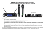
FIGURE 1. BTR-80N - Front Panel
1. Power Switch - Do not power up a base station within three
(3) seconds of the unit being turned off. Voltages within the
unit need to drop below a threshold before being repowered.
If powered-up in less than three (3) seconds, the unit may
boot as the wrong frequency band. Even with the unit
powered down via the power switch, some circuits within
the base remain energized. To completely remove power to
the unit, disconnect the power cord.
2. [MENU] and [SET] buttons - Use to select menus and set
options on the LCD.
3. Backlit Graphics LCD (Liquid Crystal Display)
4. [UP] and [DOWN] buttons - Use to select base station
options on the LCD.
5. Portable Station Connect - Use buttons to enable or
disable the respective receiver’s audio. GREEN LED -
Audio enabled, LED OFF - Audio disabled.
6. 4-wire Selection/Peak Input Indicators - Displays when
4-wire intercoms are active with green indication. A red
indication means the intercom input level is too high.
7. 2-wire Selection/Peak Input Indicators - Displays which
2-wire intercoms are active with a green indication. A red
indication means the intercom input level is too high.
8. Auxiliary Selection/Peak Input Indicator - Displays if
auxiliary input is on with a green indicator. A red indicator
means the intercom input level is too high.
9. Headset Intercom Select - Controls the intercom to which
the local headset is connected. Each press of the button
changes the connection to channel 1, channel 2, or both.
10. Talk/Peak Light - LED is green when talk button #11 is
active. A normal mic gain setting causes the LED to flash
red on the loudest speech levels. If the gain is too high, the
LED is red at normal speech volumes.
11. Talk Butt on - Press to enable the audio path from the local
handset. LED #10 turns green when enabled. A quick press
and release latches button on. If the talk function is latched
on, pressing the talk button again turns it off.
12. Local Headset Connector - Male XLR connector or
female XLR connector. A dynamic electret headset
microphone is automatically detected. Microphone gain and
volume are configured in the software menus.
FIGURE 2. Local Headset Wiring

BTR-80N, TR-80N, TR-82N Introduction 11
BTR-80N – Rear Panel
FIGURE 3. BTR-80N - Rear Panel
1. Receive Antenna - Female “TNC” Connector. Color band
on antenna must match color dot on base station.
2. Relay Contact - A dry contact closure which activates
when a beltpack user presses the stage announce (SA)
button. Normally Open (NO). The rating is one amp at 24V
maximum.
3. Program Connector - Used to update software in unit.
4. Base Station Link Jacks - When multiple base stations are
connected through this jack, it allows wireless talk around
(WTA) audio from the beltpacks to be routed from system
to system. Also allows CAN bus data to be passed between
base stations.
5. Intercom 1 - Interface to wired intercom channel 1.
2-Wire
- Male and female 3-pin XLR connectors wired
in parallel. The connectors are switched to the
appropriate intercom configuration via software.
4-Wire - An
RJ-11 type jack compatible with Matrix
type intercom systems.
6. Intercom 2 - Interface to wired intercom channel 2.
2-Wire
- Male and female 3-pin XLR connectors wired
in parallel. The connectors are switched to the
appropriate intercom configuration via software.
4-Wire - An
RJ-11 type jack compatible with Matrix
type intercom systems.
7. Auxiliary Input/Output - One 3-pin female XLR / 1/4-
inch combination input connector and one 3-pin male XLR
output connector.
8. Stage Announce Output - Passes the audio from any of the
base station’s beltpacks that have selected Stage Announce
(SA).
9. DC Input Jack - Accepts 12-15 VDC (5.5mm by 2.5mm
screw on plug), 3.5 Amps to power the base station from a
DC source. Base may be connected to DC and AC source at
the same time. If AC source fails the base automatically
switches to DC power. Inside the base there is a user
replaceable fuse in-line with the DC input jack. This fuse is
a 5A, 250V, 5x20mm, fast acting ceramic cartridge.
10. Power - IEC receptacle. Accepts 100–240 VAC, 1A
maximum, 50–60Hz.
11. Transmit Antenna - Female TNC Connector. Color band
on antenna must match color dot on base station.

12 Introduction BTR-80N, TR-80N, TR-82N
Specifications
Overall
RF Frequency
TX Range
482 - 608 MHz in 18 MHz TX bands
RX Range
US/Canada
572 - 608 MHz in 18 MHz RX bands
653 - 663 MHz for 3 band
Rest of the World
572 - 608, 614 - 722 MHz in 18 MHz RX bands
Power Requirements
100 - 240 VAC, 50 - 60 Hz 1 Amp Max,, IEC receptacle
DC Only
12 - 15 VDC, 3.5 Amps
Temperature Range
-4° F to 130° F (-20° C to 55° C)
Dimensions
19.00” W x 1.72” H x 14.00” D (48.3cm x 4.4cm x 35.6cm)
Weight
7lbs 2oz (3.24kg)
TX Antenna
1/2 Wave (supplied), TNC Male Connector
RX Antenna
1/2 Wave (supplied), TNC Male Connector
FCC ID
B5DM528
Frequency Response
200Hz–4kHz
Four Wire Input
Level Adjustable (2Vrms typical)
Two Wire Input
Level Adjustable (2Vrms typical)
Telex Intercom
Input/Output Level Adjustable (1Vrms typical), Line Impedance 300Ω
RTS Intercom
Input/Output Level Adjustable (0.775Vrms typical), Line Impedance 200Ω
Clear-Com
Input/Output Level Adjustable (1Vrms typical), Line Impedance 200Ω
Auxiliary Input
Adjustable (2Vrms typical)
Auxiliary Output
Adjustable (2Vrms typical into 600Ω)
Stage Announce Output
Internally Adjustable (2Vrms typical at rated deviation into 600Ω)

BTR-80N, TR-80N, TR-82N Introduction 13
Stage Announce Relay
Dry contact, rated at 1 Amp, 24V Max
Microphone Input Sensitivity
9mV
Local Headset Output
40mW output into 600Ω (1% Distortion)
Transmitter
Type
Two Synthesized Transmitters
Transmit Power (each transmitter)
Selectable: off, 10mW, 50mW, 100mW, 249mW
Modulation Type
FM
Deviation
4kHz
RF Frequency Stability
2.5PPM
Modulation Limiter
Peak-Responding Compressor
Radiated Harmonics & Spurious
Exceeds FCC specifications
Receiver
Type
Triple Conversion Superheterodyne, four Independent IFs, FM
RF Sensitivity
<0.6V for 12dB SINAD
Squelch Threshold
adjustable - 12/20/24dB SINAD
IF Selectivity
6dB at 30kHz bandwidth
Image Rejection
70dB or better
Squelch Quieting
90 dB
RF Frequency Stability
2.5 PPM

14 Introduction BTR-80N, TR-80N, TR-82N
TR-80N - Top Panel
FIGURE 4. TR-80N Top Panel
1. On/Off Volume Control - Turns the beltpack power on.
2. Wireless Talk-Around (WTA) - When pressed, the user’s
audio disconnects from the wired intercom, auxiliary input/
output and the base station’s local headset. Other beltpack
users on the audio channel can hear the user as normal. The
button activates the nearby red LED and the TALK button.
3. Stage Announce (SA) - When pressed, the user’s audio
routes to the stage announce connector on the back of the
base station. The user also loses their sidetone, indicating
that stage announce is active. The other wireless beltpacks
and wired users do not hear the user’s audio. The button is
non-latching and activates the nearby red LED and TALK
button.
4. Audio Channel Select Button - Allows user to select
either audio channel 1 or audio channel 2.
5. Bat/Peak Light (BAT/PK) Light flashes once when unit
turns on if the battery is good. If the light stays on, the
battery is low. If the light does not flash, the battery is dead.
A normal microphone gain setting causes the LED to flash
for some of the words at normal speech levels. If the gain is
too high, the LED displays a continuous red during all
words at normal speech levels.
6. Talk Light - LED is on when the talk button, SA, or WTA
is active.
7. Talk Butt on - Press to enable the audio path from the local
headset microphone. The “TALK” LED, #6, turns red when
enabled. A quick press and release latches the talk function,
unless latching has been disabled. Holding the button for
over a half-second causes the audio path to be enabled only
for as long as the button is held. If the talk function is
latched on, pressing the talk button again turns it off.

BTR-80N, TR-80N, TR-82N Introduction 15
.
FIGURE 5. TR-80N Rear Panel/Connector/Antennas
1. MENU and SET buttons- Use to select menus and set
options on the LCD.
2. LCD (Liquid Crystal Display)
3. UP and DOWN buttons - Use to select beltpack options
on the LCD.
4. Programming Connector - Use to update software in unit.
5. Headset Connector - Male XLR or female XLR connector.
A dynamic or electret headset microphone is automatically
detected by the beltpack and a bias voltage supplied, if
needed.
6. Battery Latch - Press down to release the battery pack.
While holding the latch down, slide the battery pack about
1/8 inch back toward the latch until it stops, then lift it out.
7. Receive Antenna - Screw type 1/4-wave replaceable
antenna. The color dot on the screw end of the antenna must
match color dot on the antenna receptacle.
8. Transmit Antenna - Screw type 1/4-wave replaceable
antenna. Color dot on the screw end of the antenna must
match color dot on antenna receptacle.
FIGURE 6. Headset Jack Wiring
IMPORTANT: Microphone gain and transmit mode is
set via software menus.

16 Introduction BTR-80N, TR-80N, TR-82N
Specifications
Overall
RF Frequency
TX Range
US/Canada
572 - 608 MHz in 18 MHz TX bands
653 - 663 MHz for 3 band
Rest of the World
572 - 608, 614 - 722 MHz in 18 MHz TX bands
RX Range
482 - 608 MHz in 18 MHz RX bands
Power Requirements
6 “AA” Cells Alkaline (NiHM Optional)
Current Draw
200mA (Push-To-Talk, Talk On)
Temperature Range
-4°F to 130°F (-20°C to 55°C)
Dimensions
3.75” W x 5.05” H x 1.65” D (9.5cm x 12.8cm x 4.2cm)
Weight
16oz (454g)with alkaline batteries
TX Antenna
1/4 Wave (supplied), Screw Type, Replaceable
RX Antenna
1/4 Wave (supplied), Screw Type, Replaceable
FCC ID
B5DM530
B5DM538
Frequency Response
200Hz–4kHz
Microphone input sensitivity
7mV
Local Headset Output
40mW output into 600Ω (1% Distortion)
Transmitter
Type
Synthesized
Transmit Power
Selectable: auto, 5, 50, and 100mW
US 3 Band:, Selectable: auto, 5, 20 mW
Modulation Type
FM
Deviation
4kHz

BTR-80N, TR-80N, TR-82N Introduction 17
RF Frequency Stability
2.5PPM
Modulation Limiter
Peak-Responding Compressor
Radiated Harmonics &Spurious
Exceeds FCC specifications
Receiver
Type
Triple Conversion Superheterodyne, Synthesized FM
RF Sensitivity
<0.6V for 12dB SINAD
Squelch Threshold
adjustable - 12/20/24dB SINAD (about 1.0 μV)
IF Selectivity
6dB at 30kHz bandwidth
Image Rejection
70dB or better
Squelch Quieting
90dB
RF Frequency Stability
2.5 PPM

18 Introduction BTR-80N, TR-80N, TR-82N
TR-82N – Top Panel
FIGURE 7. TR-82N Top Panel
1. On/Off and Volume Control - Turns beltpack power on
and controls headset volume for intercom channels “1” and
“2”. Either knob, “1” or “2”, turns the beltpack on. Both
knobs must be off to turn the beltpack off. If only one knob
is on, the intercom channel “1” or “2” is on for both
transmit and receive.
2. Wireless Talk-Around (WTA) - When pressed, the user’s
audio disconnects from the wired intercom, auxiliary input/
output, and the base station’s local headset. Other beltpack
users on that audio channel can hear the user as normal. The
software can select which intercom channel(s)—1, 2, 1+2,
or the currently selected channel—is activated with the
WTA button. The WTA button activates the nearby red
LED as well as the software-selected intercom channels
TALK LED if not already active.
3. Stage Announce (SA) - When pressed, the user’s audio
routes to the stage announce connector on the back of the
base station. The user also loses their sidetone, indicating
stage announce is active. The other wireless beltpacks and
wired users do not hear the user’s audio. The button is non-
latching and activates the nearby red LED and TALK
button.
4. Talk Butto n - Press to enable the audio path to intercom
channels 1, 2, or 1+2, from the local headset microphone.
The associated TALK LED #6 turns red when enabled. A
quick press and release latches the talk function, unless
latching has been disabled., Holding the button for over 1/2
second causes the audio path to be enabled only for as long
as the button is held. If the talk function is latched on,
pressing the talk button again and it turns off.
5. Low Battery/Peak (BAT/PK) Light - Light flashes once
when unit is turned on if the battery is good. If the light
stays on, the battery is low. If the light does not flash, the
battery is dead. A normal microphone gain setting causes
the LED to flash for some words at normal speech levels. If
the gain is too high, the LED displays red during all words
at normal speech levels.
6. Talk Light - Turns red when enabled by associated TALK
or WTA button.

BTR-80N, TR-80N, TR-82N Introduction 19
1. MENU and SET buttons - Used to select menus and set
options on the LCD.
2. LCD (Liquid Crystal Display)
3. UP and DOWN buttons - Used to select beltpack options
on the LCD.
4. Programming Connector - Used to update software in
unit.
5. Auxiliary Input Audio Jack - 1/85” (3.5mm) mono input
jack. Local only to beltpack.
6. Headset Connector - Male XLR connector or female
XLR. A dynamic or electret headset microphone is
automatically detected by the beltpack and a bias voltage
supplied, if needed. 4-pin Telex/RTS units are monaural. 5-
pin Telex/RTS units have a software setup to select if XLR
pin 3 or 5 is the channel 2 output and if pin 3 is ground.
7. Battery Latch - Press down to release the battery pack.
While the latch is held down, slide the battery pack about 1/
8 inch back, toward the latch, until it stops, then lift it out.
8. Receive Antenna - Screw type 1/4-wave replaceable
antenna. The color dot on the screw end of the antenna must
match color dot on the antenna receptacle.
9. Transmit Antenna - Screw type 1/4-wave replaceable
antenna. The color dot on the screw end of the antenna must
match color dot on the antenna receptacle.
IMPORTANT: Microphone gain and transmit mode is
set via software menus.
FIGURE 8. TR-82N Rear Panel/ Connector/Antennas
FIGURE 9. Handset Jack Wiring

20 Introduction BTR-80N, TR-80N, TR-82N
Specifications
Overall
RF Frequency
TX Range
US/Canada
572 - 608 MHz in 18 MHz TX bands
653 - 663 MHz for 3 band
Rest of the World
572 - 608, 614 - 722 MHz in 18 MHz TX bands
RX Range
482 - 608 MHz in 18 MHz RX bands
Power Requirements
6 “AA” Cells Alkaline (NiHM Optional)
Temperature Range
-4° F to 130° F (-20° C to 55° C)
Dimensions
3.75” W x 5.35” H x 2.02” D (9.5cm x 13.5cm x 5.1cm)
Weight
21 oz (595 g) with alkaline batteries
TX Antenna
1/4 Wave (supplied), Screw Type, Replaceable
RX Antenna
1/4 Wave (supplied), Screw Type, Replaceable
FCC ID
B5DM531
B5DM539
Frequency Response
200 Hz–4 kHz
Microphone input sensitivity
7 mV
Local Headset Output
40 mW output into 600 Ω (1% Distortion)
Transmitted
Type
Synthesized
Transmit Power
Selectable: auto, 5, 50, and 100 mW
US 3 Band:, Selectable: auto, 5, 20 mW
Modulation Type
FM
Deviation
4kHz
RF Frequency Stability
2.5 PPM
Modulation Limiter

BTR-80N, TR-80N, TR-82N Introduction 21
Peak-Responding Compressor
Radiated Harmonics &Spurious
Exceeds FCC specifications
Receiver
Type
Two, Triple Conversion Superheterodyne Receivers, Synthesized, FM
RF Sensitivity
<0.6 V for 12 dB SINAD
Squelch Threshold
adjustable - 12/20/24 dB SINAD
IF Selectivity
6 dB at 30 kHz bandwidth
Image Rejection
70 dB or better
Squelch Quieting
90 dB
RF Frequency Stability
2.5 PPM

22 Introduction BTR-80N, TR-80N, TR-82N
/