Designtech AutoCommand 20028 Installation Instructions Manual
- Category
- Remote starters
- Type
- Installation Instructions Manual

Section 5 - Page 17
DesignTech International, Inc.
1-800-DESIGNTECH
www.designtech-intl.com
©1998 All Rights Reserved
DesignTech International, Inc.
DesignTech disclaims any liability or responsibility arising out of any inaccuracies of this information or use of this information in installation or otherwise.
Installation Instructions #20024-28
1
AutoCommand
®
Model 20024/20028
Remote Control Car Starter with Alarm and
Keyless Entry Features Installation Manual
DesignTech International, Inc. • 7955 Cameron Brown Court • Springfield, Virginia 22153 USA • 703-866-2000 or 800-337-4468
Please Read Completely Before Beginning
Congratulations on your purchase of the AutoCommand® Remote Car Starter. The AutoCommand® Remote Car Starter system allows you
to start the car by remote control from the comfort of your home or office in order to cool it down in the summer or heat it up in the winter.
This model includes keyless entry and alarm features.
AutoCommand
®
is for automatic transmission cars only. It is an extremely sophisticated system with multiple built-in safety and security
features.
The AutoCommand
®
Remote Car Starter:
• Will start your car by remote control, and run the heater, defroster, or air conditioner to warm up or cool down the car.
• Is designed to start the car if it is in park, and only if the hood is closed.
• Has Lock, Unlock and Trunk keyless entry features.
• Has alarm functions including starter kill which becomes active when the doors are locked with the remote control.
• Will attempt to start the car for up to six seconds, but no longer (to avoid damage to the starter motor). Should the car not start, or if it stalls
after starting, the AutoCommand® will make two further attempts to start it.
• Will not let the car be driven without the key in the ignition.
• Shuts itself off automatically after 10 or 15 minutes (programmable) if you forget to come out to your car.
• Will shut off if the brake pedal is pushed, the hood is opened, or the transmission is shifted out of park - unless the key is in the ignition and
in the “run” position.
• Allows you to remove the key while leaving the car running with the doors locked for up to 10 or 15 minutes utilizing the QUICK STOPTM
option. (See Separate User Tip Sheet)
• Starts the car automatically whenever the temperature drops below 0oF (-18oC), or if the battery voltage drops below 11 volts with the Cold
StartTM option activated. (See Separate User Tip Sheet)
• Has the “Daily StartTM” feature which allows the vehicle to be started at the same time the following day. (See Separate User Tip Sheet).
• Is quality engineered, microprocessor controlled, and made in the USA to provide many years of reliable use.
• Comes with a 2 year warranty.
V 8.7
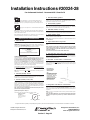
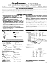
Wiring Diagram
Circuit
Color Function Type
Required
Pink Power (+12V) Input Yes
White Accessory Relay output Yes
Yellow Starter Relay output Yes
Blue Ignition 1 Relay output Yes
Green Ignition 2 Relay output Maybe
Black Ground Input Yes
ON/OFF Switch Jack Coax
Antenna Jack
Power Harness
Color Function Type Required
White/Black Ignition 3 (-)400mA No
Brown/White Alarm Disable (-)400mA No
Brown Accessory (-)400mA No
Blue Horn (-)400mA No
Yellow Lights Relay Output No
Control Harness
Color Function Type Required
Orange Brake (+)Input Yes
Violet Hood (-)Input Yes
Green Tach (-)Input No
Red/White Alarm Input (-)Input No
Red/Black Diesel (+/-) Input No
LED
White-Option Red-Code Learn
Lock/Unlock/
Trunk Harness
Plug-in LED
Shock Sensor Plug
Tools required to install the AutoCommand
®
Unit:
Wire Cutters/Strippers Soldering Iron Pliers
Testmeter Screwdriver Drill
We highly recommend that all connections be soldered for reliability.
AutoCommand®
Receiver Module
Control Harness
(10 position)
Parts Kit in plastic baggy:
Lock/Unlock/Trunk Harness Alcohol Pad 30 A Fuse Plug-in LED
2 Antenna Clips with Adhesive Pads Hood Pin Switch Set 2 Cable Ties
On/Off Control Switch Warning Label Window Decal Ring Terminal
Alchohol
Pad
Transmitter
(Model 20028 has 2 transmitters)
Siren
(Model 20028 only)
Antenna
6 Power &
Ignition wires Shock Sensor
(Model 20028 only)
2 Relays with relay harnesses
(Model 20028 only)
WARNING
This car is equipped with a remote control starting device.
Disable before working on car!
AVERTISSEMENT
Ce véhicule est équipé d’un systéme de démarrage a distance. Mettez-le hors
fonction avant d’eflectuer toute opération d’entretien ou de réparation!
Fax On Demand Section 5 - Document #115 - Sheet 1 of 6

Section 5 - Page 18
DesignTech International, Inc.
1-800-DESIGNTECH
www.designtech-intl.com
©1998 All Rights Reserved
DesignTech International, Inc.
DesignTech disclaims any liability or responsibility arising out of any inaccuracies of this information or use of this information in installation or otherwise.
Installation Instructions #20024-28
2
WARNING!
On cars with airbags, you may notice bright yellow tubes or
harnesses underneath the steering column area. DO NOT tamper with
these wires in any way, to prevent personal injury and/or damage to the air
bag system.
WARNING!
Battery gases are explosive. Do not smoke while working near
the car’s battery.
Note
: Some installers connect a battery charger to the vehicle’s battery dur-
ing installation. This is fine, but it must be removed before running the vehicle
under AutoCommand® control.
When working the wires through the car’s firewall, be sure to protect them
from sharp metal edges and from hot surfaces on the engine.
INSTALLATION INSTRUCTIONS
1. Before You Start
Take the time to read through the whole installation manual.
IMPORTANT: After having read the entire manual, start the installation by
putting the yellow WARNING STICKER in the engine compartment. Choose
a surface that is clean and readily visible when the hood is open.
WARNING
This car is equipped with a remote control starting device.
Disable before working on car!
AVERTISSEMENT
Ce véhicule est équipé d’un systéme de démarrage a distance. Mettez-le hors
fonction avant d’eflectuer toute opération d’entretien ou de réparation!
POWER & IGNITION HARNESS
The AutoCommand® module will be installed under the dash once all wiring
has been completed. Do not mount the module at this time! You will need
to check the diagnostic light (LED) as the installation progresses. Lo-
cate (or drill) a hole in the firewall to run the VIOLET, GREEN, YELLOW, and
BLUE wires of the Control Harness and the PINK wire of the Power harness
through into the engine compartment. The remaining short wires stay in the
passenger area. Leave about a foot of the wire harness under the dash for
ease of working and visual access to the diagnostic light.
The Installation Information section of our web site www.designtech-intl.com
is available 24 hours/day to provide you with up to date vehicle wiring informa-
tion for your particular vehicle if needed.
Note:
Always connect the
Pink
and
Black
wires before connecting any of the
other wires.)
2. Black Wire (16 AWG) - Ground
Connect the BLACK wire to a very good, clean chassis ground in the driver’s
kick panel area. Use the small red ring terminal if needed. The metal bracing
around or beneath the dash board is not adequate.
3. Pink Wire (12 AWG) - Power (+12V)
Connect the ring terminal at the end of the short PINK wire to the +12 volt
terminal of the battery. Run the long pink wire through the firewall of your
vehicle. Join the remaining ends of the power wire together by soldering them.
Alternatively, you may wish to use a yellow butt terminal, but we recommend
soldering. Now insert the 30 amp green fuse into the holder. As the power
wire is connected the LED will blink once.
Note:
Failure to properly install the fuse holder and 30 amp fuse to the
pink wire voids all product warranties.
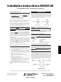
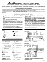
Ignition Key Diagram for Steps 4-7
The vehicle’s wires are found coming off of the key switch.
ACC
ACC
Lock/Off
RUN
START
Ignition Key Diagram
for Steps 4-7
The vehicle’s wires are
found coming off of the
key switch.
4. Blue Wire (14 AWG) - Ignition 1
Connect the BLUE wire to the ignition 1 wire of your vehicle. This wire will
measure +12V on the test meter in the “run” and “start” position, and is off
(ground) in the “lock/off” and “accessory” position.
5. Green (14 AWG) - Ignition 2
Connect the GREEN wire to the second IGN2 wire (if applicable) of your ve-
hicle. This wire will power the heater/air conditioner (in most cars). This wire
will measure +12V on the test meter in the “run” position only.
6. White Wire (14 AWG) - Accessory
Connect the WHITE wire to the accessory wire which is +12V in the “run” and
“accessory” position, but off (ground) in the “start” and “off” positions.
7. Yellow (14 AWG) - Starter
Connect the YELLOW wire to the starter wire. This wire will measure +12V on
the test meter in the “start” position only.
Note
: Nissan vehicles have two starter wires. Connect both starter wires to
the YELLOW wire.
8. Plug-In On/Off Switch -- Plug-In LED
Plug the ON/OFF control switch into the module just to the right of the power
wires.
Note
: Mount the control switch in the dash so that it is easily accessible
and so that the “ON” position is facing upward. Connection of this
switch is mandatory. Plug the LED into the red connector between the 2
push button switches.
Control Harness (All wires are the smaller 18 AWG size)
9. Red / Black Wire Diesel “wait to start” Control Harness
This wire is only used in diesel vehicle applications - and is optional. This
wire can be hooked up to the “wait to start” light’s switched wire behind the
dash. If option 9 is set, this wire will feed information to the AutoCommand as
to when to crank the vehicle over.
10. Violet Wire - Hood Pin Switch - Control Harness
The hood pin switch MUST be installed with the AutoCommand®. It pre-
vents operation of the AutoCommand® when the hood is open and is used to
initialize the unit. Connect the VIOLET wire to the hood pin switch using the
red connector.
How to share a
hood pin switch
with an alarm...
Note:
If you already have a hood pin
switch which is being used by
a car alarm system, you may
share the wiring -- but be sure
to diode isolate each wire
going to the hood pin switch
with the bands of diodes
pointing towards the pin
switch as shown here:
11. Orange Wire - Brake Shut-off - Control Harness
Connect the ORANGE wire to the brake wire which receives +12V when the
brake pedal is depressed. This wire must be connected. It arms a critical
safety feature which disables the AutoCommand® when the brake pedal is
depressed.
Note
: In some cars, the ignition must be in the “on” position to test the power
in the brake wire.
Note:
If the IGN1 & IGN2 wires come on whenever the brake is depressed
and the hood is open this just means you need to initialize the unit in
Step 12.
Fax On Demand Section 5 - Document #115 - Sheet 2 of 6

Section 5 - Page 19
DesignTech International, Inc.
1-800-DESIGNTECH
www.designtech-intl.com
©1998 All Rights Reserved
DesignTech International, Inc.
DesignTech disclaims any liability or responsibility arising out of any inaccuracies of this information or use of this information in installation or otherwise.
Installation Instructions #20024-28
3
12. Initializing the AutoCommand®
BEFORE THE CAR WILL START FOR THE FIRST TIME, YOU MUST INI-
TIALIZE THE AUTOCOMMAND®
A. The AutoCommand® requires the installer to open the hood and then
press and hold the brake pedal. Note: The dash lights will come on if the
unit is not initialized.
B. While depressing the brake (with the engine off and the hood open) turn
the ignition key to the “RUN” (not “start”) position.
C. Put the car in gear from the “PARK” position.
D. Put the car back in “PARK” and release the brake.
Note
: Confirm initialization by turning the ON/OFF control switch “OFF” and
then “ON”. The red LED on the AutoCommand® module will flash once imme-
diately as the switch is flipped from the “OFF” to the “ON” position.
If the unit is not initialized then the dash lights will come on (the AutoCom-
mand® powers up the ignition wires) when the brake is depressed when the
hood is open when the control switch is on. REPEAT STEPS A THROUGH D.
See the purple colored Trouble Shooting Sheet if necessary.
13. Green Wire - Tach Input - Control Harness
The AutoCommand® has two ways of monitoring the car during the starting
process. Both ways will ensure a clean, accurate start. Read about both
methods before deciding which one to use. Normally you should try the “No
TachTM” method first.
“No TachTM” Starting
This starting method does not require the connection of the GREEN tach wire.
This method will start the car by reading the car’s voltage before attempting to
start, and then looking for a voltage increase when the alternator kicks in.
This feature automatically takes into account voltage, temperature, and the
time since the vehicle was last run. The “No-TachTM” starting is preset at the
factory and you can skip step 13A if you would like to use it. Note that if the
vehicle is hard to start, set option #3 (step 23) for “extended crank.”
Tachometer sensing
If the vehicle is generally hard starting (requiring a cranking time of more than
1 second) you will get more accurate starting with the tachometer sensing
starting method. This method starts the car by reading the engine speed
(tach) information from a wire under the hood. If you choose tachometer
sensing, connect the GREEN (18 awg) wire to the car’s tach wire under the
hood (normally the negative side of the coil or tach output of coil pack). After
you have connected the GREEN wire, you need to teach the AutoCommand®
the vehicle’s tach rate at idle. Proceed to step 13A.
Note
: You must have already initialized the module from Step 12.
13A. Tach Rate Learning
Note
: Only use if the tachometer sensing method is chosen.
A. Connect the GREEN wire to the car’s tach wire under the hood.
B. Turn the On/Off control switch to the “OFF” position. Wait 5 seconds for
the first set of LED flashes to stop.
C. Push the White “option” button once and you will see the red LED flash.
Now push the middle button on the transmitter for a second until you see
the red LED flash again. You are now in TACH mode. (If the LED flashed
twice -- simply push the transmitter button again until you get only one
flash).
D. Wait 5 seconds for the red LED to flash 3 times.
E. Turn the On/Off control switch back to the “ON” position
F. Start the car and let it get to a
normal
idle. Do not press on the gas
pedal.
G. Push the red “code” button for a second.
H. Watch the red LED. It will turn on (solidly) after 3 or 4 seconds, indicat-
ing that the idle rate has been learned.
I. Watch the LED stay on steady as the vehicle is running and goes off as
you rev the rpms above twice the idle rate. The LED must go out when
you rev it above twice the idle rate to confirm correct tach learning.
J. Turn the key to the “Lock/Off” position.
K. Turn the On/Off control switch off and the LED will go out.
Note
: Once these steps are complete – you cannot use the LED to confirm
tach again. You can however repeat the above steps to learn tach over again
at any time.
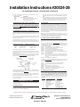
OPTIONAL STEPS
Many of the optional steps require a relay to be hooked up. The most common
relay used for this type application is the Bosch type relay. Use the diagram
below for a typical hookup. If you have another relay then you need to know
that pins 85 and 86 in this diagram relate to the coils of the relay. Pin 30 is the
‘common’, and pin 87 is the ‘normally open’ contact. If your relay has a pin
87A in the middle it is the normally closed contact and is not used. (The dia-
gram below is typical for horn or trunk applications).
14. Yellow Wire - Headlights/Parking Lights - Control
Harness
Connect the YELLOW wire which is optional, if your want to activate the low
beam headlights or parking lights. After the AutoCommand® has started the
car, the lights will remain on until the system shuts off after 10 minutes, or
when the brake pedal is pressed, or when the key is inserted into the ignition
and the car is put into gear. This is a relay +12V output. Connect the YEL-
LOW wire to the wire that powers the lights for this feature.
15. Blue - Horn / Siren - Control Harness
The BLUE wire which is optional, signals the horn to honk (or siren to chirp)
once each time the AutoCommand® starts the car and each time the locks are
locked or unlocked This is a 400 mA transistor ground output which MUST
drive a relay as in the left diagram above. (Included in Model 20028 only). If
you are using the relay and relay harness included with Model 20028, the
connections are as follows.
Harness Wire Connection
Black AutoCommand® Blue wire
White +12V Constant
Blue +12V Constant
Yellow To Siren’s Brown (or colored) wire [Connect the
Black wire from the Siren to Ground]
16. Brown Wire - Accessory Pulse - Control Harness
The BROWN wire which is optional, is the Accessory Pulse output which gives
out a transistor ground output just as the Accessory wire comes on. This is
important in unusual vehicles to control the defroster or to control the GM
R.A.P. system. Again, this is a 400 mA transistor ground output which
MUST drive a relay (not included).
17. Brown/White - Alarm Disable/Starter Kill - Control
Harness
The BROWN/WHITE wire which is optional is Alarm Disable, which will give
out a quick negative pulse just before starting the vehicle. This wire can be
used to turn off the factory alarm system in vehicles which have them. In most
vehicles this wire is located in the driver’s kick panel. Using Option 19, you
can set this to Starter Kill which is active whenever the vehicle is running
under AutoCommand® control or when the alarm is armed. This can be used
to disable the starter wire of the vehicle. Have this wire go to one side of a
relay coil and tap into the Blue IGN1 wire and connect this to the other side of
the relay coil. Cut the starter wire of the vehicle in half and connect one side to
the common contact of the relay and the other and the other side to the nor-
mally closed contact of the relay.
Fax On Demand Section 5 - Document #115 - Sheet 3 of 6

Section 5 - Page 20
DesignTech International, Inc.
1-800-DESIGNTECH
www.designtech-intl.com
©1998 All Rights Reserved
DesignTech International, Inc.
DesignTech disclaims any liability or responsibility arising out of any inaccuracies of this information or use of this information in installation or otherwise.
Installation Instructions #20024-28
4
A. Once all the wiring is checked and is correct, put the car in park, toggle
the control switch off then on, then press the middle button on the trans-
mitter.
B. The car should start and continue to run for ten minutes. Please make
sure that the engine shuts down if the car is taken out of park, the hood is
opened, the brake is pressed or the transmitter button is pushed again. If
the car does not start see Special Cases or Code Learning section.
22. The Antenna
Feed the coax antenna around under the dash and up the inside of the right or
left windshield post and over the top of the windshield. Use the 2 enclosed
antenna clips to mount the last clear eight inches behind the rear view mirror
and two inches below the metal of the car. Clean the windshield with the
alcohol pad provided for maximum adhesion. Use the 2 double stick foam
tape pieces to mount the antenna clips. The better exposed the clear tube
section of the antenna is the better the range performance. Now plug the end
of the antenna into the AutoCommand module. In some vehicles you will get
better range performance if the antenna is pointing vertically downward from
the top of the windshield.
Note
: The wiring section of the installation is now complete. Be sure to cap
all unused wires so as to prevent short circuits, and mount the module se-
curely under the dash. When tying up and mounting, be sure to avoid any
moving parts (steering column, pedals) and sharp edges.
23. Trouble Shooting with the Self Diagnostics
The AutoCommand® contains a built in diagnostic routine that will indicate why
the unit started or why the unit turned off the car the last time that the unit was
used.
To activate the diagnostic mode for why it turned off, simply turn the On/Off
control switch to the “OFF” position. In a few seconds, the red LED on the
module will flash 1 to 12 times to identify the problem. See the chart below for
an explanation of the flashes:
1 flash 10/15 minute time out. Unit should be fine.
2 flashes Unit turned off because Brake or Hood was activated.
3 flashes No Tach or Stalled. Review Step 13.
4 flashes Received another remote input from the transmitter
5 flashes Transmission was shifted into gear. Call for tech help.
6 flashes Low battery voltage, or may be missing an ignition wire which
powers up the alternator
7 flashes Alarm Input triggered
8 flashes Over current - One of the 400 mA (-) transistor outputs (Starter
kill, lock, unlock, horn, lights, or trunk) of the control harness is
driving too much current. Make sure to use a relay where
necessary.
12 flashes The Control Switch was turned off.
For reasons why it last started, simply put your foot on the brake while you turn
the switch off. Keep holding the brake down until the flashes start. The codes
are as follows:
1 flash The unit has not started yet since it was last powered up.
2 flashes Received a radio signal from the transmitter to start.
3 flashes N/A
4 flashes Temp reached 0o F in vacation mode.
5 flashes Voltage reached 11 volts in vacation mode.
6 flashes Received a start command from the optional Pager Unit.
7 flashes Started from 24 hour daily start feature.
24. Setting Program Features:
The AutoCommand® unit has 21 special features available. You will not need
to use these special features in most situations. The factory settings will oper-
ate most vehicles. You must turn the On/Off control switch to the “OFF”
position to program any features. Note that when turning off this control
switch, the red LED will flash a few times, giving the diagnostic code described
in Section 23. Wait a few seconds for it to finish before programming your
new Options.
Feature # Factory Setting (2 flashes) Option (1 flash)
1 “No-Tach” Tach Mode
2 10 min. run time 15 min. run time
3 Normal Crank Extended Crank
4 Normal Crank Super Crank
5 Normal Voltage Metering Ignore Voltage Metering
6 Gasoline vehicles Diesel vehicles
7 “Enable” feature No “Enable”
8 Normal Daytime Running Lights
9 Normal Diesel Wait to Start
10 Normal Ign. 2 not active during crank
If you are using the relay and relay harness included with Model 20028, the
connections are as follows:
Harness Wire Connections
Black To Brown/White wire of AutoCommand®
White Tap into Blue IGN1 wire of AutoCommand®
Blue To engine side of cut starter wire
Red To key side of cut starter wire
18. White/Black Wire - IGN 3 / VATS - Control Harness
The WHITE/BLACK wire which is optional, is a 400 mA transistor ground out-
put that acts just like the IGN1 or IGN2 relay outputs (active in the “run” and
“crank” positions). This wire is a negative transistor output and MUST be
set up to power a relay (not included). It can be used to power the third
ignition wire at the ignition key (necessary for vehicles such as: Lincoln Conti-
nental, Town Car, and Grand Marquis).
19. Red/White Wire - Alarm Input - Control Harness
The RED/WHITE wire is the alarm input. This wire will accept any negative
alarm input, including: door inputs, shock sensors, radar sensors, etc. Any
sensor that supplies a negative or ground output when activated is accept-
able.
If you are using a sensor or input that switches to (+) when triggered, you will
need to reverse the polarity before connecting to this RED/WHITE wire (Ford
door switches for example).
The AutoCommand® is “Last door arming” and “negative going trigger”. You
should diode isolate the inputs of two or more sensors on the same input wire.
If you choose not to use this alarm feature then permanently ground this wire.
20. Keyless Entry Wires 3 Wire Plug-in Harness
The three wires function as follows:
Lt. Green Trunk (Transistor Ground output – Relay required)
Yellow Negative – Unlock Positive – Lock
White Negative – Lock Positive – Unlock
Determine the polarity of your door lock system using a test meter.
For NEGATIVE locks (the lock wire sees a ground signal briefly as the electric
locks are locked) -- connect the Yellow wire to the Unlock wire and the White
wire to the Lock wire.
For POSITIVE locks (the lock wire sees a +12 volt signal briefly as the electric
locks are locked but does not see ground when they are inactive) connect the
Yellow wire to the Lock wire and the White wire to the Unlock wire.
For REVERSING POLARITY (the lock wires sees a +12 volt signal briefly as
the electric locks are locked and sees a ground signal when they are inactive)
connect them per the diagram below:
Example of Reverse Polarity Lock hookup with White wire. Repeat with sec-
ond relay using the Yellow wire and the Unlock vehicle wire. Note that the
vehicle lock and unlock wires are cut in half in each case.
Most VACUUM operated door lock systems are positive but require Option 18
for Long locks to be set.
REQUIRED FINAL STEPS
You must have hooked up all required wires and completed Initialization (Step
12) to proceed forward.
21. Trying the Unit Out
WARNING: Be prepared to apply the brake during this testing. Close the
hood, fully apply the emergency brake, and place the vehicle in Park. Turn the
On/Off switch on -- the red LED will flash once.
Fax On Demand Section 5 - Document #115 - Sheet 4 of 6

Section 5 - Page 21
DesignTech International, Inc.
1-800-DESIGNTECH
www.designtech-intl.com
©1998 All Rights Reserved
DesignTech International, Inc.
DesignTech disclaims any liability or responsibility arising out of any inaccuracies of this information or use of this information in installation or otherwise.
Installation Instructions #20024-28
5
11 Horn Pulsing Siren Constant
12 Chirp with Locks Silent lock/Unlock/Start
13 Active Passive Arming
14 Normal Lock Follow ignition
15 Normal Unlock Follow ignition
16 Normal Double Pulse Lock
17 Normal Double Pulse Unlock
18 Short Locks Long Locks
19 Alarm Disable Starter Kill
20 Accessary Pulse Dome Light
21 Trunk Carburetor
22 N/A N/A
23 N/A N/A
24 Alarm No Alarm
Option 1 No-Tach Tach Mode
Sets the starting method. The factory setting uses “No-Tach” starting. If you
wish to use the tach to start, follow the instructions in 13A.
Option 2 10 min. Run Time 15 Min Run Time
Is for the choice of run times.
Option 3 Normal Crank Extended Crank
Will add 50% more crank time to starting.
Option 4 Normal Crank Super Crank
Adds 100% more crank time. This is necessary on many diesel and hard to
start vehicles. Options #3 and #4 can be added together for even more
cranking time.
Option 5 Normal Voltage Metering Ignore Voltage Metering
Is used in the “No-Tach” starting method for some diesel vehicles.
Option 6 Gasoline Vehicles Diesel Vehicles
Option must be activated when installing on a diesel vehicle.
Option 7 “Enable” Feature No “Enable”
Cancels the Enable mode safety feature. The Enable mode requires that
the driver toggle the ON/OFF control switch “OFF” then “ON” each time the
driver removes the key from the ignition in order to “enable” the vehicle for
AutoCommand® control. This feature guards against undesired starting of
the vehicle by remote control.
Option 8 Normal Daytime Running Lights
This option will turn the headlights on about 10 seconds after it sees the key
in the ignition position — and turn if off when the key is removed from the
ignition.
Option 9 Normal Diesel “Wait to Start”
This option will control the time before cranking the diesel vehicle by looking
at the “wait to start” light of the vehicle. Simply hook the Red/Black Input
wire of Step 9 up to the wire behind the “wait to start” light. Also set option 6
for diesels.
Option 10 Normal IGN2 not active during Crank
This option will turn off the IGN2 output (THICK GREEN wire) during
cranking. This may be required on some 1997/1998 vehicles.
Option 11 Horn Pulsing Siren Constant
Changes the thin blue wire from pulsing output for horn to constant output
for a siren.
Option 12 Chirp with locks Silent lock/unlock/start
This option will eliminate the chirp with Start, Lock and Unlock.
Option 13 Active Arming Passive Arming
Active arming—Requires the owner to actively arm the car with the remote
control. Passive arming—Automatic arming after the key is removed and
the door is closed.
Option 14 Normal Lock Follow Ignition
This option locks the door when the key is in the ignition.
Option 15 Normal Unlock Follow Ignition
Selecting this option will unlock doors when key is removed from ignition.
Option 16 Normal Double Lock Pulse
This option will pulse the lock output wire twice instead of once for normal
mode.
Option 17 Normal Double Unlock Pulse
This option will pulse the unlock output wire twice instead of once for normal
mode.
Option 18 Short lock pulse Long lock pulse
This option will increase the door lock time from 0.6 seconds to 3 seconds
for vehicles with vacuum locking systems. (many European vehicles).
Option 19 Alarm Disable Start Kill
The factory setting of Alarm Disable will give you a quick pulse whenever
the Left button unlocks the doors or the middle button is used to start the
vehicle. The option of Starter Kill comes on and stays on whenever the
AutoCommand® is running or the alarm is armed. This wire controls a relay
which opens up the path of the starter wire (downstream from the Dark
Yellow wire hookup).
Option 20 Accessory Pulse Dome Lamp
Accessory pulse puts out a brief pulse output after the AutoCommand starts
or stops the vehicle. When set, this output can be used to turn on a
defroster that requires a momentary pulse or could be used to control GM
RAP (retained accessory power) output. Dome lamp will come on when you
unlock the door for 20 seconds.
Option 21 Trunk Carb output
Converts the Lt. Green wire, normally the trunk output, into an output that
will control a carburetor solenoid. Set this option if you plan on using a
carburetor kit to pump the gas pedal before starting the car with the
AutoCommand®.
Option 24 Alarm No Alarm
This feature can disable all alarm functions if the alarm features are not
used.
If you want the factory setting, DO NOTHING and skip this section. If you
want to change one of the features, TURN THE ON/OFF CONTROL SWITCH
TO THE “OFF” POSITION. Wait for the red LED to stop flashing, then con-
tinue with the following procedures:
A. For options 1-9: Push the white option button to the left of the red LED.
Each time you push the button the red LED will flash 1 to 9 times signi-
fying at which feature you are (press it once, the LED flashes once. Press
it again and it will flash two times. Press it again and it will flash three
times, etc., to show what feature you are at).
For options 10-19: Push the red option button to the right of the red LED.
You will see the LED flash a long blink. This is option 10. You can scroll to
option 11 by pressing the white button once – you will see a long blink
followed by one short blink. You can scroll to option 12 by pushing the
white button again – one long and two short blinks signify you are at
option 12.
For options 20-24: Push the red option button twice to get the two long
blinks – you are now at option 20. Push the white button to jump ahead to
option 21 – two long blinks and one short blink. Push three more times to
get to option 24 – two long and four short blinks.
B. When you are at the feature level you desire, push the transmitter button
for a second and the red LED will flash once to signify you are at the
Option setting. You can push the transmitter button again and it will flash
Twice to signify you are at the Factory setting. Push the transmitter but-
ton again and you will go back to the Option setting.
C. You can choose to change another feature by starting over again at Step
A. or, in six seconds, the AutoCommand® automatically exits the pro-
gramming mode (Three LED flashes).
D. When finished -- switch the Control Switch back ON. The LED will flash
once.
25. Final shock sensor hook up for Model 20028:
Plug the shock sensor unit into the 3 wire connector on the back side of the
AutoCommand® Module. Use one or two cable ties to tightly fasten the shock
sensor unit to the steering column of the vehicle. This placement gives the
best overall coverage for a vehicle. Adjust the screw setting so that a hard
impact on the vehicle lights up the LED on the shock sensor - but light impacts
do not trigger it.
SPECIAL CASES
1 Code Learning
Your transmitter is factory coded to the AutoCommand® module with over
16,000,000 different codes. The AutoCommand® module can learn the codes
of up to 4 different transmitters. If you want to add additional transmitters to
the receiver or if it does not respond to your transmitter - follow the steps
below to teach the receiver the transmitter code(s):
A. Turn the Control Switch on.
B. Push the red button to the right of the red LED. The red LED and the
dash lights come on for a second. (The AutoCommand® ignition and ac-
cessory wires come on).
Fax On Demand Section 5 - Document #115 - Sheet 5 of 6

Section 5 - Page 22
DesignTech International, Inc.
1-800-DESIGNTECH
www.designtech-intl.com
©1998 All Rights Reserved
DesignTech International, Inc.
DesignTech disclaims any liability or responsibility arising out of any inaccuracies of this information or use of this information in installation or otherwise.
Installation Instructions #20024-28
6
C. Hold down the Lock button on the transmitter until the red LED and the
dash lights come on again for a second. The module has now learned
the transmitter code. Release hold on the transmitter button.
D. To learn additional transmitters (up to 3 more), immediately (within 5
seconds) push the Lock button on another transmitter for a few seconds
until the red LED and the dash lights come on for a second again.
E. Wait 5 seconds after the last time the transmitter was pushed to exit the
code-learning stage. (The LED, ignition and accessories flash on 4 times).
Note
: Teaching the module a new transmitter code will erase all previous
codes - so all transmitters must be tought. You have only 5 seconds
between transmitters to begin teaching a new transmitter.
2 Alarms:
DesignTech makes a special module called the Universal Alarm Bypass
Module (model #20401). This module will allow one to bypass any of the
new alarm systems on the market -- VATS, PASSLOCK, PASSLOCK 2,
SATURN, and the TRANSPONDER types. You can order this module
from your dealer or directly from DesignTech. If you do not have this
module, you can still bypass these systems as described here:
VATS system (for GM cars with special PASS key).
If you have a GM vehicle with a factory anti-theft system (a resistor in the key),
you need to follow these directions below. However for a few 1995+ GM ve-
hicles (Buick Skylark, Chevrolet Cavalier, Oldsmobile Achiva and the Pontiac
Sunfire) you must get Tech Tip #8113 from DesignTech.
Measure the resistance of the key. It should be between 392 ohms and 11,800
ohms. To do this, put the ohm meter probes on each side of the key pellet.
This value should be close to one of the following (all values in ohms): 392,
523, 681, 887, 1.13K, 1.47K, 1.87K, 3.01K, 3.74K, 4.75K, 6.04K, 7.5K, 9.53K,
11.8K. Purchase a resistor with a value within 5% of this measured value and
a 30 amp BOSCH type relay. (or purchase DesignTech Alarm Bypass Module
part number 20401)
Locate the pair of VATS wires (sometimes White/Black striped and Purple/
Black striped) running behind the dash from the passenger side to the driver’s
side behind the key switch. Connect our Ignition 3 (White/Black) wire to pin
86 and +12V to pin 85 on the relay. Cut ONE of the VATS wires and connect
the key-switch side to NC pin 87A, and the other side (Engine Side) to com-
mon pin 30. Connect the other VATS wire to NO pin 87 with the selected
resistor soldered in line as shown here:
Some of the newer GM vehicles have a slight variation on the wiring for the
VATS system. On these cars, there is an ORANGE wire (actually a vinyl
sleeve) that contains smaller wires. This is located underneath the steering
column next to the YELLOW sleeve that is labeled “Air bag wiring”. Slit the
ORANGE sleeve open to expose two pairs of wires which are either both
white, OR both yellow, OR both black.
Note
: When installing a VATS bypass system, the WHITE/BLACK IGN3 wire
must only go to the VATS relay. If you need IGN3 in the car, simply supply
power to the IGN3 wire of the vehicle by jumping power from the GREEN
IGN2 wire. (Thus GREEN will be powering up 2 wires behind the key).
For GM Vehicles with the Pass Lock System: 1995+ Chevrolet Cavalier
Z24, Pontiac Sunfire GT and 1996+ Pontiac Sunfires and Grand Am, Olds
Achieva, Buick Skylark and Chevrolet Cavalier; order Fax on Demand
document # 8113 to work around this system
3 Diesel Vehicles:
If possible, hook up the RED/BLACK wire from Step 9 to ensure the best
possible starting. This wire can be very hard to hook up but is not required.
You must set the following options for diesel vehicles. (Use the Chrysler set-
tings for all other diesel vehicles.)
7955 Cameron Brown Court; Springfield, Virginia 22153 USA
Tel: (703)866-2000 or (800)337-4468
www.designtech-intl.com
PLEASE HAVE MODEL NUMBER (20024/20028) AND DIAGNOSTIC CODES
OF (STEP 23) READY BEFORE CALLING TECH SUPPORT
#20061 Extra 3 button transmitter $49.95
#20059 Transmitter Long Life lithium battery $7.95
#20401 Universal Alarm Bypass Module $39.95
#20043 Bosch 30 amp relays $9.95
#30021 Garage Door Receiver Unit $49.95
#20314 Range doubling Glass Mount Antenna $59.95
Option 6 3 4 5
Diesel Ext. Crank Super Crank IgnoreMeter
Chrysler X X
Ford X X X
Chevrolet X X X X
USER TIPS
The transmitter button functions as follows if all features are hooked up:
Button 1: Once - Lock doors/arm alarm
Again - Unlock doors/disarm alarm
Hold for 2 seconds - PANIC (horn and lights)
Button 2: Once - Start the car with all accessories left on
Again- Stop the car
Button 3: Once - Turn on the headlights for 30 seconds
Again - Turn off the headlights
Hold for 2 seconds - pop the trunk
The LED on the transmitter will display 3 different colors - Green for Button #1,
Red for Button #2, and Yellow for Button #3. The unit is powered by a long life
lithium battery. The transmitter and AutoCommand® receiver module are FCC
and DOC approved.
Important Note:
Make sure that all drivers who will be operating the AutoCommand
®
are fully
aware of the safety precautions installed and their limitations. Stress the impor-
tance of switching the On/Off control switch to the “OFF” position (down) every
time the car is serviced. Show the user how the control switch must be turned
off and on again after pulling out the key before leaving the car. If the user
forgets to enable the AutoCommand
®
this way when they leave the vehicle they
can enable it by pushing and holding the middle transmitter button for 6 sec-
onds. Give the user a copy of the tan page - USER TIPS AND NOTES so that
they can familiarize themselves with the product.
USER INFORMATION:
The tan USER TIPS AND NOTES sheet or Wallet Card
gives you further detail regarding daily use of this product. Any modifications
not expressly approved by DesignTech will void the user’s authority to operate
the equipment.
OTHER ACCESSORIES
A. Extra transmitters for more than one user in the family. Up to four trans-
mitters can be used with each receiver in the vehicle.
B. Garage Door Receiver Unit will allow the same AutoCommand® transmit-
ter to operate an electric garage unit.
The following installation accessories are available through your dealer or DesignTech.
All prices are in U.S. dollars. Shipping and handling costs are included.
Fax On Demand Section 5 - Document #115 - Sheet 6 of 6
-
 1
1
-
 2
2
-
 3
3
-
 4
4
-
 5
5
-
 6
6


Designtech AutoCommand 20028 Installation Instructions Manual
- Category
- Remote starters
- Type
- Installation Instructions Manual
Ask a question and I''ll find the answer in the document
Finding information in a document is now easier with AI
Related papers
Other documents
-
Directed Electronics AutoCommand 40027T Installation guide
-
 AutoCommand 28628 Installation guide
-
 Code Alarm 20038 Installation guide
-
 AutoCommand 20024 Installation guide
-
-
-
ReadyRemote 23739 Owner's manual
-
-
-


