Kolver ACE Screw Counter Operator's Handbook Manual
- Type
- Operator's Handbook Manual

Vers. 190416
DECLARATION OF CONFORMITY
KOLVER S.r.l.
VIA MARCO CORNER, 19/21
36016 THIENE (VI) ITALIA
Declare that the new machine here described:
ACE Screw Counter
Is in conformity with the following standards and other normative documents:
2006/42/CE, LVD 2014/35/UE, EMCD 2014/30/UE, EN 60745-1, EN 60204-1, EN
61000-6-1, EN 61000-6-3.
It is also in conformity with RoHS II normative (2011/65/UE).
Name: Giovanni Colasante
Position: General Manager
Person authorized to compile the technical file in Kolver
Thiene, Jan. 1st 2019 Giovanni Colasante

Operator’s Handbook
IDENTIFICATION DATA OF THE MANUFACTURER
KOLVER S.r.l.
VIA MARCO CORNER, 19/21
36016 THIENE (VI) ITALIA
TEL +39 0445 371068
www.kolver.it
IDENTIFICATION DATA OF THE PRODUCT
MODEL: ACE Screw Counter
CODE: 020021 for EDU1FR/SG
020022 for EDU..BL/SG – EDU2AE
THECNICAL DATA OF THE PRODUCT
TENSION: 12V DC

WARNING: To reduce the risk of injury, before using or servicing tool, read and understand the
following information as well as the safety instructions (Item number: 0MS000). The features and
descriptions of our products are subject to change without prior notice.
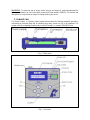
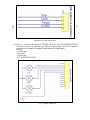
1. General view
The Screw Counter is a process control system that monitors the fastening assembly process by
calculating the fastening time and by checking how many screws are left to be tightened. The
system works by comparing the motor time on and off window, to a preset MIN/MAX value.
Fig. 1.0 Back panel
Fig 1.1 Front side

Fig 1.2 Bottom
2. Main features
- 9 indipendent programs
- Up to 99 screw for each program
- Min and max fastening time (accuracy: 0.01sec)
- User confirmation: active stop motor: push OK, to start a new cycle.
- In case of error, push ESC to continue (active stop motor).
- Password at the first starting and every time after the unit has been switched off
- Sequence of 4 programs
- Statistics: total number of correct screws done, wrong screws, cycles done, sequences done
- Connectors on the back panel with output signal of OK, NOK and END CYCLE
- Remote control of the system (optional)
- RS232 port
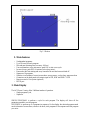
3. Main Display
The ACE Screw Counter offers 2 different modes of operation:
- Single program/Cycle,
- Sequence.
SINGLE PROGRAM: to perform a cycle for each program. The display will show all the
parameters needed to run the program.
SEQUENCE: to perform up to 4 programs in sequence. On the display the selected programs need
more information: screws done, screws to be done, total programs of the sequence and the program
you are in.

Fig 3.0 Single program: main screen
Fig 3.1 Sequence: main screen
If the screw has been done correctly, the unit will display the fastening time and the correct result of
the screw (Screw OK – fig. 3.2).
Fig 3.2 Screw OK
If the screw has been done wrongly, the unit will display the fastening time and the type of error
(fig. 3.3).

Fig. 3.3 Screw NOK
Errors can be:
- “Under min time”: when the torque is reached under the pre-set min time
- “Over max time”: when the fastening time is over the pre-set max time. In this case the
screwdriver will stop.
If the program you are in is finished, the unit will display the END CYCLE (fig. 3.4).
If the automatic reset is not active, this screen will be on until you push OK; instead if the automatic
reset is active, the unit will go to the next program.
Fig. 3.4 End program screen
In case of Sequence and last cycle, if the RESET is set on manual (fig. 3.5), push OK to re-start the
sequence; instead the unit will re-start the sequence automatically.
Fig. 3.5 End of sequence screen
Screw done display
This display shows the OK screws done. Its bigger digits ensure a more effective reading.
LED OK/ END/ NOK
To check more quickly the result of your fastening operation, 3 leds will help:
- GREEN: Screw OK
- YELLOW: end of program or end of sequence
- RED: Screw NOT-OK
Beep sounds
Beep sounds at the end of the screwing allow to check if the screwing itself is correct or not.
- 1 beep: Screw ok
- 3 beep: Screw not-ok
- 5 beep: end of cycle

3. Menu
To enter the menu, push ESC for 1 sec.
At the first starting, you must digit a password: through UP/DOWN keys, digit the number and
push OK to save it. Default password: 0000.
Menu:
1) Program: X
2) Screw : XX
3) Tmin : X.XX
4) Tmax : X.XX
5) Reset : YES/NO
6) Password
7) Sequence YES/NO
8) Sequence: XXXX
9) Statistic
To enter, select through UP/DOWN and push OK:
1) Program: to select the desired program. Once set, Pieces and Time will automatically be
loaded. The selected program will be used in “Single Program” mode.
Select the program through the UP/DOWN keys and push OK to save it or ESC to exit
without saving.
2) Screws: to select the number of pieces for each program.
Select the program through UP/DOWN keys and push OK to save it or ESC to exit without
saving.
3) Tmin: to set the minimum fastening time. Reaching the torque under the min time will result
in error. The min time must be lower than the max time. Select the program through
UP/DOWN keys and push OK to save it or ESC to exit without saving.
consente di inserire il tempo minimo di avvitatura. Se l'avvitatore arriverà in coppia in un
4) Tmax: to set the maximum fastening time. Reaching the torque over the max time will result
in error. In this case the screwdriver will stop and the operator will be advised on the display
and with 3 beep sounds. The max time must be higher than the min time.
Select the program through UP/DOWN keys and push OK to save it or ESC to exit without
saving.
5) RESET: if active, at the end of each program, push OK to start a new program. If not active,
the new program will start automatically. The end of the cycle will result on the display and
in a beep sound. Select the program through UP/DOWN keys and push OK to save it or
ESC to exit without saving.
6) Password: you can select a new password instead of the default 0000. Push OK and digit the
numbers through UP/DOWN, then push OK to save each value.
7) Sequence YES/NO: if YES, you can activate the sequence or a functioning sequence of the
pres-set programs (see § 8).
- Push OK to enter

- Through UP/DOWN keys, select “YES” to set the sequence or “NO” to remain in single
program
- Push OK to confirm.
Once you set the sequence, you can modify only the number of the screws, the min and the max
time but not the number of program you are in.
8) Sequence: you can set a sequence up to 4 programs. Each program can be repeated:
- Push OK to enter
- Set the number of cycle per program (2, 3, 4) through UP/DOWN and push O
- Set each single program through UP/DOWN and push OK
Once set the last program, the unit will save automatically the data. The sequence will be
shown on the display.
9) Statistic:
- Screws OK
- Screw NOT-OK
- Cycles done
- Sequences done correctly
Functioning:
- Push OK to enter
- All the data are visualized, then push OK to go on
- RESET ALL?: select YES through UP/DOWN to reset all the data or NO
- PRINT ALL: select YES through UP/DOWN to print all the data or NO
5.Connectors
Warning: a wrong connection may cause irreversible damage to this device, ensure that tensions
and connections are made by skilled technicians. Read the operating instructions before connecting
external systems and ensure that tensions and external signals are within the limits of the device.
Any tampering or damage caused by improper use of the device are not covered by warranty.
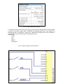
On the back panel, there are 2 connectors:
A) In/Out screwdriver
B) Output signals
C) Connection to external keyboard for a remote control
D) Remote suspension of cycle.
A) To be connected to the control unit:
1) Stop motor
2) Lever: start signal (lever pressed)
3) Torque: torque signal
4) 0 GND: common signal

Fig. 5.0
J1
connector to Kolver control units
B) Pins 1 to 4 send out the signals of OK/NOT-OK screws and CYLE/SEQUENCE END.
It features 2 relays to be used with up to 250VAC contacts: ideal to send for the signals to
external devices located in the medium-long distances or to light signals.
Pins are:
1) GND Output
2) OK Screw
3) NOK Screw
4) CYLE/SEQUENCE END
Fig 5.1 Signal connectors

Fig. 5.2 Signal connectors: features
C) Keyboard connections allow the ACE screw counter functions through remote controls parallel
to those on the screw counter itself, UP/DOWN not included useful only in the setting. The
keyboard has also a “part present”: when active, it disables the screwdriver and it also available on
your assembly line for a better control of the production cycle.
Controls are:
- 0 VDC
- OK
- ESC
- RESET
- Part present.
Fig. 5.2 Signal connectors on the keyboard

Warning: Do not connect buttons or other systems (for example remote systems such as PLC) with
external voltage and/or earth. Refer only to the figure 5.2.
Any tampering or damage caused by improper use of the device are not covered by warranty.
It’s possible to stop by remote the fastening cycle through a contact available on the back panel.
Closing this contact, the cycle is blocked and also the screwdriver. Useful as a part present on your
assembly line.
Fig. 5.3 Connection keyboard – part present
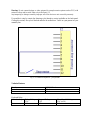
Technical features:
Transformer
12VDC 200mA
Nominal current
230mA
Max current
500mA
Keyboard Relay:
Nominal voltage
Pick-up Voltage
VDC
Drop-out Voltage
VDC
Max. allowable Voltage
VDC (at 20 )
24
18.0
1.20
31.2

GUARANTEE
1. This KOLVER product is guaranteed against defective workmanship or materials, for a
maximum period of 12 months following the date of purchase from KOLVER, provided that
its usage is limited to single shift operation throughout that period. If the usage rate exceeds
of single shift operation, the guarantee period shall be reduced on a prorata basis.
2. If, during the guarantee period, the product appears to be defective in workmanship or
materials, it should be returned to KOLVER or its distributors, transport prepaied, together
with a short description of the alleged defect. KOLVER shall, at its sole discretion, arrange
to repair or replace free of charge such items.
3. This guarantee does not cover repair or replacement required as a consequence of products
which have been abused, misused or modified, or which have been repaired using not
original KOLVER spare parts or by not authorized service personnel.
4. KOLVER accepts no claim for labour or other expenditure made upon defective products.
5. Any direct, incidental or consequential damages whatsoever arising from any defect are
expressly excluded.
6. This guarantee replaces all other guarantees, or conditions, expressed or implied, regarding
the quality, the marketability or the fitness for any particular purpose.
7. No one, whether an agent, servant or employee of KOLVER, is authorized to add to or
modify the terms of this limited guarantee in any way. However it’s possible to extend the
warranty with an extra cost. Further information at [email protected].
-
 1
1
-
 2
2
-
 3
3
-
 4
4
-
 5
5
-
 6
6
-
 7
7
-
 8
8
-
 9
9
-
 10
10
-
 11
11
-
 12
12


Kolver ACE Screw Counter Operator's Handbook Manual
- Type
- Operator's Handbook Manual
Ask a question and I''ll find the answer in the document
Finding information in a document is now easier with AI
Other documents
-
Carel UU14 User manual
-
 Duerkopp Adler 745-35 S Operating instructions
-
Contec CX-100n-DC5311-C02 Owner's manual
-
 Duerkopp Adler 745-35 S User manual
-
Acer 4320 User manual
-
-
Aspire Digital 7520G User manual
-
Contec BX-100n Owner's manual
-
-
Acer 4520G User manual

