
Grinding & Polishing
MODEL BMG-780 GRINDER
SECTION 2 SAFETY INSTRUCTIONS
1
OPERATING MANUAL
JANUARY 2008
MODEL
BMG-535
Planetary Grinder
Technical Data 1
Safety Instructions 2
General 3
Transport 4
Initial Operation 5
Operation 6
Maintenance 7
Electrical Systems 8
Fault Diagnosis 9
Spare Parts 10
Grinding & Polishing

MODEL BMG-535 GRINDER
SECTION 1 TECHNICAL DATA
1
OPERATING MANUAL
APRIL 2009
Grinding & Polishing
1.1 Rating
1.2 Unit specifications
1.3 Operative range and correct usage
1.4 Stand-by power supply
1.5 Machine type designation
CONTENTS – SECTION 1

MODEL BMG-535 GRINDER
SECTION 1 TECHNICAL DATA
2
OPERATING MANUAL
APRIL 2009
Grinding & Polishing
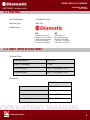
Unit / Designation: Grinding Machine
Machine Type: BMG-535
Manufacturer:
Technical Data:
Grinding Machine BMG-535
Power Consumption 7.5 kW
Connected loads 220V, Three phase, 25.2A
Connected loads 440V, Three phase, 14.4A
Dimensions:
BMG-535
Length 37.5 in / 950 mm
Width 23 in / 580 mm
Height 49.25 in / 1250 mm
Weight 617 lbs / 280 kg
US BV
13201 North Santa Fe Utrechthaven 12
Oklahoma City, OK 73114 3433 PN Nieuwegein
United States of America THE NETHERLANDS
Local: 405-478-3440 T +31(0)30 – 601 88 66
toll-free: 800-256-3440 F +31(0)30 – 601 83 33
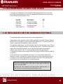
1.1 RATING
1.2 UNIT SPECIFICATIONS

MODEL BMG-535 GRINDER
SECTION 1 TECHNICAL DATA
3
OPERATING MANUAL
APRIL 2009
Grinding & Polishing
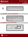
1.3 OPERATIVE RANGE AND CORRECT USAGE
The BMG-535 is exclusively designed to process horizontal
surfaces. The machine must not be used for other purposes. The
manufacturer will not be liable for damage resulting from
incorrect usage. In these cases, the user takes responsibility for
all risks.
1.4 STAND-BY SUPPLY (GENERATOR)
If the BMG-535 is to be operated using power from a generator,
the generator must be operated in accordance with the current
U. S. National Electric Code guidelines or European VDE
standards, as appropriate (this applies, but is not limited to, the
protective earth conductor in particular) in order to ensure that all
safety devices are functioning and to eliminate possible damage
to electrical components.
1.5 MACHINE TYPE DESIGNATION
BMG – 535
Product Type
Working width in mm

MODEL BMG-535 GRINDER
SECTION 2 SAFETY INSTRUCTIONS
4
OPERATING MANUAL
APRIL 2009
Grinding & Polishing
2.1 Warnings and symbols
2.2 Organizational measures
2.3 Personnel selection and qualification
2.4 Safety precautions applicable to some operating sequences
2.5 Special work within the scope of use of the equipment and maintenance
activities as well as repairs during operation
2.6 Definition of the safety off position
2.7 General Safety Considerations
2.8 Electrical engineering regulations
CONTENTS – SECTION 2

MODEL BMG-535 GRINDER
SECTION 2 SAFETY INSTRUCTIONS
5
OPERATING MANUAL
APRIL 2009
Grinding & Polishing
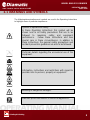
The following denominations and symbols are used in the Operating Instructions
to highlight areas of particular importance:
2.1 WARNINGS AND SYMBOLS
Symbol of operational safety.
In these Operating Instructions this symbol will be
shown next to all safety precautions that are to be
followed to maximize safety and equipment
performance. Follow these instructions and take
special care in these circumstances. In addition to
these instructions, the general safety precautions and
accident prevention guidelines are also to be followed.
Particular details regarding the economical use of the
equipment.
Information, instructions and restrictions with regard to
possible risks to persons, property or equipment.
Warning of dangerous voltages.
Indicates protective devices in electrical appliances.

MODEL BMG-535 GRINDER
SECTION 2 SAFETY INSTRUCTIONS
6
OPERATING MANUAL
APRIL 2009
Grinding & Polishing
In addition to these Operating Instructions, general and legal regulations
regarding accident prevention and environmental protection must be complied
with per local regulations.
Such duties may, for example, relate to the handling of hazardous substances, or
the provision and wearing of personal protection equipment, as well as
compliance with traffic regulations.
The Operating Instructions must be supplemented by other instructions, including
the duty to supervise and report incidents relating to particular working practices,
for example work organization, work procedures and personnel safety.
Personnel entrusted with working with the machine must read and understand
the Operating Instructions before starting work, paying specific attention to the
Safety information. To read these instructions after work has commenced is too
late. This particularly applies to incidental activities such as setting up the
equipment, carrying out maintenance work or training staff to work with the
machine.
Indicates where consultation with the manufacturer is
required.
Instructions relating to periodic checks.
2.2 ORGANIZATIONAL MEASURES
These Operating Instructions are to be kept with the machine, and
must be within reach at all times!
Reference to important instructions contained in the
Operating Instructions.

MODEL BMG-535 GRINDER
SECTION 2 SAFETY INSTRUCTIONS
7
OPERATING MANUAL
APRIL 2009
Grinding & Polishing
From time to time the working practices of the operators are to be checked by a
supervisor, especially regarding awareness of safety and hazards.
Operators must tie back long hair, and not wear loose clothing or jewelry
including rings. There is a risk of injury by items getting caught, or being drawn
into moving machinery.
:
All safety and hazard notices at or on the machine must be kept complete and
legible.
If safety-critical changes occur to the machine or its working method, the
machine must be shut down immediately. The cause of the fault must be
established and remedied.
This applies in particular to the fitting and adjustment of safety devices.
Spare parts must comply with the technical requirements specified by the
manufacturer. This is always guaranteed if original spare parts are used.
Intervals for recurring checks and inspections specified in these Operating
Instructions must be complied with.
To perform maintenance work correctly, it is imperative to be equipped with the
proper tools for the task.
The location and the operation of fire extinguishers must be made known on
each work site.
Take note of the facilities for reporting and fighting fires.
Use personnel protection equipment if necessary or required by
local regulations! Take notice of all safety and hazard notices on
the machine!
Changes, additions or conversions to the machine must not be
made, without the manufacturer’s permission!

MODEL BMG-535 GRINDER
SECTION 2 SAFETY INSTRUCTIONS
8
OPERATING MANUAL
APRIL 2009
Grinding & Polishing
Fundamental duties:
Work on the machine may only be undertaken by trained personnel.
Only trained personnel may be employed. Note the statutory minimum age.
Clearly specify the responsibilities of personnel for operation, setting up,
servicing and maintenance work.
Make sure that only authorized personnel operate or work on the machine.
Define responsibilities of the machine operator, with regard to traffic safety
regulations, and inform him not to take instructions from third parties who may
not be complying with the local safety requirements.
Personnel, who are being trained to operate equipment, may only use the
machine under constant supervision of an experienced person.
.
Do not allow any method of working that impairs safety.
Recognized official procedures have to be used to ensure the machine is
operated in the safest and best conditions.
2.3 PERSONNEL SELECTION AND QUALIFICATION
Work on electrical equipment may only be performed by a skilled
electrician or by trained persons under the supervision of a skilled
electrician, as well as in accordance with the local electrical
engineering regulations.
2.4 SAFETY PRECAUTIONS APPLICABLE TO SOME
OPERATING SEQUENCES
Only operate the machine when all safety devices, and related
safety equipment, are present and operational!

MODEL BMG-535 GRINDER
SECTION 2 SAFETY INSTRUCTIONS
9
OPERATING MANUAL
APRIL 2009
Grinding & Polishing
Check the machine visually for any damage and defects at least once a day.
In the event of operational malfunctions the machine must be shut down
immediately and secured.
Faults must be immediately remedied.
Carry out the switch on, and switch off, operations in accordance with the
operations manual.
Before turning on the machine verify that no one can be endangered when the
machine starts up.
Do not turn off the dust collector while the machine is running.
Secure the work area around the machine in public areas
providing a safety distance of at least 6.5 feet (2 meters) from the
machine.
All persons in the proximity of the machine must wear ear
protectors and safety shoes. In addition, the machine operator
must wear close fitting protective clothing.
Use only extension cables, used for extending the main cable, that
are sized and marked in accordance with the overall power
consumption of the machine and valid U. S. National Electric Code
guidelines or European VDE standards, as appropriate.

MODEL BMG-535 GRINDER
SECTION 2 SAFETY INSTRUCTIONS
10
OPERATING MANUAL
APRIL 2009
Grinding & Polishing
Mechanical servicing work:
Put the machine in the Safety off position as described in Section 2.6 before
carrying out any service work on the machine.
Follow any special safety instructions in sections on servicing the machine. See
Section 7.
Service and maintenance intervals specified in these Operating Instructions, as
well as information on the replacement of parts must be undertaken and/or
complied with.
These activities may only be undertaken by qualified personnel.
The operator must be given information about maintenance and work procedures
before starting the cleaning process. This includes, but is not limited to the
following:
• Procedures that are related to normal operation
• Methods of tools adjustment on the machine, and its safety devices,
• All “ON and OFF” functions that have to be carried out according to the
operation manual
• Methods for maintenance and repair.
If the equipment is switched off in order to carry out maintenance, repair, or
adjustment, it must be secured against unintended restart.
Switch OFF and disconnect the machine from the power supply.
See Section 2.6 Safety off position for specific details.
Always dispose of the contents of the dust bin or of a connected dust collector
before loading the machine onto a vehicle.
2.5 SPECIAL WORK WITHIN THE SCOPE OF USE OF THE
EQUIPMENT AND MAINTENANCE ACTIVITIES AS WELL
AS REPAIRS DURING OPERATION

MODEL BMG-535 GRINDER
SECTION 2 SAFETY INSTRUCTIONS
11
OPERATING MANUAL
APRIL 2009
Grinding & Polishing
Observe the local waste disposal regulations; in uncertain situations ask the next
higher authority.
Do not use any aggressive cleaning materials.
Only use lint-free cleaning cloths.
Always verify that any bolted connections that were loosened during service and
maintenance work are properly secure and tight.
If safety devices need to be removed or dismantled during service and repair,
these safety devices must be reinstalled, and inspected immediately after
completion of the servicing and repair work.
Make sure that process materials and replaced parts are disposed of safely and
in an environmentally friendly manner.
Make sure that electrical components used for replacement purposes comply
with the original parts and are correctly adjusted if necessary.
Definition
: The machine is in a safe condition where it cannot be a hazard.
Putting the equipment in the Safety off position involves:
• Switching off the machine.
• Switching off the dust collector (if being used).
• Waiting for all drives to stop.
• Disconnecting all power from the power source.
• Securing against unintended restart.
Work on electrical equipment may only be performed by a skilled
electrician or by trained persons under the supervision of a skilled
electrician, as well as in accordance with the local electrical
engineering regulations.
2.6 DEFINITION OF THE SAFETY OFF POSITION

MODEL BMG-535 GRINDER
SECTION 2 SAFETY INSTRUCTIONS
12
OPERATING MANUAL
APRIL 2009
Grinding & Polishing
The electrical components of the equipment must be inspected regularly. Defects
such as loose connections or scorched cables must be replaced immediately.
Call a skilled electrician or our Customer Service.
A second person must be in attendance while the electrician is working on the
equipment.
The work area must be secured against any third party entering the work area,
by means of a red and white safety chain and a danger sign. Use only tools that
are insulated against electricity.
Only start work after you are familiar with the electrical engineering regulations
that apply to the local area.
Only use multi-meters that comply with the regulations when troubleshooting.
From time to time check multi-meters to ensure that they are operating correctly.
2.7 GENERAL SAFETY CONSIDERATIONS
Any machine, if it is not used according to regulations, may be
hazardous during operation, set-up and servicing. The machine
owner is responsible for compliance with the safety regulations
during operation and maintenance, and for the use of safety
devices supplied with the machine, as well as the provision of
appropriate additional safety devices!
2.8 ELECTRICAL ENGINEERING REGULATIONS
Work on electrical equipment may only be performed by a skilled
electrician or by trained persons under the supervision of a skilled
electrician, as well as in accordance with the local electrical
engineering regulations.
Use only extension cables, used for extending the main cable, that
are sized and marked in accordance with the overall power
consumption of the machine and the U. S. National Electric Code
guidelines or European VDE standards, as appropriate.

MODEL BMG-535 GRINDER
SECTION 3 GENERAL
13
OPERATING MANUAL
APRIL 2009
Grinding & Polishing
3.1 Range of application
3.2 Scope of supply
3.3 Description of the machine
3.4 Operating elements
3.5 Electric components
3.6 Upper part
3.7 Lower part
3.8 Tensioner upper belt
3.9 Tensioner lower belt
3.10 Pulley
3.11 Center pulley
3.12 Contra pulley
3.13 Driving pulley
3.14 Diamond tool holder
3.15 Diamond Tooling
3.16 Care and maintenance
CONTENTS – SECTION 3

MODEL BMG-535 GRINDER
SECTION 3 GENERAL
14
OPERATING MANUAL
APRIL 2009
Grinding & Polishing
Typical ranges of applications for the BMG-535 are for example:
• To remove undulated concrete surfaces
• To prepare the surface for coatings
• To polish the surface
• To remove coating defects
• To remove glue residue
Scope of supply of the machine:
• Grinding machine (BMG-535)
• Dust hose (Optional)
• Operating manual (1x)
3.1 RANGE OF APPLICATION
3.2 SCOPE OF SUPPLY

MODEL BMG-535 GRINDER
SECTION 3 GENERAL
15
OPERATING MANUAL
APRIL 2009
Grinding & Polishing
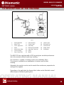
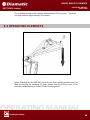
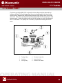
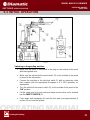
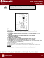
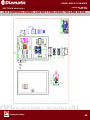
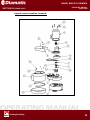
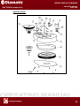
Fig. 3.1
1 Steering Handle 8 Lower Housing 15 Lower Frame
2 Water Tank 9 Center Pulley 16 Electrical Plug
3 Cover, Upper Part 10 Lower Belt 17 Control Panel
4 Motor 11 Diamond Tool Holders 18 Safety Switch
5 Motor Mount Plate 12 Lower Belt Tensioner
19
Pushbutton
6 Cover Housing 13 Pulley
7 Dust Control Seal 14 Wheel
The BMG-535 has a working width of 535 mm and gives excellent performance
due to its economic efficiency and easy handling.
The machine is capable of leveling uneven and undulating floors.
This process is suitable for an optimization of surfaces prior to blast
cleaning.
Alternately, the machine can be used to smooth floor surfaces as preparation for
coatings to be applied.
Depending on the application the diamond disc holder can be fitted with several
different types of diamond-grinding discs.
3.3 DESCRIPTION OF THE MACHINE

MODEL BMG-535 GRINDER
SECTION 3 GENERAL
16
OPERATING MANUAL
APRIL 2009
Grinding & Polishing
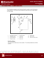
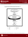
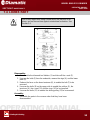
The individual tooling heads rotate at approximately 1250 revs/min. The Lower
Housing rotates at approximately 82 revs/min.
Fig. 3.2
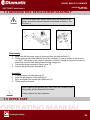
Before Switching on the BMG-535, the front part of the grinding machine
must be
lifted by pushing the handgrip (1) down toward floor level till the front of the
machine is approximately 4 inches (10 cm) from the ground.
3.4 OPERATING ELEMENTS

MODEL BMG-535 GRINDER
SECTION 3 GENERAL
17
OPERATING MANUAL
APRIL 2009
Grinding & Polishing
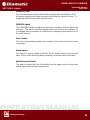
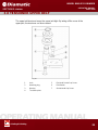
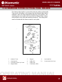
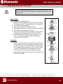
The Pushbutton mounted on the Steering Handle is used to control all elements
of the machine. The Control Panel contains the main disconnect, safety switch,
and hour meter.
Fig. 3.3
1 Pushbutton Enclosure 5 Panel Enclosure 9 Safety Switch
2 FWD/REV Switch 6 Panel Plug 10 Hour Counter
3 Start/Stop Buttons 7 Motor Plug 11 Main Disconnect Switc
h
4 Emergency Stop 8 Panel Lock
Start/Stop Buttons
The green start button turns on the machine. The red stop button turns off the
machine.
3.5 ELECTRIC COMPONENTS

MODEL BMG-535 GRINDER
SECTION 3 GENERAL
18
OPERATING MANUAL
APRIL 2009
Grinding & Polishing
Emergency Stop
This red mushroom-shaped switch when pressed will immediately cut off
the power supply to the panel and motor and bring the machine to rest. To
restart the machine the switch must be reset.
FWD/REV Switch
The FWD/REV switch changes the direction of rotation of the head of the
machine. This switch must be changed when the head is not rotating, if it
is changed during operation it could result in damage to the machine or to
the work surface.
Hour Counter
The hour counter simply monitors the number of hours the machine has been
in operation.
Safety Switch
This switch is spring loaded; it will turn off the power supply if the operator
loses control of the machining while operating and must be worn at all times.
Main Disconnect Switch
This switch controls the flow of electricity from the power source to the panel
and all subsequent electrical components.

MODEL BMG-535 GRINDER
SECTION 3 GENERAL
19
OPERATING MANUAL
APRIL 2009
Grinding & Polishing
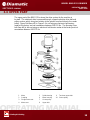
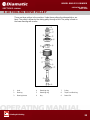
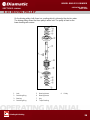
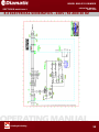
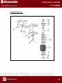
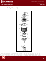
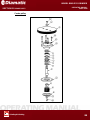
The upper part of the BMG-535 is where the drive system for the machine is
located. The rotational drive is powered through a speed reduction drive belt and
pulley system, which also gives rotation to the grinder head and drive to the center
pulley. Upper Belt (item #3) in Figure 3.4 is set using an electronic belt tension
meter at the factory and set somewhere between 200-215 Hz. The Housing Drive
belt (item #9) is also set using an electronic belt tension meter at the factory and set
somewhere between 160-170 Hz.
Fig. 3.4
1 Motor 5 Spider bearing 9 Tensioner upper belt
2 Coupling 6 Motor housing 10 Contra pulley
3 Flange motor seat 7 Center pulley
4 Motor seat 8 Upper belt
3.6 UPPE
R
PART
Page is loading ...
Page is loading ...
Page is loading ...
Page is loading ...
Page is loading ...
Page is loading ...
Page is loading ...
Page is loading ...
Page is loading ...
Page is loading ...
Page is loading ...
Page is loading ...
Page is loading ...
Page is loading ...
Page is loading ...
Page is loading ...
Page is loading ...
Page is loading ...
Page is loading ...
Page is loading ...
Page is loading ...
Page is loading ...
Page is loading ...
Page is loading ...
Page is loading ...
Page is loading ...
Page is loading ...
Page is loading ...
Page is loading ...
Page is loading ...
Page is loading ...
Page is loading ...
Page is loading ...
Page is loading ...
Page is loading ...
Page is loading ...
Page is loading ...
Page is loading ...
Page is loading ...
Page is loading ...
Page is loading ...
Page is loading ...
Page is loading ...
Page is loading ...
Page is loading ...
Page is loading ...
Page is loading ...
Page is loading ...
Page is loading ...
Page is loading ...
Page is loading ...
Page is loading ...
Page is loading ...
Page is loading ...
Page is loading ...
Page is loading ...
Page is loading ...
Page is loading ...
Page is loading ...
Page is loading ...
Page is loading ...
Page is loading ...
Page is loading ...
Page is loading ...
Page is loading ...
Page is loading ...
Page is loading ...
Page is loading ...
Page is loading ...
Page is loading ...
-
 1
1
-
 2
2
-
 3
3
-
 4
4
-
 5
5
-
 6
6
-
 7
7
-
 8
8
-
 9
9
-
 10
10
-
 11
11
-
 12
12
-
 13
13
-
 14
14
-
 15
15
-
 16
16
-
 17
17
-
 18
18
-
 19
19
-
 20
20
-
 21
21
-
 22
22
-
 23
23
-
 24
24
-
 25
25
-
 26
26
-
 27
27
-
 28
28
-
 29
29
-
 30
30
-
 31
31
-
 32
32
-
 33
33
-
 34
34
-
 35
35
-
 36
36
-
 37
37
-
 38
38
-
 39
39
-
 40
40
-
 41
41
-
 42
42
-
 43
43
-
 44
44
-
 45
45
-
 46
46
-
 47
47
-
 48
48
-
 49
49
-
 50
50
-
 51
51
-
 52
52
-
 53
53
-
 54
54
-
 55
55
-
 56
56
-
 57
57
-
 58
58
-
 59
59
-
 60
60
-
 61
61
-
 62
62
-
 63
63
-
 64
64
-
 65
65
-
 66
66
-
 67
67
-
 68
68
-
 69
69
-
 70
70
-
 71
71
-
 72
72
-
 73
73
-
 74
74
-
 75
75
-
 76
76
-
 77
77
-
 78
78
-
 79
79
-
 80
80
-
 81
81
-
 82
82
-
 83
83
-
 84
84
-
 85
85
-
 86
86
-
 87
87
-
 88
88
-
 89
89
-
 90
90


Ask a question and I''ll find the answer in the document
Finding information in a document is now easier with AI
Other documents
-
Kyosho MDW301 MJ Aluminum Upper Cover(FWD) User manual
-
Diamond Grinder CC200 User manual
-
Denzel Машина шлифовальная угловая AG125-1100 Owner's manual
-
XtremepowerUS 61058-H User manual
-
 National Flooring Equipment 5274 Operating instructions
-
Husqvarna PG 400 Owner's manual
-
Worker COCO3900 User manual
-
 National Flooring Equipment 3432 Operating & Service Manual
-
Blastrac BGS-250-115 Owner's manual
-
 National Flooring Equipment GP700 Operating & Service Manual


