CompuSTAR RS1B-DC3 User manual
- Category
- Remote starters
- Type
- User manual
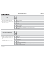
CompuSTAR RS1B-DC3 is an advanced remote starter system that allows you to start your vehicle's engine, lock and unlock the doors, and activate the security system, all from the convenience of your existing key fob. It features a tachometer programming procedure for accurate engine control, aftermarket remote programming for up to four additional remotes, and a valet mode for temporarily disabling the remote start function.
CompuSTAR RS1B-DC3 is an advanced remote starter system that allows you to start your vehicle's engine, lock and unlock the doors, and activate the security system, all from the convenience of your existing key fob. It features a tachometer programming procedure for accurate engine control, aftermarket remote programming for up to four additional remotes, and a valet mode for temporarily disabling the remote start function.


-
 1
1
-
 2
2
-
 3
3
-
 4
4
-
 5
5
-
 6
6
-
 7
7
-
 8
8
-
 9
9
-
 10
10
-
 11
11
-
 12
12


CompuSTAR RS1B-DC3 User manual
- Category
- Remote starters
- Type
- User manual
CompuSTAR RS1B-DC3 is an advanced remote starter system that allows you to start your vehicle's engine, lock and unlock the doors, and activate the security system, all from the convenience of your existing key fob. It features a tachometer programming procedure for accurate engine control, aftermarket remote programming for up to four additional remotes, and a valet mode for temporarily disabling the remote start function.
Ask a question and I''ll find the answer in the document
Finding information in a document is now easier with AI
Related papers

Other documents
-
Firstech 2017 Installation guide
-
Idatalink 2021 Hyundai Kona Std Key Automatic Owner's manual
-
Idatalink ALCA 64K Installation guide
-
Idatalink ADS-ALCA Install Manual
-
-
-
![Omega LinkOEM-IDS(RS)-BM1-[OL-RS-BM1]-EN](//vs1.manuzoid.com/store/data/001238179_2-8717a40a333d00e07cadc565577362e8-160x210.png) Omega Link OEM-IDS(RS)-BM1-[OL-RS-BM1]-EN Install Manual
Omega Link OEM-IDS(RS)-BM1-[OL-RS-BM1]-EN Install Manual
-
-
-
 idatastart OEM-IRS-BM1-ADS-BM1-EN Install Manual
![Omega LinkOEM-IDS(RS)-BM1-[OL-RS-BM1]-EN](http://vs1.manuzoid.com/store/data/001238179_2-8717a40a333d00e07cadc565577362e8-160x210.png)
