ShelterLogic 86071.0 Operating instructions

Type
Operating instructions
05_10B163_0EPage 1
30'W x 16' or 20'H Peak Style Shelter
Frame Assembly Instructions
Before you start: 3+ individual recommended for assembly.Assembly time is dependent upon the size
of your building. Allow approximately 15 minutes for every foot in building length.
Please read instructions COMPLETELY before assembly. This shelter MUST be securely anchored.
THIS IS A TEMPORARY STRUCTURE AND NOT RECOMMENDED AS A PERMANENT STRUCTURE.
1-800-524-9970
1-800-559-6175
Canada:
RECOMMENDED TOOLS
8/27/10
150 Callender Road
Watertown, CT 06795
www.shelterlogic.com
FOR SIZES:
30' W. x 16' H. 30' W. x 20' H.
05_10B163_0EPage 2
Risk of re. Do not smoke or use open ame devices (including grills, re pits, deep fryers, smokers or
lanterns) in or around the shelter. DO NOT store ammable liquids (gasoline, kerosene, propane, etc.) in
or around your shelter. Do not expose top or sides of the shelter to open re or other ame source.
WARNING:
CAUTION:
PROPER ANCHORING OF THE FRAME IS THE RESPONSIBILITY OF THE CONSUMER.
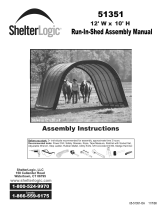
ShelterLogic
®
, LLC
is not responsible for damage to the unit or the contents from acts of nature. Any shelter that is not anchored
securely has the potential to y away causing damage, and is not covered under the warranty. Periodically check the anchors to ensure
stability of shelter. ShelterLogic
®
, LLC cannot be responsible for any shelter that blows away. NOTE: Your shelters cover can be
quickly removed and stored prior to severe weather conditions. If strong winds or severe weather is forecast in your area, we
recommend removal of cover.
PROPER ANCHORING AND INSTALLATION OF FRAME:
A tight cover ensures longer life and performance. Always maintain a tight cover. Loose fabric can accelerate
deterioration of cover fabric. Immediately remove any accumulated snow or ice from the roof structure with a
broom, mop or other soft-sided instrument. Use extreme caution when removing snow from cover- always
remove from outside the structure. DO NOT use hard-edged tools or instruments like rakes or shovels to
remove snow. This could result in punctures to the cover. DO NOT use bleach or harsh abrasive products to
clean the fabric cover. Cover is easily cleaned with mild soap and water.
Covered by U.S. Patents and patents pending: 6,871,614; 6,994,099; 7,296,584; D 430,306; D 415,571; D 414,564; D 409,310; D 415,572
CARE AND CLEANING:
Prior to installation, consult with all local municipal codes regarding installation of temporary shelters.
Choose the location of your shelter carefully. DANGER: Keep away from electrical wires. Check for
overhead utility lines, tree branches or other structures. Check for underground pipes or wires before
you dig. DO NOT install near roof lines or other structures that could shed snow, ice or excessive run
off onto your shelter. DO NOT hang objects from the roof or support cables.
ATTENTION:
This shelter product is manufactured with quality materials. It is designed to t the ShelterLogic
®
, LLC custom fabric cover included.
ShelterLogic
®
, LLC Shelters offer storage and protection from damage caused by sun, light rain, tree sap, animal - bird excrement
and light snow. Please anchor this ShelterLogic
®
, LLC structure properly. See manual for more anchoring details. Proper anchoring,
keeping cover tight and free of snow and debris is the responsibility of the consumer. Please read and understand the installation detail,
warnings and cautions prior to beginning installation. If you have any questions call the customer service number listed below. Please
refer to the warranty card inside this package.
DANGER:
Use CAUTION when erecting the frame. Use safety goggles during installation. Secure and bolt together
overhead poles during assembly. Beware of pole ends.
REPLACEMENT PARTS, ASSEMBLY, SPECIAL ORDERS:
Genuine ShelterLogic
®
, LLC replacement parts and accessories are available from the factory, including anchoring kits for nearly any
application, replacement covers, wall and enclosure kits, vent and light kits, frame parts, zippered doors and other accessories. All
items are shipped factory direct to your door.
This shelter carries a full limited warranty against defects in workmanship. ShelterLogic
®
, LLC warrants to the Original Purchaser that if
properly used and installed, the product and all associated parts, are free from manufacturers defects for a period of:
1 YEAR FOR COVER FABRIC, END PANELS AND FRAMEWORK
Warranty period is determined by date of shipment from ShelterLogic
®
, LLC for factory direct purchases or date of purchase from an authorized
reseller, (please save a copy of your purchase receipt). If this product or any associated parts are found to be defective or missing at the time of receipt,
ShelterLogic
®
, LLC will repair or replace, at it’s option, the defective parts at no charge to the original purchaser. Replacement parts or repaired parts
shall be covered for the remainder of the Original Limited Warranty Period. All shipping costs will be the responsibility of the customer. Parts and replace-
ments will be sent C.O.D. You must save the original packaging materials for shipment back. If you purchased from a local dealer, all claims must have a
copy of original receipt. After purchase, please ll out and return warranty card for product registration. Please see warranty card for more details.
WARRANTY:
QUESTIONS - CLAIMS - SPECIAL ORDERS? CALL OUR CUSTOMER SERVICE HOTLINE:
U.S. CUSTOMER SERVICE: 1-800-524-9970 INTERNATIONAL CUSTOMER SERVICE: 001-860-945-6442 CANADA CUSTOMER SERVICE: 1-800-559-6175
HOURS OF OPERATION: MON-FRI 8:30AM-8:00PM EST, SAT-SUN 8:30AM-5:00PM EST.
080310
05_10B163_0EPage 3
30'W x 16' or 20'H Peak Style Frame Assembly 10B163
Please read and understand instructions completely before assembly.
Lay out frame parts as shown.
End Rib
End Rib
Middle Ribs
Wind Brace
Wind Brace
Cover
Rails
Cross
Rails
Top
Rail
1
2
3
4
5
6
7
8
9
10
29
24
10
11
10
13
16
19
2
22
10
16' High
10
11
1
4
10
12
12
12
11
10
29
13,16,19
7
7
22
22
9
11
28
24
10
3
4
2
2
20,17,19
20
17
19
21,17,19
1
8
1
8
10
12
10
10
10
10
29
14
18
19
15
17
19
16
19
16
19
21,17
19
21,17
19
21,17
19
14
18
19
14
18
19
15
13
16
19
14
26
19
15
14
18
19
14,26,19
14
18
19
29
14
26
19
24
11
28
3
5,27,19
5,26,19
ItEM no.
DESCRIPTIOn
PART NO.
1
RAFTER, 60X1600X2,6T SWG 2H GRY 800384
2
RAFTER PIPE, 60X1885,9X2,6T SWG 3H GRY 800385
3
LEG BEND, 60 X1949,4X2,6T SWG 4H GRY 800435
4
SIDE BEND, 60X1866X2,6T SWG 3 H GRY 800386
5
TOP CREST, 60X1151,3X2,6T 3H GRY 800383
6
TRUSS BRACE, PLAIN 38X1808X1,2T GRY 800389
7
TRUSS BRACE, 38X828X1,2T, [32-5/8 H-H] GRY 800391
8
TRUSS BRACE, SWG 38X1866,7X1,2T [71-3/16 H-H] 800390
9
UPRIGHT, 60X1949.5X2.6T SWG 3H GRY 800436
10
CROSS RAIL SWEDGED, 50-1/2" X 1 3/8"DIA 11102
11
CROSS RAIL PLAIN END 2H, 48-1/2"X1-3/8" 11104
12
COVER RAIL 45" PLAIN ENDS 2 HOLES 11105
13
FOOT, WELDED FOR 2-3/8 PIPE
14
SHELTERLOCK ANTI-LOCK DEVICE 60X38MM 800372
15
1" RATCHET W/24" PLAIN STRAP SEWN ON WB601RS24
16
BOLT, CARRIAGE 5/16-18 X 2-3/4" 11131
17
BOLT, CARRIAGE, 5/16"X 2-1/4"LONG 11130
18
BOLT, CARRIAGE 5/16-18 X 4-1/8" 800454
19
NUT, HEX 5/16-18" 00690
20
3 WAY COVER CLAMP 11106
21
4 WAY COVER RAIL CLAMP 11107
22
ANCHOR, EARTH 1-5/8" PIPE, SMALL 00828
23
DRIVING RD FOR EARTH ANCHOR 3/8"X30" 00825
24
WIND BRACE, 38X1679,6X1,2T GRY 800440
2" RATCHET W/24" PLAIN STRAP SEWN ON WB602RS1
26
BOLT, CARRIAGE 5/16-18 X 4-1/2" 11134
27
BOLT, 5/16"X 4" LONG 11133
25
800859
28
BOTTOM CROSS RAIL
802051
29
BOTTOM CROSS RAIL, SWEDGED
802050
ATTENTION:
FOR MISSING OR
REPLACEMENT PARTS
OR QUESTIONS,
PLEASE CONTACT
CUSTOMER SERVICE:
1.800.524.9970
CANADA 1.800.559.6175
www.shelterlogic.com
150 Callender Road
Watertown, CT 06795
05_10B163_0EPage 4
30'W x 16' or 20'H Peak Style Frame Assembly 10B163
Please read and understand instructions completely before assembly.
Lay out frame parts as shown.
ATTENTION:
FOR MISSING OR
REPLACEMENT PARTS
OR QUESTIONS,
PLEASE CONTACT
CUSTOMER SERVICE:
1.800.524.9970
CANADA 1.800.559.6175
www.shelterlogic.com
150 Callender Road
Watertown, CT 06795
1
23
6
5
24
3,28,16
8
23
9
22
2
23
3
24
9
22
10
14
16
9
8
1
2
9
7
7
7
31
5
19
21
9
1
25
14
26
25
31
23
2
22
22
17
13
16
17,13,16
18,13,16
1
4
1
4
4
8
9
21
26
9
9
7
12
15
16
9
9
9
31
30
8
11
11
13
16
10
14
16
14
14
16
12
15
16
12
15
16
11
29,16
18,13,16
18,13,16
18,13,16
19
11
12
28
16
10
14
16
12
15
16
12
28
16
30
8
9
31
25
26
21
19
20' High
End Rib
End Rib
Middle Ribs
Wind Brace
Wind Brace
Cover
Rails
Cross
Rails
Top
Rail
ItEM
DESCRIPTIOn
PART NO.
1
RAFTER, 60X1600X2,6T SWG 2H GRY 800384
2
SIDE BEND, 60X1866X2,6T SWG 3 H GRY 800386
3
TOP CREST, 60X1151,3X2,6T 3H GRY 800383
4
TRUSS BRACE, PLAIN 38X1808X1,2T GRY 800389
5
TRUSS BRACE, 38X828X1,2T, [32-5/8 H-H] GRY 800391
6
TRUSS BRACE, SWG 38X1866,7X1,2T [71-3/16 H-H] 800390
7
COVER RAIL 45" PLAIN ENDS 2 HOLES 11105
8
CROSS RAIL PLAIN END 2H, 48-1/2"X1-3/8" 11104
9
CROSS RAIL SWEDGED, 50-1/2" X 1 3/8"DIA 11102
10
FOOT, WELDED FOR 2-3/8 PIPE 800088
11
1" RATCHET W/24" PLAIN STRAP SEWN ON WB601RS24
12
SHELTERLOCK ANTI-LOCK DEVICE 60X38MM 800372
13
BOLT, CARRIAGE 5/16-18 X 2 1/4" 11130
14
BOLT, CARRIAGE, 5/16"X 2-3/4"LONG 11131
15
BOLT, CARRIAGE 5/16-18 X 4 1/8” 800454
16
NUT, HEX 5/16-18 00690
17
3 WAY COVER CLAMP 11106
18
4 WAY COVER RAIL CLAMP 11107
19
ANCHOR, EARTH 1-5/8" PIPE, SMALL 00828
20
DRIVING RD FOR EARTH ANCHOR 3/8"X30" 00825
21
LEG BEND, 60 X1949,4X2,6T SWG 4H GRY 800435
22
RAFTER PIPE, 60X1885,9X2,6T SWG 3H GRY 800385
23
UPRIGHT EXT, 60X1320.8X2.6T 2H GAL 800438
24
UPRIGHT, 60X1949.5X2.6T SWG 3H GRY 800436
25
WIND BRACE, 38X1679,6X1,2T GRY 800440
26
WIND BRACE, 38X1715X1,2T GRY 800442
2" RATCHET W/24" PLAIN STRAP SEWN ON WB602RS1
28
BOLT, CARRIAGE 5/16-18 X 4-1/2" 11134
29
BOLT, 5/16"X 4"LONG 11133
27
30
BOTTOM CROSS RAIL
802051
31
BOTTOM CROSS RAIL, SWEDGED
802050
800859
05_10B163_0EPage 5
BASIC FRAME ASSEMBLY
NOTE FOR FRAME EXTENSION KIT: 30' x 20' x 16' is the base frame dimension. Your model may have more
middle ribs than shown in the illustrations. You will receive one extra rib for every extra 4 feet of building length
that you purchase. The basic frame assembly will remain the same. The cover will be the correct size for the
length of the building ordered.
1. PLOTTING AND SQUARING UP THE FRAME:
A. Before building your shelter, you should choose a at area
on your property and plot your shelter. Stake out the area for
the frame in the desired spot. Check that it measures 26' in
width and the length would be determined by the size shelter
you purchased. Tie a rope diagonally from corner to corner.
B. Measure across area, end to opposite end. See Detail A.
The measurement A and B should be equal.
30'
30'
A
B
LENGTH
OF
BUILDING
DETAIL A
2a. ASSEMBLE END AND MIDDLE RIBS (16 FT. HIGH):
DETAIL B
End Ribs
DETAIL C
Middle Ribs
16 FT. HIGH
MODEL ONLY
See next page for
20ft. high model
Assemble end and middle ribs as shown in Detail B and Detail C.
Securely fasten all of the joints with the hardware indicated.
#11131
2 3/4" Bolt
All Connections
800384
800384
800385
800385
800386
800435
800386
800435
800383
800384
800384
800385
800385
800386
800436
800386
800436
800383
800389800390
800389800390
800391
800391
800859 800859
800859
800436
00690
11131
05_10B163_0EPage 6
2b. ASSEMBLE END AND MIDDLE RIBS (20 FT. HIGH):
DETAIL B
End Ribs
DETAIL C
Middle Ribs
Assemble end and middle ribs as shown in Detail B and Detail C.
Securely fasten all of the joints with the hardware indicated.
800384
800384
800386
800386
800385
800438
800435
800385
800438
800435
800383
800384
800384
800386
800386
800385
800438
800436
800385
800438
800436
800383
800389800390
800389800390
800391
800391
20 FT. HIGH
MODEL ONLY
See previous page
for 16ft. high model
#11131
2 3/4" Bolt
All Connections
800859
800436
00690
11131
800859 800859
05_10B163_0EPage 7
3. INSTALL SIDE RAILS AND SHELTERLOCK
STABILIZER BLOCKS:
A. Place assembled rst end rib in the staked area.
Place the ShelterLock
on the upright as shown in
Detail D. From the outside of the rib insert the bolt
through the upright and then through the ShelterLock
.
B. Place the plain end of the side rail over the bolt and
nest it into the ShelterLock
. Install the nut onto the
bolt and tighten. Repeat these steps for the opposite
side and all of the remaining ribs. The side rails for the
last rib will have two plain ends.
NOTE: Sliding Cover Rail (11105) should be attached
to frame after Step 9, once cover is installed. See Step
10.
4. INSTALL WIND BRACES:
Attach wind brace between the end rib and the rst middle rib as shown in Detail E.
Bolts attached at the cross rails should be inserted facing inside the shelter.
DETAIL D
DETAIL E
FIRST
MIDDLE
RIB
WIND BRACE
END RIB
11102
11104
800442 on
20' high only
11104
11104
800372
00690
800454
WIND BRACE
800440 for 16'
and 20' high
11131
11134
05_10B163_0EPage 8
A. The anchors should be positioned at the four corners and the remaining should be spaced evenly
on both sides of the shelter.
B. Using the provided steel driving rod and a sledge hammer, drive each anchor into the ground leav-
ing approximately 8 inches of cable exposed above the surface.
C. Remove the driving rod, insert it through the loop of the cable and pull up on the cable to set the
anchor.
D. After the anchors are rmly set, wrap the cable around the base rail and clamp (10016). Be sure to
remove all slack from cable. See Detail G.
6. INSTALL EASY-HOOK EARTH ANCHORS:
Base
Rail
DETAIL G
11133
5. INSTALL TOP RAIL:
Place the rst top rail under each end rib and secure it with a
bolt as shown in Detail F.
The same cross rail should lay on top all of the middle ribs.
Secure the rails to the frame with the hardware indicated in
Detail F.
The top rail attached to the last rib will be installed under the
pipe.
DETAIL F
11134
Install the Top Rail
OVER all Middle Ribs
UNDER First and Last Ribs
05_10B163_0EPage 9
Thread Webbing Into Ratchet
Webbing and Ratchets Securing End Panel
DETAIL I
A. Hold end panel at the top center with white inner surface facing inside of the shelter. (If you purchased the
white cover, the inner face has the visible weld seams.) Wrap the edges of the fabric panel around the end rib.
B. Disconnect top rail (the horizontal pipes that run from front to back along the top) from the end rib. Pull the
webbing (the black strap) below the cross rail. Attach top cross rail to end rib.
C. Remove the nut from the side rail and carefully pull the side rail away from the ShelterLock
(pull away
only enough to pass the webbing through the connection). If this connection has the wind brace on it re-
move the wind brace end before pulling the side rail. Replace the cross rail and wind brace. Replace the
nut and tighten. Repeat this on the other side. See Detail H.
D. At the bottom, where the webbing exits the pocket on each side of end panel, pull webbing to remove the
slack. Be careful not to pull the webbing through the other side of the webbing pocket.
E. Insert the “S”- Hook on ratchet into hole on the leg bend. Insert the webbing into the spindle of the ratchet
and pull tight. Wind the ratchet so that the webbing overlaps itself.
Position the end panel so that it is centered on the building before fully tightening the end panel.
F. Tighten ratchets, alternating from one side to the other, until the end panel is centered and tight (Detail I).
7. END DOOR PANEL INSTALLATION
SIDE
CROSS RAILS
WEBBING
ZIPPERS
TOP CROSS
RAIL
WRAP END
PANEL
EDGES
TO INSIDE
OF FRAME
WRAP END PANEL EDGES TO INSIDE OF FRAME
INSIDE VIEW OF END RIB SIDE VIEW OF END RIB
WIND
BRACE
NOTE:
Keep Zippers closed when tightening end panels.
DETAIL H
NOTE:
Do Not insert any pipes into these pockets.
05_10B163_0EPage 10
8. INSTALLING THE COVER ON THE FRAME:
A. Lay the cover on the ground next to the
frame with the inside of the cover (the side
with the pipe pockets) facing down and the
webbing on the front and rear of the corner
of the building. Position the cover so that it
is centered on the frame, front to back. See
Detail J.
B. Fold over the side so the pipe pocket is
now accessible. Insert a cover pipe into the
pipe pocket slot, at the rst middle rib from
the front and the rst middle rib from the
rear. Some of the pipe will be exposed. For
long buildings it may be necessary to use
additional pipes in the middle. See Detail K.
Remove pocket pipe to install later.
C. Tie the rope on each of the exposed
pipes and throw the other end of the rope
over the frame. See Detail L.
D. Move to the other side of the frame and
pull the cover over the frame with the rope.
This may require two or more people. See
Detail M. Check that the Logo reads upright
as shown.
DETAIL J
DETAIL K
DETAIL L
DETAIL M
END PANELS
AND WIND
BRACES NOT
SHOWN FOR
CLARITY.
NOTE: CHECK THAT YOUR COVER IS
CORRECTLY PLACED ON THE FRAME.
The ShelterLogic
®
logo should line up on the left front and
right rear corners near the top rail. If the logo is not legible,
the cover has not been put on the frame correctly.
COVER RAIL SHOWN
ASSEMBLED.
05_10B163_0EPage 11
11104
11105
11106
3-WAY
CLAMP
(END RIBS)
11105
9. SLIDING COVER RAIL ASSEMBLY:
A. After cover is installed and centered on frame, Insert PN (11105) Sliding cover rail into pocket on cover top.
B. Inside slits/pockets in cover top, bolt 3 and 4 Way Clamps, cover and cover rail together and in to place on
the frame. See Detail N.
NOTE: Round head of carrage bolts should be touching cover.
C. On end panels look for open slit and insert clamps inside shelter.
D. Pull cover top tight and tighten bolts.
DETAIL N
11104
11105
11107
4-WAY
CLAMP
(MID RIBS)
11130
11106
00690
11130
11107
00690
Middle Rib Cross Rail ClampsEnd Rib Cross Rail Clamps
05_10B163_0EPage 12
10. SECURING YOUR COVER:
A. Insert the “S”- Hook on ratchet into hole on the leg bend. Insert the webbing into the spindle of the ratchet
and pull tight. Wind the ratchet so that the webbing overlaps itself.
B. Insert the webbing end through the spindle of the ratchet and pull tight. See Detail P. Wind the ratchet until
the webbing overlaps itself. Repeat these steps on the opposite side, then repeat this
on the back side of the shelter.
C. When all of the corners are secured, adjust the cover front to back so that it is centered. When the cover is
centered, tighten all of the ratchets. Do this in an “X” pattern to be sure it is tightened evenly. See Detail O.
D. Install the bottom cover rails (11102 and 11104) by inserting them into the pipe pockets on each side of the
cover. A 6” opening allows webbing to wrap around cover rail and base rail to secure cover. Tighten webbing
using ratchet as shown in Detail P.
DETAIL O
DETAIL P
NOTE: CHECK THAT YOUR COVER IS CORRECTLY PLACED ON THE FRAME.
The ShelterLogic
®
logo should line up on the left front and right rear corners near the top rail. If the logo is not legible, the
cover has not been put on the frame correctly.
Check and
tighten Ratchets
and Cross Rails
monthly to ensure
the cover is tight.
Cover Tightening Tip
WARNING: Serious injury to persons or property could result if cover is installed and shelter is not
completed and is left unattended. Shelter must be securely anchored until completed.
SLOT CENTERED IN
POCKET, SLIDE WEBBING
THROUGH SLOT AND
RATCHET AS SHOWN. THEN
TIGHTEN COVER DOWN,
STARTING AT ONE END
WORKING TO OPPOSITE
END ON BOTH SIDES.
ASSEMBLED
COVER RAIL
DETAIL Q
SEE DETAIL Q
DOOR AND COVER OF
SHELTER REMOVED
FOR CLARITY
Thread Webbing Into Ratchet
Webbing and Ratchets Securing Cover
  • Page 1 1
  • Page 2 2
  • Page 3 3
  • Page 4 4
  • Page 5 5
  • Page 6 6
  • Page 7 7
  • Page 8 8
  • Page 9 9
  • Page 10 10
  • Page 11 11
  • Page 12 12

ShelterLogic 86071.0 Operating instructions

Type
Operating instructions

Ask a question and I''ll find the answer in the document

Finding information in a document is now easier with AI