Page is loading ...

1
DESCRIPTION
A uid coupling is a hydrokinetic transmission unit comprised of
three main elements:
1. Driving impeller (pump) mounted on the input shaft.
2. Driven impeller (turbine) mounted on the output shaft.
3. Cover, anged to the output impeller, with an oil-tight seal.
The rst two elements can work both as pump and/or turbine.
The impellers perform like a centrifugal pump and a hydraulic
turbine. With an input drive to the pump (e.g., electric motor
or Diesel engine) kinetic energy is imparted to the oil in the
coupling. The oil moves by centrifugal force across the blades of
the turbine towards the outside of the coupling. This absorbs the
kinetic energy and develops a torque which is always equal to
input torque thus causing rotation of the output shaft. The wear
is practically zero since there are no mechanical connections.
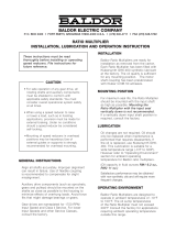
Figure 1 shows an example of a uid coupling and its major
components:
1. Input (motor shaft)
2. Output (driven shaft)
3. Fluid Coupling Unit
4. PARA-FLEX
®
PH Style Coupling
C
4
3
1
2
Figure 1 - KCP Fluid Coupling
WARNING: Because of the possible danger to person(s) or property from
accidents which may result from the improper use of products, it is
important that correct procedures be followed. Products must be used
in accordance with the engineering information specified in the catalog.
Proper installation, maintenance and operation procedures must be
observed. The instructions in the instruction manuals must be followed.
Inspections should be made as necessary to assure safe operation
under prevailing conditions. Proper guards and other suitable safety
devices or procedures, as may be desirable, or as may be specified in
safety codes should be provided, and are neither provided by Baldor
Electric Company, nor are the responsibility of Baldor Electric Company.
This unit and its associated equipment must be installed, adjusted and
maintained by qualified personnel who are familiar with the construction
and operation of all equipment in the system and the potential hazards
involved. When risks to persons or property may be involved, a holding
device must be an integral part of the driven equipment beyond the
speed reducer output shaft.
Instruction Manual
FLUID COUPLINGS
These instructions must be read thoroughly before installation or operation.
INSTALLATION / DISASSEMBLY
Model KCP/CKCP:
This coupling contains two sections consisting of a uid
coupling circuit (the CKCP contains a delay-ll chamber) and
a PARA-FLEX
®
coupling consisting of a PARA-FLEX PH high
speed element and PS assembly with TAPER-LOCK
®
bushing.
Install in the following sequence:
1. Set the Between Shaft Ends (B.S.E.) Dimension
for the Driver and Driven Equipment (Table 1).
Table 1
Size
Fluid Cplg.
Bore Size
BSE
KCP CKCP
11
1.625 6.26
–
1.875 5.64
12
1.625 6.21 8.87
1.875 5.59 8.25
13
1.875 7.46 9.82
2.125 6.83 9.19
2.375 6.21 8.57
15
2.125 9.86 12.54
2.375 9.24 11.92
2.875 7.86 10.54
17
2.375 10.11 13.26
2.875 8.73 11.88
3.375 8.11 11.26
19
2.375 10.11 13.26
2.875 8.73 11.88
3.375 8.11 11.26
21
2.375 11.79 15.73
3.375 10.54 14.48
24
2.875 11.79 15.73
3.375 10.54 14.48
3.875 10.29 14.23
NOTE: It is necessary to mark the BSE setting on the base
where the motor is mounted. The uid coupling unit is larger
than necessary between shaft ends and will need to be installed
after marking the setting and then moving the motor back to
allow for adequate room.
Coupling Styles:
KCP: 11-24
CKCP: 12-24
KCM: 7-34
CKCM: 12-34
Sheave Style:
KSD: 7-24

2
To install the KCP and CKCP Fluid Coupling, the motor shaft may need to be threaded. Values are given in Table 2.
Table 2
Size
Fluid Cplg.
Bore Size
Thread for installation
Housing Thread
for Dismounting
KCP minimum
rod length
CKCP minimum
rod length
KSD minimum
rod length
Mtr. Shaft
Hole Depth
Mtr. Shaft
Thread Depth
11
1.625
1/2–13
UNC
3/4–10
UNC
12 – – 2.25 1.5
1.875
12
1.625
1.875
12 14 – 2.25 1.5
13
1.875
7/8–9
UNC
12 15
–
2.25 1.5
2.125
2.375
15
2.125
3/4–10
UNC
15 17 20 2.25 1.75
2.375
2.875
17
2.375
2.875
7/8–9
UNC
1-1/4–7
UNC
15 18 23 2.5 2
3.375
19
2.375
15 18 23 2.5 2
2.875
3.375
21
2.375
17 21 25 2.5 2
3.375
24
2.875
17 21 27 2.5 2
3.375
3.875
2. Install Fluid Coupling:
Using the threaded bar as shown on Fig. 1, and using two
wrenches (hold wrench “A” and turn wrench “B” to draw the
coupling on to the motor shaft). For a good mounting, make
sure shafts are clean and without burrs, and lubricate the mating
surfaces with oil or antiseizing grease. Note: In case of hot
mounting (not recommended), do not reach a temperature above
195°F, or higher, which causes irrepairable damages to oil seals.
Tighten wrench “B” until the motor shaft end completely slides
onto coupling bore. Tighten the two setscrews on uid coupling
to lock it in place. Remove the threaded rod.
Important Notice: Always mount the KCP/CKCP coupling so
that the uid coupling is mounted on the input (motor) side.
3. Remove Fluid Coupling:
Back off locking screws.
Engage the dismounting threaded bar “C” (this is different from
mounting threaded bar) onto the back of the uid coupling (Figure
3). Continue with threading of the rod against the motor shaft.
This will cause the uid coupling body to slide off the motor shaft.
For KSD models provided with collet (sizes 7 through 13) proceed
as follows:
1. Remove hex head capscrew which retains the collet.
2. Tap the uid coupling body with a mallet. The uid coupling
should break free from the motor shaft.
3. Remove input shaft and coupling assembly with sheave from
motor shaft adapter. Remove sheave from sheave hub.
4. Assemble PARA-FLEX® Coupling to Fluid Coupling
Unit and Driven Equipment
Connect adapter plate (#4) to uid coupling unit. For KCP/CKCP
sizes 11 and 12, torque nuts attaching the adapter plate to 216
lb-in. For sizes 13, 15, 17, and 19, torque to 425 lb-in. For sizes
21 and 24, torque to 1,175 lb-in.
Before installing the exible element, slip bolt ring over ange and
rest it on the shaft. Remove clamp ring screws and internal clamp
ring. Place internal clamp ring inside the element and reassemble
to ange seating the bead of the element on the ange. Tighten
clamp ring screws alternately and evenly and torque to values
shown in column “A” in Table 3. On coupling sizes 15 through 24,
remove external clamp ring and rest it on shaft. Attach the spacer
hub to the clamp ring (external clamp ring for sizes 11-13 and
internal clamp ring for sizes 15-24). Torque to values in Table
3, column “D”. Install TAPER-LOCK bushing into ange. Turn
element on ange and reassemble clamp ring and screws.
Place bolt ring and screws in position. Tighten down screws
through the bolt ring and element through to the uid coupling
adapter plate. Tighten screws alternately and evenly and torque
to values shown in Table 3, column “B”.
Figure 2
C
Figure 3
4
5
6
8
7
1
3
2
KCP 11-13
4
5
6
1
8
7
3
KCP 15-24
Figure 4
1 FLEXIBLE ELEMENT
2 INTERNAL CLAMP RING
3 EXTERNAL CLAMP RING
4 FLUID COUPLING ADAPTER PLATE
5 BOLT RING
6 DISC ASSEMBLY SCREWS
7 CLAMP RING SCREWS
8 SPACER HUB
NOTES: FOR SIZES 11–13, IT IS NOT NECESSARY TO THREAD THE SHAFT.
If drilling and tapping the motor shaft, install threaded rod onto motor shaft, install motor shaft key, and follow mounting procedure as given in Step 2.
A
B

3
Table 3
Fluid Coupling
Size
Coupling
Size
Flange
Assembly
Size
Wrench Torque
(lb-in.)
A
(lb-in.)
B
(lb-in.)
D
E
Steel
Flanges
Iron
Flanges
11 KCP/CKCP PH 96 PX 80 290 290 300 300 0.025
12 KCP/CKCP PH 116 PX 100 480 480 360 300 0.030
13 KCP/CKCP PH 131 PX 110 480 480 420 300 0.035
15, 17, 19 KCP/CKCP PH 172 PX 140 1150 1080 600 720 0.045
21, 24 KCP/CKCP PH 192 PX 160 1150 2160 780 1296 0.050
5. Check Shaft Alignment of High Speed PARAFLEX
®
Coupling
BOLT RING
INDICATOR FOR
CHECKING PARALLEL
ALIGNMENT
INDICATOR FOR
CHECKING ANGULAR
ALIGNMENT
Although shafts may be perfectly aligned at installation, some
parallel and angular misalignment usually develops in usage
because of shifting of the driving and driven units. Check both
parallel and angular alignments by mounting indicators near the
O.D. of the ange as shown in the graphic above and rotate the
coupling through 360°. For a good installation, neither indicator
reading should exceed the value shown in Table 3, column “E”.
Both alignments should be rechecked after any repositioning.
INSTALLATION:
Model KSD:
This uid coupling is to be installed on the end of a drive shaft
with a sheave mounted on the uid coupling.
Sizes 7 through 13 are provided with an adapter collet. Install
in the following sequence:
1. Install key ush with end of drive shaft.
2. Install sheave to uid coupling hub, torque bushing capscrews
properly (see recommended bolt torques listed).
3. Install coupling assembly on drive shaft, (it may be necessary
to free the slotted adapter by pushing on loosened center
capscrew). Make sure slotted adapter does not ride up on any
radius or shoulder on the drive shaft. Note: Shaft must protrude
into slotted adapter 2.50 inches minimum.
4. Torque retaining collet capscrew.
CAUTION: The fluid coupling is installed on the end of a
shaft and it is essential that a guard be provided.
Sizes 15 through 24 are provided without collet. Install in the
following sequence:
1. To install KSD or CKSD uid coupling, the motor shaft may
need to be threaded. Values are given in Table 2.
2. Fit uid coupling on motor shaft by using a threaded bar as
shown on Figure 2 and using two wrenches (hold wrench “A”
and turn wrench “B” to draw the coupling on the motor shaft).
3. After tting, lock it down using the xing bolt. The xing bolt
thread must be the same as the thread for installation as given
in Table 2.
Table 4 - Recommended
Tightening Torque for Fixing Bolt
Size Torque (Max.)
¾–10 UNC 3000 lb-in.
7/8–9 UNC 4200 lb-in.
For good mounting, make sure shafts are clean
and without burrs, and lubricate the mating
surfaces with oil or antiseizing grease.
Figure 6
Figure 5
For REMOVAL: Refer to section 3 on page 2.
Model KCM, CKCM:
This coupling is a complete unit and is to be installed between
two halves of a double engagement gear tooth exible coupling.
The gear coupling halves need to have a shrouded bolt design,
not the exposed bolt version. Install in the following sequence:
1. Set between shaft spacing for driver and driven equipment per
chart below.
2. Install gear coupling half to each shaft.
3. Align shafts to within 0.030 total indicator reading.
4. Install uid coupling.
5. Torque coupling bolts to recommended installation torque as
shown in gear coupling instruction manual.
Figure 7
Table 6 - BSE Spacing for KCM/CKCM
Couplings
Size
KCM
Centre
Distance
CKCM
Center
Distance
Gear
Coupling
Size
7 5.63 – 201
8 5.83 – 201
9 7.09 – 201½
11 7.44 – 201½
12 7.91 10.55 201½
13 8.31 11.28 201½
15 10.04 13.15 202½
17 10.04 13.27 202½
19 10.04 13.27 202½
21 12.78 16.80 202½
24 12.78 16.80 202½
27 14.70 20.96 203½
29 15.84 22.10 203½
34 18.79 25.21 204
NOTE: The input side
ange on the uid
coupling has clearance
holes for the gear coupling
bolts and the output
side ange is threaded.
The uid coupling unit
is supplied with two
accessory kits. These
kits include bolts, nuts,
lockwashers, and gaskets.
Table 5 - Recommended Tightening
Torque for Bolt-On Sheaves
Qty Size Torque
12 M10 360 lb-in.
8 M14 720 lb-in.

World Headquarters
P.O. Box 2400, Fort Smith, AR 72902-2400 U.S.A., Ph: (1) 479.646.4711, Fax (1) 479.648.5792, International Fax (1) 479.648.5895
Dodge Product Support
6040 Ponders Court, Greenville, SC 29615-4617 U.S.A., Ph: (1) 864.297.4800, Fax: (1) 864.281.2433
www.baldor.com
© Baldor Electric Company
MN4051 (Replaces 499440)
All Rights Reserved. Printed in USA.
5/10 Printshop 500
*4051-0510*
OPERATION AND MAINTENANCE
1. Start motor several times to check the coupling
performance. Maximum temperature should not
exceed 195°F. For higher temperatures, contact
Baldor Electric, Dodge Engineering, Greenville,
SC.
High oil operating temperature can be caused by:
a) Insufcient oil lling.
b) Absorbed power is higher than the motor
rated power.
c) High ambient temperature.
d) Too frequent starts.
e) Long starting time.
f) Inadequate air ventilation to allow cooling
of the coupling. If coupling is operating in a
restricted space, adequate ventilation
apertures should be provided.
2. After the rst 20 days of operation, check the
lling (this must be carried out with cold oil).
Also, check the motor and driven machine’s
xing bolt.
3. Coupling is supplied with fusible plug at 290°F
(250°F, 350°F, or 390°F upon request). It is
suggested that these alternative fusible plugs
should be considered for belt conveyors,
crushers, mills, mixers, etc. where continual
overload conditions can occur. If the fusible plug
blows at regular intervals in normal service, then
re-check a) through f) above.
4. Oil should be replaced after 4,000 hours
operation.
FILLING INSTRUCTIONS
Series KCP, KSD, KCM:
Fluid couplings are not lled at the factory and thus a correct
lling procedure is necessary:
1. With the uid coupling mounted in a horizontal plane, turn the
coupling so the X mark which is cast into the housing is at the
top (maximum lling) which will ensure the ller/level plug item
13, is in the correct angular position as shown in Figure 8.
2. Fill with oil until it overows out of the ller hole. During lling,
rock the coupling gently on its axis to ensure all excess air is
vented from the circuit. Table 7 shows various oil quantities for
different llings. The lling procedure for these intermediate
lls is the same as outlined above, in each case the number
must be at the top of the unit.
3. To ensure no oil leaks from coupling during its operation, use
thread sealant on ller plug thread.
4. The different lling X-1-2-3-4 can be selected at the users
discretion to obtain a better performance from the coupling.
With X ll (maximum), the uid coupling will operate with
minimal slip and maximum efciency. The ratio starting
torque/nominal torque will be at maximum. By decreasing the
coupling’s oil lling (1-2-3-4), the contrary occurs.
5. High values of slip decrease the unit’s efciency and will
cause the oil to overheat.
6. Fluid recommendations are indicated in Table 9.
7. For vertical mounted applications, lls are indicated in Table 7.
Series CKCP, CKSD, CKCM:
Fluid coupling CK series (with delayed ll chamber) is used to
limit the starting torque/nominal torque ratio to 1.4. The starting
torque limitation can be obtained by reducing the oil quantity in
the working circuit (lling 2-3-4) without increasing the slip value
at rated speed. For each given size, see Table 7 or 8 for proper
lling position.
After lling the coupling, start the motor and check to make sure
the uid coupling operates properly. After approximately 100
hours, stop the motor and check the alignment and tightness of
the screws.
Table 7 - K... Series Oil Qty. U.S. Gal.
K… X 1 2 3 4
6 .132 .126 .120 .112 .103
7 .243 .227 .211 .192 .171
8 .338 .314 .290 .264 .237
9 .515 .480 .446 .409 .369
11 .727 .673 .620 .554 .488
12 1.083 1.023 .944 .858 .766
13 1.374 1.281 1.175 1.070 .951
15 2.020 1.889 1.743 1.585 1.426
17 3.090 2.879 2.642 2.404 2.166
19 3.750 3.513 3.249 2.959 2.642
21 5.020 4.702 4.332 3.963 3.566
24 7.500 7.001 6.499 5.970 5.416
27 11.090 10.300 9.511 8.850 8.322
29 14.533 13.47 12.417 11.624 10.964
Table 8 - CK … Series
Oil Qty. U.S. Gal.
CK … 2 3 4
11 .885 .805 .726
12 1.268 1.109 .951
13 1.532 1.373 1.241
15 2.272 2.034 1.690
17 3.593 3.381 3.091
19 4.306 4.015 3.698
21 6.076 5.627 5.099
24 8.243 7.556 6.869
27 13.21 12.28 11.36
29 16.64 15.58 14.26
Table 9 - Fluid Recommendation
Coupling Operating
Temperature
Above 160ºF Below 160ºF
SAE 10 W
Non-Detergent
SAE 5 W
Non-Detergent
For uids (F) with specitic gravity (S.G.)
Other than uid (G) with S.G. .88 at 60°F
HP. uid (F) = H.P. uid (G) ×
S.G. uid (G)
S.G. uid (F)
Figure 8
/