Page is loading ...

Model W1737/W1738
***IMPORTANT UPDATE***
Applies to Models Mfd. Since 1/14
and Owner's Manual Revised 11/09
Phone #: (360) 734-3482 • Tech Support: tech-support@shopfox.biz • Web: www.shopfox.biz
COPYRIGHT © MARCH, 2011 BY WOODSTOCK INTERNATIONAL, INC., REVISED JUNE, 2014 (TS)
WARNING: NO PORTION OF THIS MANUAL MAY BE REPRODUCED IN ANY SHAPE OR FORM WITHOUT
THE WRITTEN APPROVAL OF WOODSTOCK INTERNATIONAL, INC
We made the following changes to this machine since the manual was printed:
• Obtained CSA certification meeting CSA C22.2 #105-1953 and UL 987-7th standards.
• Changed contactors, overload relays, and fuses inside electrical cabinet.
• Changed machine wiring.
• Replaced oscillation diaphragm assembly (P/N 503) with an air cylinder (P/N 503V2).
Note: At the top of each page is a note that indicates which page it replaces or adds to in the original
manual. On the parts list, the new parts are designated with a “V2”.
Aside from the information contained in this update, all other content in the owner's manual MUST be
read and understood for your own safety. IMPORTANT: Keep this update with the owner's manual for
future reference. If you have any further questions, contact our Technical Support.
New W1738 440V Conversion Kit
READ THIS FIRST
NEW W1738 440V CONVERSION KIT PARTS
38V2 X1738038V2 440V CONVERSION KIT V2.03.11
3-1V2 X1738003-1V2 OL RELAY SCHN LR3D325 17-25A V2.03.11
11-1 X1738011-1 OL RELAY SCHN LR3D07 1.6-2.5A
2V2
3V3
12-1
38V2
3-1V2
12-1
39
11-1
4V2
#13934TS Printed in Taiwan

-2-
Model W1737/W1738 (Mfd. Since 1/14)
Indicates a potentially hazardous situation which, if not avoided,
MAY result in minor or moderate injury.
Indicates an imminently hazardous situation which, if not avoided,
WILL result in death or serious injury.
Indicates a potentially hazardous situation which, if not avoided,
COULD result in death or serious injury.
This symbol is used to alert the user to useful information about
proper operation of the equipment or a situation that may cause
damage to the machinery.
NOTICE
SAFETY
OWNER’S MANUAL.
Read and understand this
owner’s manual BEFORE using machine.
TRAINED OPERATORS ONLY.
Untrained operators
have a higher risk of being hurt or killed. Only
allow trained/supervised people to use this
machine. When machine is not being used,
disconnect power, remove switch keys, or
lock-out machine to prevent unauthorized
use—especially around children. Make
workshop kid proof!
DANGEROUS ENVIRONMENTS.
Do not use
machinery in areas that are wet, cluttered,
or have poor lighting. Operating machinery
in these areas greatly increases the risk of
accidents and injury.
MENTAL ALERTNESS REQUIRED.
Full mental
alertness is required for safe operation of
machinery. Never operate under the influence
of drugs or alcohol, when tired, or when
distracted.
ELECTRICAL EQUIPMENT INJURY RISKS. You can
be shocked, burned, or killed by touching live
electrical components or improperly grounded
machinery. To reduce this risk, only allow an
electrician or qualified service personnel to
do electrical installation or repair work, and
always disconnect power before accessing or
exposing electrical equipment.
DISCONNECT POWER FIRST. Always disconnect
machine from power supply BEFORE making
adjustments, changing tooling, or servicing
machine. This eliminates the risk of injury
from unintended startup or contact with live
electrical components.
EYE PROTECTION. Always wear ANSI-approved
safety glasses or a face shield when operating
or observing machinery to reduce the risk of
eye injury or blindness from flying particles.
Everyday eyeglasses are not approved safety
glasses.
Standard Machinery Safety Instructions
For Your Own Safety,
Read Manual Before Operating Machine
The purpose of safety symbols is to attract your attention to possible hazardous conditions. This
manual uses a series of symbols and signal words intended to convey the level of importance of the
safety messages. The progression of symbols is described below. Remember that safety messages by
themselves do not eliminate danger and are not a substitute for proper accident prevention mea-
sures—this responsibility is ultimately up to the operator!
SAFETY
Standard Machinery Safety Instructions
Replaces Page 6

-3-
Model W1737/W1738 (Mfd. Since 1/14)
WEARING PROPER APPAREL. Do not wear
clothing, apparel, or jewelry that can become
entangled in moving parts. Always tie back
or cover long hair. Wear non-slip footwear to
avoid accidental slips, which could cause loss
of workpiece control.
HAZARDOUS
DUST. Dust created while using
machinery may cause cancer, birth defects,
or long-term respiratory damage. Be aware of
dust hazards associated with each workpiece
material, and always wear a NIOSH-approved
respirator to reduce your risk.
HEARING PROTECTION.
Always wear hearing
protection when operating or observing
loud machinery. Extended exposure to this
noise without hearing protection can cause
permanent hearing loss.
REMOVE ADJUSTING TOOLS.
Tools left on
machinery can become dangerous projectiles
upon startup. Never leave chuck keys,
wrenches, or any other tools on machine.
Always verify removal before starting!
INTENDED USAGE.
Only use machine for its
intended purpose—never make modifications
without prior approval from Woodstock
International. Modifying machine or using
it differently than intended will void the
warranty and may result in malfunction or
mechanical failure that leads to serious
personal injury or death!
AWKWARD POSITIONS.
Keep proper footing and
balance at all times when operating machine.
Do not overreach! Avoid awkward hand
positions that make workpiece control difficult
or increase the risk of accidental injury.
CHILDREN & BYSTANDERS.
Keep children and
bystanders at a safe distance from the work
area. Stop using machine if they become a
distraction.
GUARDS & COVERS.
Guards and covers reduce
accidental contact with moving parts or flying
debris—make sure they are properly installed,
undamaged, and working correctly.
FORCING MACHINERY. Do not force machine. It
will do the job safer and better at the rate for
which it was designed.
NEVER STAND ON MACHINE. Serious injury may
occur if machine is tipped or if the cutting
tool is unintentionally contacted.
STABLE MACHINE. Unexpected movement during
operation greatly increases risk of injury or
loss of control. Before starting, verify machine
is stable and mobile base (if used) is locked.
USE RECOMMENDED ACCESSORIES. Consult
this owner’s manual or the manufacturer for
recommended accessories. Using improper
accessories will increase risk of serious injury.
UNATTENDED OPERATION. To reduce the risk
of accidental injury, turn machine OFF and
ensure all moving parts completely stop
before walking away. Never leave machine
running while unattended.
MAINTAIN WITH CARE. Follow all maintenance
instructions and lubrication schedules to
keep machine in good working condition. A
machine that is improperly maintained could
malfunction, leading to serious personal injury
or death.
CHECK DAMAGED PARTS. Regularly inspect
machine for any condition that may affect
safe operation. Immediately repair or replace
damaged or mis-adjusted parts before
operating machine.
MAINTAIN POWER CORDS. When disconnecting
cord-connected machines from power, grab
and pull the plug—NOT the cord. Pulling the
cord may damage the wires inside, resulting
in a short. Do not handle cord/plug with wet
hands. Avoid cord damage by keeping it away
from heated surfaces, high traffic areas, harsh
chemicals, and wet/damp locations.
EXPERIENCING DIFFICULTIES. If at any time
you experience difficulties performing the
intended operation, stop using the machine!
Contact Technical Support at (360) 734-3482.
Replaces Page 7

-4-
Model W1737/W1738 (Mfd. Since 1/14)
Additional Safety for Wide Belt Sanders
MINIMUM STOCK DIMENSION. To avoid kickback,
never sand workpieces below minimum
specifications listed in Data Sheet.
ADJUSTMENTS/MAINTENANCE. Make sure
machine is turned OFF, disconnected from
power and air, and all moving parts are
completely stopped before doing adjustments or
maintenance.
SANDING DUST. Sanding creates large amounts
of dust and flying chips that can lead to eye
injury or respiratory illness. Reduce risk of these
hazards by wearing approved eye and respiratory
protection when using sander.
DUST COLLECTION. Never operate without
adequate dust collection system in place and
running. Proper dust collection reduces dust in
work area, which decreases risk of long-term
respiratory damage, but it is not a substitute for
using a respirator.
Serious injury or death can occur from hands getting trapped between workpiece and conveyor
table, getting entangled in rotating parts inside machine, or lacerated by sanding drum.
Workpieces thrown by sander can strike nearby operators. Long-term respiratory damage can
occur from using sander without proper use of a respirator and an adequate dust collection
system. To minimize risk of getting hurt or killed, anyone operating machine MUST completely
heed hazards and warnings below.
FEEDING WORKPIECE. DO NOT place fingers
under bottom of workpiece while feeding it into
sander. Fingers can become pinched between
workpiece and conveyor.
ENTANGLEMENT HAZARDS. DO NOT wear loose
clothing, gloves, or jewelry, and tie back long
hair. Never reach inside operating machine or try
clearing jammed workpiece. Keep all guards in
place and secure, and all doors closed.
SANDING DRUM CONTACT. Rotating sandpaper
can remove a large amount of flesh in a few
seconds. Keep hands away from rotating sanding
drum(s) during operation. Never touch moving
sandpaper on purpose.
WORKPIECE KICKBACK. A workpiece can be
ejected out the front of sander at high rate of
speed, and hit operator or bystanders. Never
stand in-line with workpiece, never feed more
than one workpiece at a time, and always adjust
pressure rollers below sanding roller.
Replaces Page 8

-5-
Model W1737/W1738 (Mfd. Since 1/14)
Replaces Page 10
Availability
Before installing the machine, consider the availability
and proximity of the required power supply circuit. If an
existing circuit does not meet the requirements for this
machine, a new circuit must be installed. To minimize
the risk of electrocution, fire, or equipment damage,
installation work and electrical wiring must be done by
a qualified electrician in accordance with all applicable
codes and standards.
Full-Load Current Rating
The full-load current rating is the amperage a machine
draws at 100% of the rated output power. On machines
with multiple motors, this is the amperage drawn by the
largest motor or sum of all motors and electrical devices
that might operate at one time during normal operations.
W1737 Full-Load Current Rating at 230V ...... 57 Amps
W1738 Full-Load Current Rating at 230V ... 39.4 Amps
W1738 Full-Load Current Rating at 460V ... 19.7 Amps
The full-load current is not the maximum amount of amps
that the machine will draw. If the machine is overloaded,
it will draw additional amps beyond the full-load rating.
If the machine is overloaded for a sufficient length of
time, damage, overheating, or fire may result—especially
if connected to an undersized circuit. To reduce the
risk of these hazards, avoid overloading the machine
during operation and make sure it is connected to a
power supply circuit that meets the requirements in the
following section.
Electrocution, fire, or equipment
damage may occur if machine is not
correctly grounded and connected to
the power supply.
For your own safety and protection of
property, consult a qualified electrician
if you are unsure about wiring practices
or electrical codes in your area.
ELECTRICAL
A power supply circuit includes all electrical equipment
between the breaker box or fuse panel in the building
and the machine. The power supply circuit used for
this machine must be sized to safely handle the full-
load current drawn from the machine for an extended
period of time. (If this machine is connected to a circuit
protected by fuses, use a time delay fuse marked D.)
Circuit Information

-6-
Model W1737/W1738 (Mfd. Since 1/14)
Note: The circuit requirements listed in this
manual apply to a dedicated circuit—where
only one machine will be running at a
time. If this machine will be connected to
a shared circuit where multiple machines
will be running at the same time, consult
a qualified electrician to ensure that the
circuit is properly sized for safe operation.
Serious injury could occur if you con-
nect the machine to power before
completing the setup process. DO NOT
connect to power until instructed later
in this manual.
Power
Source
Locking
Disconnect Switch
Machine
Ground Ground
ConduitConduit
Figure 1. Typical setup of a permanently
connected machine.
Extension Cords
W1737 Circuit Requirements for 230V
Nominal Voltage ......................... 220V, 230V, 240V
Cycle ........................................................60 Hz
Phase .............................................. Single-Phase
Circuit Rating ......................................... 70 Amps
W1738 Circuit Requirements for 230V
Nominal Voltage ......................... 220V, 230V, 240V
Cycle ........................................................60 Hz
Phase .................................................... 3-Phase
Minimum Circuit Size ............................... 50 Amps
W1738 Circuit Requirements for 460V
Nominal Voltage ......................... 440V, 460V, 480V
Cycle ........................................................60 Hz
Phase .................................................... 3-Phase
Minimum Circuit Size ............................... 30 Amps
This machine must be permanently connected the power
supply for 460V operation. A disconnecting means, such
as a locking switch (see the figure to the right), must
be provided to allow the machine to be disconnected
(isolated) from the power supply when required. This
installation must be performed by a qualified electrician
in accordance with all applicable electrical codes and
ordinances.
Grounding Instructions
This machine must be grounded! In the event of a
malfunction or breakdown, grounding provides a path of
least resistance for electrical current to reduce the risk of
electric shock. A permanently connect machine must be
connected to a grounded metal permanent wiring system;
or to a system having an equipment-grounding conductor.
All grounds must be verified and rated for the electrical
requirements of the machine. Improper grounding can
increase the risk of electric shock!
In Addition to Page 10
This machine is prewired to operate on a 230V power
supply circuit that has a verified ground and meets the
following requirements:
This machine is prewired to operate on a 230V power
supply circuit that has a verified ground and meets the
following requirements:
This machine can be converted to operate on a 460V
power supply (refer to Voltage Conversion later in this
section). The intended 460V circuit must have a verified
ground and meet the following requirements:
Since this machine must be permanently
connected to the power supply, an
extension cord cannot be used.

-7-
Model W1737/W1738 (Mfd. Since 1/14)
440V Conversion (W1738)
This machine is prewired for 230V 3-phase power but has
the capability of operating on 460V power with a minor
conversion. The conversion consists of replacing two
overload relays and rewiring each of the three motors.
All wiring changes must be inspected by a qualified
electrician or service personnel before the machine is
connected to the power source.
Contact your local Shop Fox dealer to purchase the
440V conversion kit (P/N X1738038V2) that includes the
necessary two overload relays.
To convert Model W1738 to 460V operation, do these
steps:
1. DISCONNECT SANDER FROM POWER!
2. Open electrical cabinet on back of machine.
3. Remove wire labeled "1" at 220V terminal of trans-
former and connect it to 440V terminal (see Figures
6–7).
4. Replace thermal overload relays, as shown in
Figure 6.
5. Set LR3D325 amperage dial to 18A and LR3D07
amperage dial to 1.7A.
6. Re-wire sanding, conveyor, and table elevation
motors as shown in wiring diagrams on Page 34 of
owner's manual.
Figure 6. Locations of thermal overload
relays and transformer.
Replace with
LR3D325
Replace with
LR3D07
Transformer
Transformer
200V 220V0V0V 440V
0
2
3
1
Figure 7. W1738 transformer re-wired for
460V operation.
Replaces Page 11

-8-
Model W1737/W1738 (Mfd. Since 1/14)
Replaces Page 21
Jet Air Flow
The air jet located at the air fork sends a stream of
air across the air fork and into the air stream receiver
(see Figure 23). As soon as the sanding belt obstructs
this stream of air, a piston changes the direction of belt
movement to the left. Your goal is to adjust this stream
of air so the system uses the least amount of air and yet
the machine still oscillates consistently.
To adjust the jet air flow, do these steps:
1. TURN OFF and LOCK your master power switch.
2. Adjust the air regulator to 70 PSI.
3. Open both upper access doors on the sander, loosen
the sanding belt tension, and slide the belt so the
air stream is unobstructed.
4. Loosen the jam nut and turn the jet adjustment
knob (Figure 24) clockwise until the air stream is
reduced to a minimum.
5. Turn the jet adjustment knob counterclockwise, and
use a piece of cardboard to alternately block and
unblock the air stream until the upper drum just
begins to react and move left and right.
6. Turn the jet adjustment knob counterclockwise an
additional
1
⁄2 turn and tighten the jam nut.
7. Complete Belt Tracking on Page 22.
Figure 23. Air Jet and air fork assembly.
Figure 24. Air Stream adjustment knob.
Air Stream
Receiver
Air Fork
Air Jet
Air Stream
Adjustment
Knob
Lock
Lever
Height
Lever
Scale and
Pointer
Using the Platen
The platen controls (Figure 25) on your sander allow for
three basic types of sanding. Note: The platen scale is
broken down in millimeter increments, and is for only
reduced-platen sanding depth positions. For aggressive
sanding, retract the platen to the Platen Up position,
adjust the table, and let the drums make the deep cut.
Platen Up — The platen is above the level of the sanding
rollers, so the front roller removes large amounts of
material quickly, but leaves a rough finish.
Platen Even — The platen is even with the sanding
rollers, so the rollers work together with the platen to
produce intermediate/final finishing.
Platen Down — The platen is 0.2mm below the sanding
rollers, so the platen gives a smooth and feathered
finish. Avoid lowering the platen more than 0.2mm below
the sanding belt rollers.
Figure 25. Platen controls.

-9-
Model W1737/W1738 (Mfd. Since 1/14)
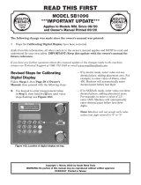
W1737 & W1738 Control Panel Wiring
Replaces Page 35
AMP DRAW
METER
SANDING MOTOR
START
BUTTON
SANDING MOTOR
STOP
BUTTON
DIGITAL
PANEL
FEED MOTOR
START
BUTTON
FEED MOTOR
STOP
BUTTON
EMERGENCY
SHUT-OFF
BUTTON
POWER
LAMP

-10-
Model W1737/W1738 (Mfd. Since 1/14)
W1737 General Wiring Diagram
Replaces Page 36

-11-
Model W1737/W1738 (Mfd. Since 1/14)
Replaces Page 37
W1738 General Wiring Diagram

-12-
Model W1737/W1738 (Mfd. Since 1/14)
W1738 Electrical Cabinet Wiring
Replaces Page 39

-13-
Model W1737/W1738 (Mfd. Since 1/14)
Replaces Page 40
W1737 Electrical Box Component Locations
Sanding
Motor
Contactor
Feed Motor
Contactor
Amp Meter
Current Sensor
Emergency Brake
Contactor
Sanding Belt
Overload Relay
4 Amp
Fuses
Power Supply
Terminal Bar
UP/DOWN Table Motor
Contactors
Feed Motor
Overload Relay

-14-
Model W1737/W1738 (Mfd. Since 1/14)
W1737 Electrical Cabinet Wiring
Replaces Page 41

-15-
Model W1737/W1738 (Mfd. Since 1/14)
Electrical Parts
Replaces Page 42
6
7
17
15
15
16
37
31
34
8
14V2
36
33
2V2
12
12-1
12
4V2
5V2 (W1738 Only)
5V2 (W1737 Only)
11-1 (W1738 440V
Conversion Only)
3V3
3-1V2 (W1738 440V
Conversion Only)
11
1
24
21
18
35
20
26
23
10
31
9
39
25
27V2 (W1738 Only)
38 (W1737 Only)

-16-
Model W1737/W1738 (Mfd. Since 1/14)
Electrical Parts List
Replaces Page 43
REF PART # DESCRIPTION REF PART # DESCRIPTION
1 X1737001 CURRENT SENSOR 14V2 X1738014V2 TERMINAL BAR V2.10.09 (W1738)
2V2 X1737002V2 CONTACTOR SCHN LC1D50A V2.03.11 15 X1737015 PU CONNECTOR 1/2
(W1737) 16 X1737016 PU CONNECTOR 3/4
2V2 X1738002V2 CONTACTOR SCHN LC1D40A V2.03.11 17 X1737017 CABLE CONNECTOR 1"
(W1738) 18 X1737018 DIGITAL AMP METER
3V3 X1738003V3 OL RELAY SCHN LRD340 30-40A 20 X1737020 START SWITCH
V3.04.13 (W1738) 21 X1737021 STOP SWITCH
4V2 X1737004V2 FUSE 4A 10 X 38MM V2.03.11 23 X1737023 POWER INDICATION LIGHT
5V2
X1737005V2
TERMINAL BLOCK V2.10.09 (W1737) 24 X1737024 EMERGENCY STOP SWITCH
5V2
X1738005V2
TERMINAL BLOCK V2.10.09 (W1738) 25 X1737025 WIRE COLUMN
6 X1737006 ELECTRICAL CONTROL BOX 26 X1737026 COMPUTER
7 X1737007 HINGE 27V2 X1738027V2 TRANSFORMER 3PH V2.10.09 (W1738)
8 X1737008 DOOR 31 XPLW02 LOCK WASHER 1/4
9 X1737009 BASE PLATE 33 XPN05 HEX NUT 1/4-20
10 X1737010 CONTROL PANEL 34 XPS04 PHLP HD SCR 1/4-20 X 1/2
11 X1737011 OL RELAY SCHN LR3D12 5.5-8A (W1737) 35 XPS07M PHLP HD SCR M4-.7 X 8
11 X1738011 OL RELAY SCHN LR3D08 2.5-4A (W1738) 36 XPS51M PHLP HD SCR M4-.7 X 30
12 X1737012 CONTACTOR SCHN LC1D09 37 XPW06 FLAT WASHER 1/4
12-1 X1737012-1 CONTACTOR SCHN LC1D09 W/LOCK 38 X1689624 OL RELAY SCHN LT47 5-60A (W1737)
14V2 X1737014V2 TERMINAL BAR V2.10.09 (W1737) 39 X1737039 FUSE HOLDER SCHN DF101 10 X 38MM
W1738 440V CONVERSION KIT
3-1V2 X1738003-1V2 OL RELAY SCHN LR3D325 17-25A
V2.03.11 (W1738)
11-1 X1738011-1 OL RELAY SCHN LR3D07 1.6-2.5A
(W1738)
38V2 X1738038V2
440V CONVERSION KIT V2.03.11

-17-
Model W1737/W1738 (Mfd. Since 1/14)
New Upper Roller Air Cylinder
562
569
567
503V2
513
568
Previous Version Oscillation
Diaphragm Assembly (P/N 503)
New Version Air Cylinder (P/N 503V2)
REF PART # DESCRIPTION REF PART # DESCRIPTION
503V2 X1737503V2 OSCILLATION AIR CYLINDER V2.01.14 567 X1737567 HEX BOLT 5/16-18 X 1-1/2
513 X1737513 LOCK WASHER 5/16 568 X1737568 HEX NUT 5/16-18
562 X1737562 UNIVERSAL JOINT FORK 569 X1737569 CONNECTOR 1/4N X 1/8T X 90 DEG
In Addition to Pages 52–53

-18-
Model W1737/W1738 (Mfd. Since 1/14)
Air System Parts
Replaces Page 54
IN
616
617
618
619
620
621
615
626
627
628
629
630
632
633
625
627
634
603
601
602
603
604
605
606
636
608
609
610
611
612
613
614
632
607
622
624

-19-
Model W1737/W1738 (Mfd. Since 1/14)
Air System Parts List
REF PART # DESCRIPTION REF PART # DESCRIPTION
601 X1737601 AIR SWITCH 1/8 618 X1737618 CONNECTOR 5/16N X 1/4T
602 X1737602 CONNECTOR 1/4N X 1/8T 619 X1737619 8MM FLEXIBLE HOSE
603 X1737603 CONNECTOR 1/4N X 1/8T 90º 620 X1737620 AIR SWITCH 1/4
604 X1737604 BUFFER (BRONZE) 621 X1737621 ELBOW 1/4T x 1/4T 90º
605 X1737605 CONNECTOR 5/16N X 1/8T 90º 622 X1737622 SOLENOID VALVE
606 X1737606 8MM FLEXIBLE HOSE 624 X1737624 THROTTLE VALVE 1/8
607 X1737607 8MM FLEXIBLE HOSE 625 X1737625 CONNECTOR 5/16N X 1/4T
608 X1737608 6MM FLEXIBLE HOSE 626 X1737626 MANIFOLD
609 X1737609 6MM FLEXIBLE HOSE 627 X1737627 CONNECTOR 1/4N X 1/4T
610 X1737610 6MM FLEXIBLE HOSE 628 X1737628 BRONZE ELBOW 1/4T X 1/8T 90º
611 X1737611 6MM FLEXIBLE HOSE 629 X1737629 CONNECTOR 1/4N X 1/8T 90º
612 X1737612 6MM FLEXIBLE HOSE 630 X1737630 CONNECTOR 1/4N X 1/8T 90º
613 X1737613 6MM FLEXIBLE HOSE 632 X1737632 CONNECTOR 1/4N X 1/8T
614 X1737614 6MM FLEXIBLE HOSE 633 X1737633 BRONZE CONNECTOR 1/4N
615 XPS22 PHLP HD SCR 10-24 x 5/8 634 X1737634 CONNECTOR 1/4N X 3/8T
616 X1737616 PRESSURE REGULATOR 636 X1737636 8MM FLEXIBLE HOSE
617 X1737617 PSI GAUGE
Replaces Page 55

-20-
Model W1737/W1738 (Mfd. Since 1/14)
717
759
760
712
700
710
758
728
701
701
729
703
757
714
709
706
742
736
719
702
741
743
744
738
740
725
737
739
702
719
736
742
706
722
726
747
749
748
707
727
711
751
752
754
755
745
746
753
716
750
725
723
723
756
732
705
731
733
724
735
712
70 8
734
704
730
718
720
715
Replaces Page 56
Sanding Drum and Roller Parts
/