Specifications
Inventory
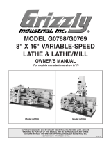
Figure 1
MODEL H8371
POWER FEED
FOR KNEE MILLS
INSTRUCTIONS
&
'K'
(
)
*
Figure 1.
WARNING: NO PORTION OF THIS MANUAL MAY BE REPRODUCED IN ANY SHAPE
OR FORM WITHOUT THE WRITTEN APPROVAL OF GRIZZLY INDUSTRIAL, INC.
If you need help with your new power feed, call
our Tech Support at: (570) 546-9663.
Bolt Bag Inventory Qty
REF PART # DESCRIPTION
1 PH8371001 MOUNTING BRACKET
2V2 PH8371002V2 PWR FEED & LIMIT SWITCH ASSY V2.07.11
3 PH8371003 COMPLETE BOLT BAG
4 PH8371004 LIMIT STOP ASSEMBLY
5 PH8371005 BEVEL GEAR BRASS
Be sure there is enough running clearance
between the table, spindle, vise/clamps, or
jigs before turning the power feed ON. Be
aware that all of these objects represent
potential pinch points.

6
7
8
9
:
;
<
=
Figure 2.
A. Limit Switch:
B. Limit Stop:
C. Rapid Movement Button:
D. Direction Lever:
E. Speed Dial:
F. Reset Button:
G. ON/OFF Switch:
H. Power Lamp:
ON
Functional Overview
Figure 2
Installation
1.
Note: During the next step, take care not to
misplace the leadscrew keys.
2.
3.
Step 4
Using the Mounting BracketPage 4
4.
Figure 3
Figure 3.
Note: Use the spacers provided where nec-
essary to ensure that the parts installed on
the leadscrew stay snug up against one
another.

5.
Note: If the threaded holes in the mill do not
align with the holes provided in the power
feed unit, drill and tap holes in the mill as
necessary to properly secure the unit to the
mill.
6.
7.
Figure 4
Note: Make sure that the teeth of the bevel
gear and drive gear mesh properly.
Figure 4.
8.
Electrocution or fire could
result if machine is not
grounded and installed in
compliance with electrical
codes. Compliance MUST
be verified by a qualified
electrician!
10.
Figure 5
11. OFF
Figure 5.
9.
Figure 5

Using the Mounting Bracket
1.
Figure 6
Figure 7.
Figure 6.
2.
Note: Use the spacers provided where nec-
essary to ensure that the parts installed on
the leadscrew stay snug up against one
another.
3.
Figure 7
Maintenance
To clean and lubricate the power feed gear-
ing:
1.
2.
3.
4.
5.
6.
4. Step 6Page 3
/