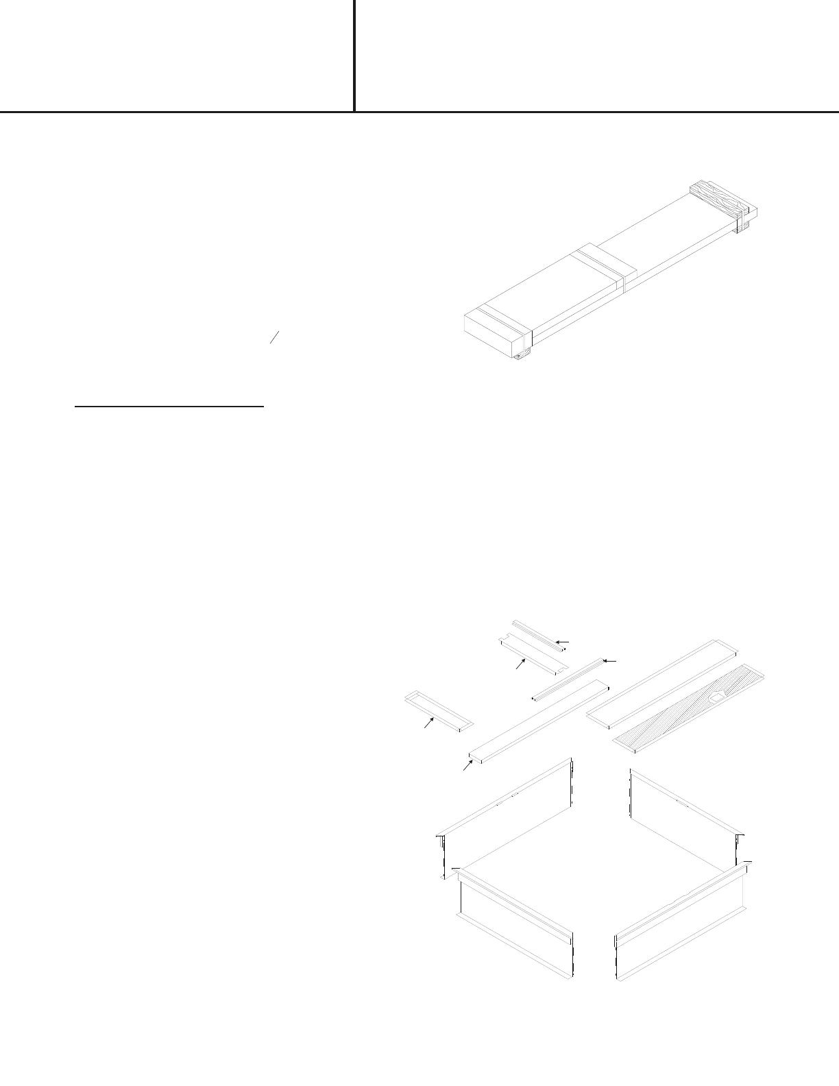
Unbranded Q6SD Installation guide

Type
Installation guide
Step 1:
Curb Package is shown as shipped with easy to
identify part numbers on all sides. Cut shipping
bands and remove Hardware, Gasket Material,
4 Duct Supports, and 3 Insulated Pans.
Step 2:
Layout the curb pieces before assembly to
insure that all the necessary pieces are
included.
(B)
(C)
(E)
(A)
(G)
(A)
(F)
(H)
(D)
(B)
(G)
1) 2 ea. Curb Long Sides - 49 ½" Long (A)
2) 2 ea. Curb Short Sides - 41 ½" Long (B)
3) 1 ea. Horizontal Duct Support - 46 ½" Long (C)
4) 1 ea. Vertical Duct Support - 21" Long (D)
5) 1 ea. Vertical Hat Section - 19" Long (E)
6) 1 ea. Horizontal Hat Section - 25" Long (F)
7) 2 ea. Insulated Pan - 46 ½" Long (G)
8) 1 ea. Insulated Pan - 21” Long (H)
9) 1 ea. Hardware Package Includes:
4 ea. "Hinge" Pins
3
16
"
12 ea. Hex Washers screws #10 x ½"
10) 2 ea. Gasket ¾" x 1 ¼" x 14' (28 ft. total)
U.S. PATENT 5148647
FORM# 593A- 0514 (593A- 0808)
INSTALLATION INSTRUCTIONS FOR
547830A / 547831A / 547850A / 547851A
ROOF CURBS USED WITH R4GM-072, P6SD/P8SE,
Q6SD/Q8SE, R6G(D,F,I), R8G(D,E), R8HE 024-060 UNITS
INSTALLATION
INSTRUCTIONS
This Roof Curb is NRCA approved and is constructed of 18 gauge galvanized steel with a full perimeter 1" x 4" wood nailer
strip. The curb is designed to be used with the Cooling, Gas Electric, and Heat Pump Models. The curb is shipped with the
following parts, See Figure 2:
Fig ure 1
Fig ure 2
I
mportant! Notice to Installer
If setting this curb for use with Nortek Global HVAC 95% AFUE R8HE/PPG3HE Series condensing style package
gas/electric unit, routing and securement of the gas heat exchanger condensate drain line must be determined
and installed prior to setting the unit on the curb.
It is recommended to drill a 1.00”-1.25” diameter hole through the roof below the rectangular opening located in outer close
off panel (G), approximately 15” in from the short side of the curb and 1”-2” in from the long side of the curb. (See Figure 7)
If drilling a hole is not an option, routing of the condensate drain hose over to the duct passage opening with enough slope
is acceptable as long as drain line is secured to curb and duct, ensuring no kinks or traps can form between the collector
box drain or interior of the building. Leave a minimum of 24” drain line extending out the top of front close off panel (G) for
passage through unit bottom and connection to unit drain when unit is being set. See unit or Condensate/Vent Drain Kit
(P/N-922485) instructions for completion of the drain connection. It is recommended no non-serviceable connections are
introduced in the drain line between unit drain connection and an accessible area within the building interior. Securement
of the drain line to the inside surface of the roof curb is acceptable and should be made in the wood nailer area ( top 3.5”) to
avoid possible leaks or penetrations to roofing materials.
1.
Duct Support flange goes in slot on
curb. Screw Brace to curb.
Brace inter-locks
with curb.
Step 4:
After the four corners are assembled; the curb should be checked to be sure it is in "square". Do this by measuring
diagonally from each opposite corner as shown in Figure 5. The two measurements should be the same for each direction.
Step 3:
Corner Assembly: Align each curb side as shown in Figure 3. Using a hammer, drive the curb "hinge" pin down until the
top of the pin is below the top of the curb as shown in Figure 4.
DETAILS
2.
Duct Support flange goes in slot on
pan or other brace. Screw brace
together.
Brace inter-locks
with pan or other
brace.
3.
Tab rests on top of curb for
added support.
Duct Support is supported by "tabs".
Screw pan to curb.
Figure 5
INSTALLATION INSTRUCTIONS FOR
547830A / 547831A / 547850A / 547851A
ROOF CURBS USED WITH R4GM-072, P6SD/P8SE,
Q6SD/Q8SE, R6G(D,F,I), R8G(D,E), R8HE 024-060 UNITS
Figure 6
22
21
1
2
FLUSH WITH EDGE
INSTALLATION
INSTRUCTIONS
HINGE
Fig ure 4
Fig ure 3
HINGE PIN
TAPERED END
CURB SIDE
Note:
Duct Sup ports can be lo cated on ei ther end de pend ing
on in di vid ual ap pli ca tions.
Step 5:
Install the duct horizontal support (C) as shown with
opening over the desired duct location as shown in Figure
7.
Step 6:
Install the vertical duct support (D) as shown in Figure 7.
Step 7:
Install the vertical duct support (E) and horizontal duct
support (F) on top of vertical duct support (D) and
horizontal duct support (C) respectively as shown in Figure
6.
Step 8:
Install the insulated pans (G) and (H) as shown in Figure 7.
Note:
If installing this curb for use with Nortek Global HVAC
R8HE Series
4 ½
46 ½
38 ½
41 ½
19
19
4
Fig ure 7
INSTALLATION INSTRUCTIONS FOR
547830A / 547831A / 547850A / 547851A
ROOF CURBS USED WITH R4GM-072, P6SD/P8SE,
Q6SD/Q8SE, R6G(D,F,I), R8G(D,E), R8HE 024-060 UNITS
(H)
(C)
DE TAIL #3
INSTALLATION
INSTRUCTIONS
GAS KET PLACE MENT
(BOLD BLACK LINES)
(D)
Gasket Layout
For optimum system performance
all cracks and seams should be
sealed with approved methods and
materials
condensing style package gas/electric unit, cut and
remove the insulation covering the 2” x 3” condensate
drain passage in outer panel (G) only. Before installing
inner panel (G) ensure there is enough slope and there are
no kinks or high spots that could trap water in the line prior
to entering the warmer interior of the building where a drain
trap is REQUIRED.
Step 9:
If the curb is being assembled and moved to another
location, attach the duct supports as shown in "Details".
Step 10:
Install 18 ½" x 18 ½" duct and secure to the curb with
screws or rivets.
Step 11:
Place the ¾" x 1 ¼" Gasket on all of the top edges of the
Roof Curb, including the duct supports. See Figure 7.
NOTE:
Figure 7 is shown without parts (E) and (F)
DETAIL #2
Duct Sizes Are:
Return 18 ½" x 18 ½"
Supply 18 ½" x 18 ½"
Roof Opening: (Shaded Area)
46 ½" Long x 19" Wide
SUP PLY
RETURN
4 ½
49 ½
19
*A
7
3
8
7
3
8
DETAIL #1
24" MINIMUM LENGTH OF
½" ID HOSE ABOVE TOP
OF CURB REQUIRED FOR
CONNECTION TO R8HE
SERIES UNITS
DI MEN SIONS
MODEL# *A
547830A 8
547831A 14
547850A 18
547851A 24
(G)
CURB FRAME
WOOD NAILER
COUNTER FLASHING
(FIELD SUPPLIED)
ROOFING FELT
(FIELD SUPPLIED)
RIGID INSULATION
(FIELD SUPPLIED)
ROOF INSTRUCTIONS
NEICRB06
SUPERSEDES 07-27-10
MAY 16, 2014
INSTALLATION INSTRUCTIONS FOR
547830A / 547831A / 547850A / 547851A
ROOF CURBS USED WITH R4GM-072, P6SD/P8SE,
Q6SD/Q8SE, R6G(D,F,I), R8G(D,E), R8HE 024-060 UNITS
INSTALLATION
INSTRUCTIONS
CANT STRIP
(FIELD SUPPLIED)
© Nortek Global HVAC
, LLC 2015. All Rights Reserved.
  • Page 1 1
  • Page 2 2
  • Page 3 3
  • Page 4 4

Unbranded Q6SD Installation guide

Type
Installation guide

Ask a question and I''ll find the answer in the document

Finding information in a document is now easier with AI