ForYourSafety...................................... 2
GrillServiceCenter................................... 2
ProductRecordInformation............................ 2
SafetySymbols...................................... 2
InstallationSafetyPrecautions.......................... 2
KenmoreEliteGrillWarranty........................... 3
UseandCare.................................... 4-10
PartsList.......................................... 11
PartsDiagram...................................... 12
Assembly....................................... 13-23
Troubleshooting.................................. 24-26
RepairProtection Agreements
Congratulations on making a smart purchase. Your new
Kenmore® productis designed and manufacturedfor years of
dependable operation. But like all products, it may require repair
from time to time. That'swhen having a Repair Protection
Agreement cansave you money and aggravation.
Here's what the Repair Protection Agreement* includes:
[] Expert service by our 10,000professional repair specialists
[] Unlimited service and no charge for parts and labor on all
covered repairs
[] Product replacement up to $1500 if your covered product
can't befixed
[] Discount of 10%from regular price of service and related
installed parts notcovered by the agreement; also, 10% off
regular price of preventive maintenance check
[] Fast help by phone - we call it Rapid Resolution -
phone support from a Sears representative.Think of us
as a "talkingowner's manual."
Once you purchase the Repair ProtectionAgreement, a
simple phone call is all that ittakes for you to schedule service.
You can call anytime day or night, or schedule a service
appointment online.
The Repair ProtectionAgreement is a risk-free purchase. If
you cancel for any reason during the product warranty period,
wewilt provide a full refund.Or, a prorated refundanytime after
the product warranty period expires. Purchase your Repair
ProtectionAgreement today!
Some limitations and exclusions apply. For prices and
additional information in the U.S.A. call 1-800-827-6655.
*Coverage in Canada varies on some items. For full details
call Sears Canada at 1-800-361-6665.
Sears Installation Service
For Sears professional installation of home appliances, garage
door openers, water heaters, and other major home items, in the
U.S.A. or Canada call 1-800-4-MY-HOME®.
KENMORE GRILL WARRANTY
One Year Full Warranty on Kenmore Grill
If this grill fails due to a defect in material or workmanship
within one year from the date of purchase, call 1-800-4-MY-
HOME% arrange for free repair (or replacement if repair
proves impossible).
Ten-Year Limited Warranty on Burners
Forten years from the date of purchase, any burner that
ruststhrough wilt be replaced free of charge.After the first
yearfrom the date of purchase,you payfor labor ifyou wish
to have it installed.
All warranty coverage excludes ignitor batteries and grill part
paint loss, discoloration or surface rusting,which are either
expendable parts that can wear out from normal usewithin
thewarranty period, or are conditions that can be the result
of normal use, accident or improper maintenance.
All warranty coverage is void if this grill is ever used for
commercial or rental purposes.
All warranty coverage applies only if this grill is used in the
United States.
This warranty gives you specific legal rights, and you may
also have other rights which vary from state to state.
Sears, Roebuck and Co., Hoffman Estates, IL 60179
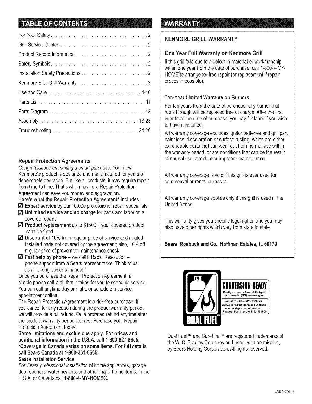
CONVERSION-READY
Easily converts from (LP) liquid
propane to (NG) natural gas
Contact I-8OO4-MY-HOME or
_parts to purchase
a natura_ gas conversion kff,
Request Part number 41&4584609
Dual FuerrMand SureFireTM are registered trademarksof
the W. C. Bradley Company and used, with permission,
by Sears Holding Corporation.All rights reserved.
464261709• 3


