Page is loading ...

1"1"1
®
to the Expertg
Installation Instructions
¸¸ ii =iL } ! /(
40QNC, QNQ Unit
NOTE: Read the entire instruction manual before starting the
installation,
UNIT OPERATION AND SAFETY HAZARD
Failure to follow this warning could result in personal injury or
equipment damage.
Puron refrigerant systems operate at higher pressures than
standard R-22 systems. To avoid damage to the unit or
possible personal injury, do not use R-22 service equipment or
components on Puron refrigerant equipment.
SAFETY CONSIDERATIONS
Improper installation, adjustment, alteration, service, maintenance,
or use can cause explosion, fire, electrical shock, or other
conditions which may cause death, personal injury, or property
damage. Consult a qualified installer, service agency, or your
distributor or branch for information or assistance. The qualified
installer or agency must use factory-authorized kits or accessories
when modifying this product. Refer to the individual instructions
packaged with the kits or accessories when installing.
Follow all safety codes. Wear safety glasses, protective clothing,
and work gloves. Use quenching cloth for brazing operations.
Have fire extinguisher available. Read these instructions
thoroughly and follow all warnings or cautions included in
literature and attached to the unit. Consult local building codes and
current editions of the National Electrical Code ( NEC ) NFPA 70.
In Canada, refer to current editions of the Canadian electrical code
CSA 22.1.
Recognize safety information. This is the safety-alert symbol/k
When you see this symbol on the unit and in instructions or
manuals, be alert to the potential for personal injury. Understand
these signal words; DANGER, WARNING, and CAUTION. These
words are used with the safety-alert symbol. DANGER identifies
the most serious hazards which will result in severe personal injury
or death. WARNING signifies hazards which could result in
personal injury or death. CAUTION is used to identify unsafe
practices which would result in minor personal injury or product
and property damage. NOTE is used to highlight suggestions
which will result in enhanced installation, reliability, or operation.
ELECTRICALSHOCK HAZARD
Failure to follow this warning could result in personal
injury or death.
Before installing, modifying, or servicing system, main
electrical disconnect switch must be in the OFF
position. There may be more than 1 disconnect switch.
Lock out and tag switch with a suitable warning label.
PERSONAL INJURY AND EQUIPMENT DAMAGE
HAZARD
Failure to follow this caution may result in personal injury
and / or equipment damage.
DO NOT operate the unit without a filter or with grille
removed.

DIMENSIONS - INDOOR
.I
W H D Operating Weight
Model Size
In. (mm) In. (mm) In. (mm) Ib (kg)
18k 42.5 (1080) 11.6 (295) 7.9 (201) 61 (14.1)
24k 42.5 (1080) 11.6 (295) 7.9 (201) 61 (14.1)
60k 57.5 (1461) 13.4 (340) 9.5 (241) 51 (28.2)
36k 57.5 (1461) 13.4 (340) 9.5 (241) 51 (23.2)
Fig. 1 - 40QNC,QNQ Unit Dimensions
A08433
DIMENSIONS - OUTDOOR
JUNCTION BOX FOR_
POWER SUPPLY g
CONTROL CONNECTIONS
FIELD CONTROL 8UPPLY_
WIRE ENTRY
7/8"(22,2) HOLE W/GROMMET
"B"
FRONT ViEW
"DIA VAPOR LINE CONN.
FEMALE SWEAT CONN.
DIA.(9.S3)
LIQUID LINE
FENALESWEATCONN*
* Male flare connection for Heat Pumps
WIND BAFFLE ACCESSORY
"E" 0"-7 t/2 _
[__ __ I' (191)'zr-
ORAI N HOLE5%,,, _ _ _ ] "_,'_ "Pi F
(TYP_ \ | I<1 |/ '_ -I _ ! -0'_24;,2"
/ J, _, t m........... i_,__._" "J !
0'-0 11/16 "_ I I Z & L_ " "
as) _ o'-_" _- qmF J
(_.?p2) LJ TOP VIEW
UNIT SIZE
OPERA "tNG WT
in. mm Ib kg
018 5/8 15.88 166 75.3
024 s/a 15.88 176 79.8
38HDF
030 3/4 19.05 187 84.8
036 3/4 19.05 250 113.4
018 s/_ 15.88 166 75.3
024 s/_ 15.88 176 79.8
38QRF 030 3/4 19.05 187 84.8
036 3/4 19.05 232 105.2
UNIT IVODELS CHASSIS
38HDF 38QRF SIZE
Unit Size Unit Size (Reference)
A B C D E F G H J K L N P
018 018 O 2'-1 _/8" 3'-0_s/16" 1'-29/_6 " 1 '-4" 1'-11z/_6" 1'-53/16 " 1'-5V_" 1'-10" 1'-1 " 0'-6s/8 " 0'-11_/4" O'-2W16" 0'-6"
(638.2) (938.2) (369.9) (406.4) (595.3) (436.6) (435) (559.1) (330.2) (168.3) (285.8) (75) (152.4)
2'-7V8" 3'-015/16" 1 '-29/16 " 1'-4" 1'-117/16" 1%53/16" 1'-11 Vs" 2'-4" 1'-2" 0'-63/4 " 0'-11s/8" 0'-215/16" 0'-6"
024,030 024 0.6 (790.6) (938.2) (369.9) (406.4) (595.3) (436.6) (587.4) (711.5) (355.6) (171.5) (295.3) (75) (152.4)
3'-13/16 " 3'-89/16 " 1'-51/16 " 1'-67/16 " 2'-61/2 " 1'-75/8 " 2'-53/16 " 2'-101/16 " 1 '-111/16" O'_81/B', 1'_37/B ', 0'_37/16 ', 0'_61/2 ',
036 030,036 1.0 (944.6) (1131.9) (433.4) (468.3) (774.7) (498.5) (741) (865.5) (347.7) (206.4) (403.2) (88) (165.4)
NOTE: Dimensions shown in feet-inches. Dimensions in ( ) are millimeters.
Fig. 2 - 38HDF, QRF Unit Dimensions
A08434

CLEARANCES - INDOOR
4tn
mln.
m!n.
I
i ,,j )
80 in.
min.
mln.
Fig. 3 - 40QNC,QNQ Unit Clearances
A08357
CLEARANCES - OUTDOOR
Ai
C
Air-outlet
E
UNIT Coil Facing Wall - in, (mm) Fan Facing Wall - in. (mm)
A 24 (610) 24 (610)
B 36 (914) 36 (914)
C 36 (914) 8 (203)
a 6 (152) 8 (203)
E 6 (152) 36 (914)
Fig. 4 - Outdoor Unit Clearance
A08436

These installation instructions cover the installation of the matched
systems listed in table 2.
Parts List
Indoor Unit
The following items are included with the indoor unit:
Table I - Installation Materials
Description Qty Usage
Wall Mounting 1 For Indoor Unit Installation
Bracket
For Attaching The Remote Control
Screws, 4XLIO 2 Holder To The Wall
For Attaching The Mounting Bracket To
Screws, 5XL25 5/14" The Wall
Remote Control 1 For Controlling Unit
Remote Control
1 Holder For Remote Control
Holder
5 screws for unit sizes 18 and 24. 14 screws for unit sizes 30 and 36.
Outdoor Unit
The following items are included with the outdoor unit:
BODY
METERED FLOW
COOLING
38HDF018-036
Fig. 5 - 38HDF018-036
A09499
BODY
A09500
Fig. 6 - 38QRF018-036
Piston Flare
Model Filter Drier Pistons*
Cap Connector
38HDF _-_ _-_ _-_ _-_
38QRF _-_ _-_ (qty 2) _-_ _-_(qty 3)
Multiple pistons. Quantity varies with size.
Table 2 - Matched Systems
System Nominal Outdoor Indoor
Type Capacity Unit Unit
018 38HDFO18---3 40QNC018024---3
Cooling 024 38HDF024---3 40QNC018024---3
Only 030 38HDF030---3 40QNC030---3
036 38HDF036---3/5/6 40QNC036---3
018 38QRF018---3 40QNQ018---3
Heat 024 38QRF024---3 40QNQ024---3
Pump 030 38QRF030---3 40QNQ030---3
036 38QRF036- - -3/5/6 40QNQ036- - -3
SYSTEM REQUIREMENTS
Clearances
Allow sufficient space around the indoor and outdoor unit for
proper airflow circulation and servicing. Refer to Fig. 3 and Fig. 4
for minimum required clearances.
Piping: Piping and insulation is field supplied.
PiDinu Lenuths
The minimum length between the indoor and outdoor units is 10 fl
(3 m). Refer to table 3 for the maximum lengths allowed.
Table 3 - Maximum Refrigerant Line Lengths
Unit Max Line Max Elevation (ID Max Elevation (OD
Size Length if(m) over OD) if(m) over OD) ft(m)
18K 200 (61) 65 (19.8) 200 (61)
24K 200 (61) 65 (19.8) 200 (61)
3OK 200 (61) 65 (19.8) 200 (61)
36K 200 (61) 65 (19.8) 200 (61)
Note:For lengths greater than 25 ft (7.6 m), refer to the Duct Free Long
Line Guide.
Pipe Sizes
Refer to table 4 for pipe sizes.
Table 4 - Pipe Sizes
Pipe Sizes (in)
Unit Size Mix Phase - in Vapor - in
18K 3/8 5/8
24K 3/8 5/8
30K 3/8 3/4
36K 3/8 3/4
Note:Both lines need to be insulated using at least 1/2 inch closed foam
insulation.
Condensate Drain Pipe Sizes
Refer to table 5 for the required sizes.
Table 5 - Drain Pipe Sizes
Unit Size Outside Diameter - in Inside Diameter - in
18K 5/8 7/16
24K 5/8 7/16
30K 3/4 5/9
36K 3/4 5/9
Note: Do not trap condensate pipe.

Refriuerant Charge
The 38HDF and 38QRF units can be matched with multiple
outdoor units and thus additional charge might be required when
matched with the 40QNC or 40QNQ units,
Table 6 - Additional Charge
Additional Charge Ib (kg)
Unit Size 38HDF 38QRF
018 1.2(0.55) 0.8 (0.36)
024 1.0(0.45) 0.5 (0.23)
030 2.4 (1.1) 0
036 0 0
Note:The above additional charge is required amount for line lengths up to
25ft (7.6m), For line lengths exceeding 25ft (7.6 m), additional charge will
be required. Referto the Duct Free SpfitsLong Line Guide.
Metering Device
The metering device(s) for these systems is a type B Accurator
installed with the outdoor unit. One Accurator is required for the
cooling only system and two are required for the heat pump
systems. The Accurators are supplied with the outdoor unit.
However, since the same outdoor unit can be matched with
multiple indoor units, the correct Accurator must be selected. Refer
to Table 7 for the correct Accurator size.
Table 7 - Accurator Sizes
Cooling
System Type Size Accurator
018 49
024 55
Cooling Only 030 63
036 70
018 49
024 55
Heat Pumps 030 63
036 70
Heating
Accurator
45
49
53
63
Power and Connecting Cables - Field Supplied
Power:
• The indoor and outdoor units require a dedicated power supply.
• Consult local building codes, NEC (National Electric Code) or
CEC (Canadian Electric Code) for any special requirements.
• Use Table 8 for the electrical requirements for the outdoor units
and Table 9 for the indoor units to correctly size the cables and
disconnect switches.
Control Wiring
Thermostat wires should be used for control wiring between the
indoor and outdoor units. A two conductor cable is required for
the cooling only units and a seven conductor cable is required on
heat pumps. 18 AWG is recommended for any length up to 50 ft
(15.2 m). 16 AWG is recommended for lengths between 50 and
200 ft (15.2 and 61.0 m).
User Interface
The indoor unit is supplied with a wireless remote control. The
following accessories are also available
• Wall mounted control. Up to 6 units can be daisy chained and
controlled by one wired control.
• Zone manager c@able of controlling up to 32 units divided up
to 8 different zones.
Operating Range
Ensure that the system operates within the @plication guidelines
shown in Table 10.
Cooling Operating Range
Maximum Minimum
DB°F (°C) WB°F (°C) DB°F (°C) WB°F (°C)
Outdoor
Unit 125 (51.7) -- 55 (12.8) --
Indoor
Unit 90 (32.2) 74 (23.3) 62 (17.0) 56 (13)
Heating Operating Range
Maximum Minimum
DB°F (°C) WB°F (°C) DB°F (°C) WB°F (°C)
Outdoor
Unit 75 (23.9) 67 (19.4) 17 (-8.3) --
Indoor
Unit 81 (27.2) -- 62 (17.0) --
Accessories
An extensive list of field installed accessories is available for both
indoor and outdoor units. Identify what accessories, if any, are
required for the application at hand and consult the separate
installation instructions for the accessories. Some of the
accessories, especially on the indoor units, can be installed much
easier if planned ahead.
Table 8 - 38HDF
Unit
Size Voltage
QRF Electrical Requirements
38HDF 38QRF
Min Ckt Amps/ Min Ckt Amps/
Fuse HACR Bkr Fuse HACR Bkr
Ampe Ampe
018 208/230-1 - 60 12.1/20 12.1/20
024 208/230-1-60 16.8/25 16.8/25
030 208/230-1-60 18.4/30 18.4/30
036 208/230-1-60 23.8/40 23.8/40
036 208/230-3 -60 18.0/30 18.0/30
036 460-3 -60 8.3/15 8.3/15
Table 9 - 40QNC / QNQ Electrical Requirements
40QNC 40QNQ
Unit
Size Voltage
018 208/230-1-60
024 208/230-1-60
030 208/230-1-60
036 208/230-1-60
Min Ckt Amps/
Fuse HACR Bkr
Amps
0.48/15
0.48/15
0.48/15
0.55/15
Min Ckt Amps/
Fuse HACR Bkr
Amps
0.48/15
0.48/15
0.48/15
0.55/15

INSTALLATION
Complete Pre-installation Checks
1 Unpack Unit - Store the indoor and outdoor units in the
original packaging until it is moved to the final site for in-
stallation
2 Inspect Shipment - Upon receipt of shipment, check the
indoor and outdoor units for damage. If there is any dam-
age, forward claim papers directly to the transportation
company. Manufacturer is not responsible for damage in-
curred in transit.
3. Inspect Parts Supplied With Units - Check all items
against parts list (see Table 1). If any items are missing, noti-
fy your distributor or Carrier office. To prevent loss or
damage, leave all parts in original packages until installa-
tion.
Consider System Requirements
1. Consult local building codes and NEC for special installa-
tion requirements
2. When deciding the location of the indoor and outdoor units,
ensure that the piping run does not exceed the allowed dis-
tances listed in Table 3
3 Make sure the indoor and outdoor units are easily accessible
to electrical power
4 Allow sufficient clearances for airflow, wiring, refrigerant
piping, and servicing the unit See Fig 3 and Fig 4
5. Condensate piping can be directed through the inside wall
to an @proved drain or straight outside
INSTALL INDOOR UNIT
Plan the installation carefully before you begin.
1. Select indoor unit location.
a. A location that can bear the weight of the unit.
b. Do not install indoor units near a direct source of heat
such as direct sunlight or a heating appliance.
c. Do not install units too close to humid conditions.
2. Install Mounting Plate
The factory supplied mounting plate will look like one of
the following depending on the size of the unit.
2.1"
(57.3)
35.4" (899.2) _,
Note: Numbersin() .... 13.8"(130.5) _'1_
3.5"
__(2.1"
53.3)
A09046
Fig. 7 - 40QNC, QNQ018,024 Mounting Plate
__ 27.1" _ 27.2"
(688.3)
Ir------Q_ 8.4,,(213)
; Jh____JJ !
Measurements in ( ) = mm
A09047
Fig. 8 - 40QNC, QNQ030, 036 Mounting Plate
a. Carefully remove the mounting plate which is attached
to the back of the unit by removing any screws and
pushing at the indicated pressure points at the bottom of
the unit.
¢
Screw
Fig. 9 - Mounting Plate Screw Location
A09048
b. The mounting plate should be located horizontally and
level on the wall. All minimum spacing shown below
should be maintained.
rain. ° o q
rain.
Note: Numbers in ( ) = mm
5" (127) rain.
) I (457.2)
)) °_o rain.
Plumb line
Fig. 10 - Minimum Spacing
A09049
c. Install the wall mounting bracket in a location that is
strong enough to withstand the weight of the unit.
d. If the wall is block, brick, concrete or similar material,
drill 0.2 in (5 ram) diameter holes and insert anchors for
the appropriate mounting screws.
e. Fasten the wall hanging bracket to the wall with 4 or
more screw anchors through the holes near the outer
edge of the bracket.
f. Install the wall hanging bracket flush to the wall, and
ensure the bracket does not move.
3. Drill hole in wall for interconnecting piping, drain, and wir-
ing
Refrigerant Line Routin_
Piping for indoor units can be routed as shown in Fig. 11.
Fig. 11 - Refrigerant Line Routing
A08358A
Before mounting the 40QNC, QNQ unit on the wall mounting
bracket, consider how the refrigerant piping will be routed.
Complete the following when installing the wall mounting bracket:
Rear Pioin_
Determine the pipe hole position using the mounting plate as a
template. Drill a 2-1/2 inch (63.5 ram) diameter hole in the wall at

point A or B as shown in Fig. 12 or Fig. 13. Drill the hole at a
slope so that the outside end is 1/2 inch (13 mm) lower than inside
end to ensure optimal drainage. Refer to Fig. 14.
Side Or Bottom Piping
Remove the knockout in the unit and drill a 2-1/2 inch (63.5 mm)
hole where the pipe penetrates the structure using the guides given
above.
2.1"
(57.3)
5
35.4" (89912)
Note: Numbersin() .... 13.8"(130.5) _
3.5"
__(2.1"
53.3)
A09046
Fig. 12 - 40QNC, QNQ018, 024 Mounting Plate
A09050
Fig. 13 - 40QNC, QNQ030, 036 Mounting Plate
4,
1/2 in. (13 mm)
Min.
INDOOR OUTDOOR
Fig. 14 - Drill Hole at Slope
A07371
4. Relocate drain connection if necessary - Determine if the
installation requires a left or a right hand drain exit and relo-
cate the drain hose if necessary as shown in Fig. 15.
/
Drain Cap
Hose
INSTALL OUTDOOR UNIT
The outdoor units can be installed on the ground, on the roof, or
mounted on a wall.
NOTE: Install the unit so that the coil does not face into
prevailing winds. If this is not possible and constant wind winds
above 25 mph are expected, use accessory wind baftle. See
installation instructions provided with accessory kit. Wind baftles
should also be used on all units with accessory low ambient
temperature control.
Mounting on Ground
1. Mount unit on a solid level concrete pad.
2. If a heat pump is being installed, use a field- provided snow
stand or ice rack where prolonged subfreezing temperatures
or heavy snow occurs.
3. Position unit so water or ice from roof does not fall directly
onto unit.
4. On cooling only units, an accessory stacking kit can be used
when units are to be stacked. See installation instructions
provided with the accessory kit.
Mounting on Roof
PERSONAL INJURY AND/OR EQUIPMENT
DAMAGE HAZARD
Failure to follow this caution may result in personal injury
and / or equipment damage.
Be sure unit panels are securely in place prior to rigging.
1. Rig the unit. Keep the unit upright and lift using a sling.
Use cardboard or padding under the sling, and spreader bars
to prevent sling damage to the unit. See Fig 16. See Fig. 2
for center of gravity reference
2. Mount unit on a solid concrete pad or platform.
3. Isolate unit and piping from structure
4. If a heat pump is being installed, use a field- provided snow
stand or ice rack where prolonged subfreezing temperatures
or heavy snow occurs.
5. On cooling only units, an accessory stacking kit can be used
when units are to be stacked. See installation instructions
provided with accessory kit.
SLING
SLING PADDING
COMPRESSOR
END
CENTER OF
GRAVITY
A08362
Fig. 15 - Drain Hose and Cap Location
NOTE: If the condensate pump accessory is to be used, the drain
hose can be cut to provide space for the space for the condensate
pump reservoir in the back of the unit. The reservoir must be
installed at this time. Please refer to installation instructions
provided with the condensate pump accessory.
5. Place unit on a clean surface until you are ready to connect
the piping and wiring.
Fig. 16 - Lifting Unit with Sling
A07396

Mounting Unit on Wall
The units can also be mounted on the wall using the accessory
mounting kit.
Complete Outdoor Refrigerant Piping Connec-
tions
Follow the following general guidelines:
1. Use refrigerant grade field - supplied tubing.
Refer to Table 4 for the correct line sizes.
2. Do not use less than 10 ft (93.05 m) of interconnecting
tubing.
38HDF []nits:
1. Assemble the connector tube to the factory supplied filter
drier by:
a. Braze the field supplied connector to the inlet of the
filter drier (see Fig. 17)
b. Braze the factory supplied flare connector to the outlet
end of the filter drier (see Fig.17)
COOLING
-PISTON BODY
[]NIT DAMAGE HAZARD
Failure to follow this caution may result in equipment
damage or improper operation.
If any section of pipe is buried, there nmst be a 6 in. (152.4
ram) vertical rise to the valve connections on the outdoor
unit. If more than the recommended length is buried,
refrigerant may nfigrate to cooler, buried section during
extended periods of system shutdown. This causes
refrigerant slugging and could possibly damage the
compressor at start-up.
When more than 80 ft (24.4 m) of interconnecting tubing is used,
consult the Duct-Free Split System Long Line Application Guide
for required accessories.
3. Insulate both lines. A minimum of 1/2 inch foam pipe insu-
lation is recommended.
4. Run the refrigerant tubes as directly as possible and avoid
unnecessary turns and bends.
5. Suspend refrigerant tubes to avoid damage to insulation or
tubes so they do not transnfit vibration to the structure.
6. When passing refrigerant tubes through the wall, seal the
opening so rain and insects do not enter the structure. Leave
some slack in refrigerant tubes between structure and out-
door unit to absorb vibration.
NOTE: A fusible plug is located in unit suction line; do not cap
this plug. If local codes require additional safety devices, install as
directed.
Connection at Outdoor Unit
[]NIT DAMAGE HAZARD
A09499
Fig. 17 - 38HDF018-036 Connector 3klbe Assembly
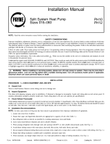
2, Assemble the Accurator body (see Fig, 18) using the correct
factory supplied piston (refer to Table 7),
TEFLON SEAL
\ _ _ TO INDOOR
__{___ _ COIL
PISTON \
CAP WITH ORIFICE BODY
NOTE: Arrow on AccuRater body points in free flow direction, away from the
indoor coil.
A09501
Fig. 18 - AccuRater (bypass type) Metering Device
Components
3, Attach the complete Accurator assembly to the flare connec-
tion end of the filter drier
4, Braze the completed filter drier/Accurator assembly to the
liquid service valve.
5, Connect the field supplied line set to the filter drier/Accura-
tor assembly and the suction valve. A sweat connection is
required at the suction valve and flare connection is required
for the nfixed phase line,
6. Insulate any exposed areas between the line set and the li-
quid valve.
Failure to follow this caution may result in equipment damage
or improper operation.
To prevent damage to unit or service valves observe the
following:
• A brazing shield MUST be used.
• Wrap service valves with wet cloth or use aheat sink
material.

38QRF Units
1. Assemble the connector tubes to the factory supplied filter
drier by brazing the factory supplied flare connectors to the
inlet and outlet for the filter drier (see Fig. 19)
BODY
--_Eo_BB,
METEREDFLOW
METERED OW
HEATING
A09507
Fig. 19 - 38QRF018-036 Connector Tube Assembly
2. Perform step 2 and 3 from the 38HDF section.
3. Remove the plastic cap from the liquid and suction service
valve on the 38QRF unit and assemble the heating piston
and piston cap supplied with the outdoor unit as shown in
Fig. 20.
--PISTON
HEATIN6
_ cFoLNANR_cPISTONCAP
TOR
METERED FLOW
HEATING
Fig. 20 - AccuRater (bypass type)
Metering Device Components
A07407
NOTE: The Teflon seal on the piston should point towards the
liquid service valve. The size of the factory supplied piston might
have to be adjusted for long line applications (over 80 ft / 24.4 m).
Refer to the Duct Free Long Line Application Guide for additional
information.
4. Attach the flare end of the filter drier assembly to the piston
cap (see Fig. 20).
5. Connect the field supplied line set to the filter drier as-
sembly and to the suction valve.
6. Insulate any exposed areas between filter drier and liquid
valve.
Complete Outdoor Power and Control Wiring
ELECTRICAL SHOCK HAZARD
Failure to follow this warning could result in personal iniury or
death.
The unit cabinet must have an uninterrupted or unbroken
ground to minimize personal iniury if an electrical fault should
occur. The ground may consist of electrical wire or metal
conduit when installed in accordance with existing electrical
codes.
UNIT DAMAGE HAZARD
Failure to follow this caution may result in equipment damage
or improper operation.
Unit failure as a result of operation on improper line voltage or
excessive phase imbalance constitutes abuse and may cause
damage to electrical components. Such operation could void
any applicable Carrier warranty.
ELECTRICAL SHOCK HAZARD
Failure to follow this warning could result in personal injury or
death.
Before performing service or maintenance, be sure indoor unit
main power switch is turned OFF and indoor blower has
stopped.
Lock out and tag switch with a suitable warning label.
Power Wiring
1. Mount outdoor power disconnect. The unit is factory wired
for the voltage shown on the unit nameplate. The fused dis-
connect switch nmst be provided within sight of the unit,
readily accessible, but out of reach of children. Provisions
for locking the disconnect switch on the OFF (open) posi-
tion is advisable. The disconnect switch must comply with
NEC and local codes. Protect the unit and wiring using only
the recommended fuse/circuit breaker size. See Table 10..
2. Run power wiring from main box to disconnect per NEC
and local codes.
3. Run power wiring from the disconnect switch to outdoor
unit. Use only nfinimum 60°C copper conductors between
the disconnect switch and the unit for field power connec-
tion.
4. Route the field power wires through the conduit connection
opening in the unit side panel and connect in junction box
as shown in Fig 21. The unit and power wiring must be
grounded.
I m =GROUND LEAD m GROUNDING LUG
SINGLE-PHASE F"'3
PER NEC ] __ BLK
[ SINGLE-PHASE U_IT
THREE-PHASE
CONN TO
DISCONNECT
PER NEC
=GROUND LEAD
LEGEND
NEC -- National Electrical Code
-- Splice (field)
-- -- , Field Wiring
-- Factory Widng
,._..-- BLK
=_-..- BLU
,_ YEL
,_ GROUNDING LUG
THREE-PHASE UNIT
Fig. 21 - Line Power Connections
A08251
NOTE: Operating unit on improper line voltage constitutes abuse
and could affect Carrier warranty. Do not install unit in a system
where voltage may fluctuate above or below permissible limits.

Control Wiring
The control circuit is 24 volts AC (naininmm 40VA) supplied from
the indoor unit,
1. Make sure you have enough control wires to cover the dis-
tance between the indoor and outdoor unit,
2, Route one end of the control wiring through the opening
provided in the unit side panel and connect to the control
terminal strip using either Fig. 21 for 38HDF units and Fig.
22 for 38QRF units,
Indoor
Terminal
Board
Indoor _ _4v
Board
COHPR
T°v2°;
Board I_ I
A09508
Fig. 22 - 38HDF Control Terminal Strip
Indoor_
Board
Outdoor ...... _o i41_it _
Terminal _o _il o
Board ............._o _LL r_
Terminal
Board
Fig. 23 - 38QRF Control Terminal Strip
A09509
NOTE: Use No. 18 AWG color-coded, insulated (35°C mininmn_) wire. If the distance between the indoor and outdoor unit is greater than
100 ft. (30.5 m), as measured along the control voltage wires, use No. 16 AWG color-coded wire to avoid excessive voltage drop.
10

38HDF /
38QRF
UNIT
SIZE
018
024
030
V-PH-Hz
Table 10 - 38HDF / 38QRF Electrical Data
VOLTAGERANGE* COMPRESSOR OUTDOOR FANMOTOR
Min Max
187 253
187 253
187 253
187 253
187 253
414 506
187 253
187 253
414 506
RLA LRA FLA
NEC Hp
0.125
0.125
0.25
0.25
0.25
0.25
0.25
0.25
0.25
kW Out
MIN CKT
AMPS
208/230-1-60 9.0 48.0 0.80 0.09 12.1
208/230-1-60 12.8 58.3 0.80 0.09 16.8
208/230-1-60 14.1 73.0 1.50 0.19 18.4
208/230-1-60 16.7 79.0 1.50 0.19 22.3
035 208/230-3 -60 10.4 79.0 1.50 0.19 14.5
460 -3 -60 5.8 79.0 0.80 0.19 8.7
208/230-1-60 17.9 112.0 1.45 0.19 23.8
036 208/230 -3 -60 13.2 88.0 1.45 0.19 18.0
460 -3 -60 6.0 44.0 0.80 0.19 8.3
Table 11 - 40QNC, QNQ Fan Coil Electrical Data
VOLTAGE RANGE* FAN POWER
UNIT SIZE V-PH-Hz Motor Power MIN CKT FUSE/CKT
Min Max FLA
(Watts) AMPS BKR AMPS
40QNC01824 208/230-1-60 187 253 0.38 64 0.48 15
40QNC030 208/230-1-60 187 253 0.38 74 0.48 15
40QNC036 208/230-1-60 187 253 0.44 74 0.55 15
40QNQ018 208/230-1-60 187 253 0.38 64 0.48 15
40QNQ024 208/230-1-60 187 253 0.38 64 0.48 15
40QNQ030 208/230-1-60 187 253 0.38 74 0.48 15
40QNQ036 208/230-1-60 187 253 0.44 74 0.55 15
FUSE/
HACR
BKR
AMPS
2O
25
3O
35
2O
15
4O
3O
15
LEGEND:
FLA - Full Load Amps
LRA - Locked Rotor Amps
NEC- National Electrical Code
RLA - Rated Load Amps (compressor)
* Permissible limits of the voltage range at which the unit will operate
satisfactorily
NOTES:
1. Control circuit is 24-V on all units and requires external power
source. Copper wire must be used from service disconnect to unit.
2. All motors/compressors contain internal overload protection.
3. In compliance with NEC (USA Standard) requirements for multimo-
tot and combination load equipment (refer to NEC Articles 430 and
440), the over current protective device for the unit shall be fuse.
4. Motor RLA values are established in accordance with UL (Under-
writers' Laboratories) Standard 465 (USA Standard).
5. 38QRF018-030 units are only available in single-phase voltage.
6. Unbalanced 3-Phase Supply Voltage
Never operate a motor where a phase imbalance in supply voltage is
greater than 2%. Use the following formula to determine the percent-
age of voltage imbalance:
= 100 X max voltaqe deviation from averaqe voltaqe
average
EXAMPLE: Supply voltage is 460-3-60
A 8 C AB = 452v
M_OTO_j_R BC = 464v
AC = 455v
Average Voltage = 452 + 464 + 455
3
= 1371
3
= 457
Determine maximum deviation from average voltage:
(AB) 457-452 = 5v
(BC) 464-457 = 7v
(AC) 457-455 = 2v
Maximum deviation is 7v.
Determine percentage of voltage imbalance
7
% of voltage imbalance = 100 x 5-7-
= 1.53%
This amount of phase imbalance is satisfactory as it is below the maximum
allowable of 2%.
IMPORTANT: Contact your local electric utility company immediately if the
supply voltage phase imbalance is more than 2%.
cQ0s
11

o
COMH
I o I
m_s
I I _ I
' I r-
, 14q, l.lol
I o Ic:
fEL YEL
LEGEND
(_ TERMINAL (MARKED)
0 TERMINAL (UNMARKE(}}
SPLICE
TERHIN_L BLOCK
FACTORY WIRING
FIELD CONTROL WIRING
OPTIONAL WIRING
'ODULAR ",A"
CO qTROL PCB
]R (}O! ,10
THERMISTOR EQUIVALENCE
TENPERATURE RESISTANCE
+F "C :_
3S 6,500
22 ]7_40©
32 0 32_500
ALL THERMISTORS ARE IDENTICAL
(ilt, ( ONTAETOR
C;PaC I TCR
CO_> COPIRES 0i_
FC FAN CAPACITOR
EOUIP.6ND. EOUIPME_T 6ROUN:¸}
HPS HIGH PRESSURE S_ITCH
IDFH INDOOR FAN MOTOR
LLPS LIOUli) LOW P_E_SUi_E S_JITCH
OF_ CUTbOOR FAN _40TCR
OFR OUTDOORFAN RELAY
OL OVERLO_'D
IPCB t4_IN COI'_TROLPRINTED
CIRCUIT BOARD
_T..... '.................
TP TEST P(I II,_T
TRA_ TRANSFORMER
0 '_N/YEL
FANI I I--
4/. _1\. 01 HI OH_,,£LL
N0 TE
. IF 4N_ OF THE )RIHN_L _]RE FURNIgHED
MUST BE REPLACED, IT MUST BE REPLACE{)
_,'ITH TYPE 90°C ,_IRE OR ITS EOdlVALENT.
2. ',_II_E IN ACCOPDANCE WITH N_TIOI'_L
ELECTRICAL CODE (N.E.C.} AI,_[} LOCAL CODES.
3. COMPRESSOR AND FAN MOTORS_RE PROTECTED B"
INTERNAL THERmaL OVERLO_DS.
4. T_ANSFORMER H45 I_TER_AL 2A THERH_L FUSE ON
THE P_IH:RY SIDE.
TB3
TO UNIT )[ XX}N;E(T
E{_'L[ P. ( ND
38HDF OUTDOOR CONDENSER
3LK RED
EOUIP _D_ _ _s i 208/2301,
7PH
:,LK }_, s.,._iE:0::_
i TO
OUTDOOR
8LK ¢]_ -2 . ,_IT
D 15CONNECT
_BLK
OFR
TRSN
BLU
RED
m
E_
EZ3
TO H ](JH ,_ALL
TO H]t;H,,:LL R
EB]
T_£
Fig. 24 - 40QNC01824 Matched with 38HDF Typical Wiring Schematic
......../
...... /
A08367
12

[ r
Iq'lddil'l I
b
12
YEL YEL
CONTACTOR
_,p CAPACITOR
CH C ,'_ KC_'SE HE,_TER
CO_4P COHPRESEOR
CHS C_A_KC_SE HEATER S_;ITCH
OFT DEFROST THERMOSTAT
FC FAN CAPACITOR
EOtJIP.CNI_. EOUIHtENT 6ROUND
HPS HICH _RE_SURE S_ITCH
IOFM INDO01_FAt_ _OTOR
LLPS LIOUID LO_ PRESSURE S_;ITCH
OA5 OUTDOORAIR SENSOR
OFH ObTDODR F,_N _OTOR
OFR OUTDOORFA_ RELAY
OL O?E_LO'_D
IPC8 It_I_x CONTROL
PRINTED CIRCUIT BO4R8
i!73 ..... ......
LOU'_ER STEPPER HOTOR
TP TEST POI T
TR_ Tbq SFOR E_
LEGEND
(Z} TERMINAL (HARKED}
0 TERMINAL (UNMARKED}
_PLICE
El TERNIN_L 8LOCK
FACTORY _IRING
FIELD CONTROL WIRIN6
NODULSR "A"
CONTROL ]PCB
_GRN/YEL
= i
_G_N'_L I
.......... 8 32d4..uN_¢,; HI OHm,,',£LL
THEAt[ST(}R EOk, Ii'_LENCE
TEHPERATURE RES[STS, NCE
F °(" c_
9S 35 6, O0
72 22 ] 1 400
1_2 0 2, SO0
aLL THERH[STO:_S /-RE IDENT[CSL
NOTES
i. IF _ Y OF THE O [OI[_L _dlqE FURSlSHEB
U_T BE REPLACE[}, IT M T 3E EPLA(E
_,ITH T/'>E 90 _d[ E IT E(LIV;LENT.
2. dIRE IN A(LORD_N(E WITH N_TI _L
ELE{TRI 5L 'O(E N.E.. AN} LO 5L O)E .
OblP E q(R AN} FAN IflOT(R -tRE PR'_TE'TE
BY ]qTERN,_L THERq_L D'/E_LOA}8.
4. TRA F(}_HE_ HAS I TE! AL A THE_L FJSE (}b
THE I'RII' AqY II}E.
COMPRESSOR(IANCKCASE HEATEr [NST&LLE)
ON S380NFO X_.
_ OUTCOOi!FAIEFdST _
T_;3
_ LU_
__ BARE ZOF>_ER
T NIT ]q O_l ECT
EOUIP. GND
380RF OUTDOOF< CONDEN%ER
_ Optional on 38QRF018/024 Models
" OH s K _ P08/20Y/[>H
CIIC NE;T
L "'"(::_' BLKRED
_,_ _ BLK
OFR
,/--
_Q
0_9
_'_'_F[ LI
FT
BLU
,,/>4K
TRAN
8LK
TO H[OH',dALL B
[_3 TO H[GHW;LL '_
TO H[(H,_,LL DT
..........TO H[{_HidALL {_
..............TO H[CHWALL Y
TO H[GHW_LL R
TO H[OH',dALL 0
T_m
Fig. 25 - 40QNQ018,024 Matched with 38QRF Typical Wiring Schematic
_.J
J
A08368
13

( {ONTA[TBt
(AP {AP,_BITOR
COM_ CO_'PE BOR
FG FA_ GAP<CITOR
EE_UIP.GND. EOUIP_ENT GR{_LINb
HPB HICH PRESSURE SWITCH
IDFM I_xDO0;l FAN MOTOR
LLPB L]@UlB LOW PRESSUREBW]TCH
BFM BUTBBBR FAN HBTBR
BFR BUTBBBR FAN RELAY
OL OVERLOAD
_PCB MAIN CONTROL
PRI_TE[} CIRCUIT BOARD
BTM LOUVERSTEPPER MOTOR
TP TEST POINT
T_AN TRANSFORMER
I
CONTiOL IP i_
I/I} BOAR{} INtDOR FAN
LEGEND
(_ TER_INAL {_ARKEO?
O TERMINAL (UNHARKE{}}
@ BPLICE
TERMINAL BLOCK
FACTORY WIRING
FIELD COHTROL WIRING
F]ELDPOWER WIRING
_CCEBSORYOR OPTION#L WIRING
F("
THEAI[ }TOA E©U I /ALE[ CE
TEHPEASTURE RES [ ST AqCE
*_F °( l]
] } }S L , [ OI 0
,72 22 400
3_ 0 3:;' SO0
ALL THERN] TOR ARE IDENTICAL
} I IF Nt OF THE O I,%IflAL w[ E FBRNI HED
HU'T BE _E LACE, IT PUT BE E>L_'CEO
WITH TYPE 90'C WIRE OR IT q E UI,ALE T.
21 WIRE I A( 'RD,_ (E :,IITH NATIONAL
ELEGT ]C#L (O}E k.E.(. } AI,_BL(_L OBEB.
3, COI'I*>_EBO_ #NO FAN 40TO_ #BE '_OTECTE
PY [ TERNSL THEB AL OVEBLO<B_,.
TR,_NF}_HER H& I TERN,SL2A THE_I'_L FJBE
o THE PRIMAI_Y BIDEI
BLK
I FiN
2 GR CO_PR
TO UNIT DISCONNECT
EO I_< OND
d.,%NL, <_L< HI@HW,£LL
HI}F O( TDOOR CONDENSER
EOL]P ON)_ _ e xi _08/220V
i
I>H
TO
T
3LK _ _ . U IT
Bi9( ONNECT
J
_ LK
OFR
m
[3S3
E3
TR_N
E_
E_
BLU _ TO HIGHWALL Y
W/RNK
TO HIGHWALL R
[i3
T_
Fig. 26 - 40QNC030, 036 Matched with 38HDF Typical Wiring Schematic
......./I
j/
A08369
14

YEL YEL
CONTACTOR
"_) C4>A{ ITCR
_t C[/a!\KCt, E HEATER
CO_P COMPRESSOR
CHS CR_NLCAgE HEATER SWITCH
DFT bEFROgT THERMOSTAT
FC FAN CAPACITOI_
EOU[P.(_Nb. EOUII'_'!ENT GROUNI)
HP_ HIGH PRE55U_E 5WITCH
II}F_ ]_I}OOR FAN MOTOR
LLPS L]OdI8 LOW PRESSURE 5WITCH
OA5 ObTOOORair SENSOR
OFM OUTDOORFAN HOTOR
OFR OUTDOORFAN REL_
OL OVERLOAD
IPCB _AIN CONTROL
PRINTED CIAC{_[T BOARD
LO ,,ER 5TEI' E HOTOR
TP TEST POINT
TR_N TRa\SFO_MER
E
I/0 [()SAD [N[}OOA FaN
f!ODUL '-',A "D"
CONTROL IPCB
]OC
_'LK 8LU .
TERMINAL M_AKE }
@ TERMINAL (UNM_AKEg}
0 SPLICE
[_ TEAMINbL 8LOCK
FACTORY w1?INS '_
o
FIEL COT?L WIRIN '\_ORN
FIEL POWERWIRINS F_
A E 'RY {R
............ ..... 4()(NC030 038 HIOH>:ALL
THEG ,I :TO:_ EOL I VALENCE
TE PERATL RE AES I STANCE
°F '_C s
9_ 35 6,500
72 2P ] I, 400
32 0 32 500
ALL THERMISTORk ARE IDENTICAL
N<3TEc
2. 4IRE IN aCCOR MCE ,_ITH hATIOKAL
ELE(TRICAL CO)E (N. E.C. ) AND LO(AL C0¢E5.
3. COHPRESSORAND FAN MOTOR5 ARE PROTECTED
8Y INTERNAL THERnAL OVEALOADS.
4. THETRANSFORMERPR[MaRY<[nHASE._ .INTERNAL 2A THERMAL FUSE ON
5. COHPRESSORCRANCKCASEHEATER INSTALLED
ON 538QNF030.
_LK _q
_'HT ....................... OUTD_EROST
4 REb OD FeN _]
3 ORN RV5
Z'4 ss" I
TB3
DL_
TO :NIT D[SCONIECT"
EQUIP. OqO
.......%,Y uuTDOOA tu u_
_pptional on 38QRFO036 Models
[ Standard on 38QRF030
I _ILK+eLK_'_:_ N(TE 5
__-L " ,.....
[ _ ?,_}Hr, BLF E)
h
EOUIP N)_ _ _ Ii 20 /230V
] [>H
_ _.?. , EE NOTE #)
' TO
)JTD} R
JNIT
BLK _ _ m 1 } I'NE:T
_BLK
OFA
/
OAS
)FT
BLU
M/PNK
TAAN
SLK
TO H[GHW,L,LL B
{Z] .... TO HIGH*ALL A
TO H[GHWaLL OT
T( H[(HW_LL (
T( HIGHbaLL Y
.............TO H[GHWALL /
TO H[GH_ALL 0
T8
Fig. 27 - 40QNQ030, 036 Matched with 38QRF Typical Wiring Schematic
/
A08370
15

Run Power Wiring for Indoor Unit
Be sure field wiring complies with local building codes and NEC,
and unit voltage is within limits shown in Table 11.
Contact local power company for correction of improper line
voltage.
ELECTRICALSHOCK HAZARD
Failure to follow this warning could result in personal injury
or death.
Before installing, modifying, or servicing system, main
electrical disconnect switch must be in the OFF position.
There nmy be more than 1 disconnect switch. Lock out and
tag switch with a suitable warning label.
[]NIT DAMAGE HAZARD
Failure to follow this caution may result in equipment damage
or improper operation.
Unit failure as a result of operation on improper line voltage or
excessive phase imbalance constitutes abuse and may cause
damage to electrical components. Such operation could void
any applicable Carrier warranty.
NOTE: Use copper wire only between disconnect switch(es) and
unit.
NOTE: Install branch circuit disconnect of adequate size to handle
unit starting current per NEC. Locate disconnect within sight of,
and readily accessible from, unit, per section 440-14 of NEC.
Some codes allow indoor unit to share disconnect with outdoor
unit if disconnect can be locked; check local code before installing
in this manner.
The 40QNC/QNQ units require their own power supply.
1. Locate the indoor power supply.
2. Locate and install disconnect switch per NEC and local
codes.
3. Run power supply wiring to disconnect switch.
4. Run power wiring from disconnect switch to wall mount
area.
5. If any accessories are being installed, refer to the individual
accessory instructions for guidance on wire routing at this
time.
Install All Power_ Interconnecting Wiring_ Piping and
Drain Hose to Indoor Unit.
1. Run control wiring from the outdoor unit through the access
hole in the wall and make sure you have enough wire to
reach the control box of the unit once hung on the mounting
plate.
2. It is a recommended that flare connections is located on the
outside of the wall where the indoor unit is to be mounted.
If an extension pipe is required to facilitate this location,
measure, fabricate and install the extension pipes to the in-
door unit before hanging the unit on the mounting bracket.
3. If piping connections are on the outside wall, pass the pipes
(refrigerant and drain) through the wall sleeve and then
hook the indoor unit body on top of the wall hanging brack-
et. Support the unit away from the bottom using a tool or a
piece of wood.
NOTE: Tie together the refrigerant piping, the drain hose, and the
electrical connection wires and ensure that the drain hose is at the
bottom as shown in Fig. 28.
(i) Indoor unit piping
@ Connection w_dng
@ Drain hose
Fig. 28 - Location of Piping, Hose, and Wiring
A08364
4. If required make the flare connections.
5. Route the power and control wiring through the back side
of the unit and to the control box area. If the wired remote
or zone manger accessory are to be used, perform any modi-
fications required at this time. Refer to the Accessory install-
ation instructions).
6. Remove the control box cover and finish all indoor unit
wiring connections as shown on the wiring diagram or in
the accessory installation instructions. Replace the control
box cover.
7. Fix the bottom part of the unit to the wall mounting bracket
and push it carefully until the two bracket hooks fit into the
marked places at the base of the unit until it snaps into
place. See Fig. 29.
16

Wall
Hanging
Bracket Hook
Hole
UNIT SIZE
40QNC01824
40QNC030
40QN0036
40QNQ018
40QNQ024
40QNQ030
40QNQ036
Retainer
Clip
A08365
Fig. 29 - Wall Mounting Details
8. If the refrigerant piping connections are located outside the
wall, tighten the flare connections as shown in Fig. 30. Insu-
late all exposed refrigerant lines and secure to the wall and
fill any void spaces in the hole.
®
@ Adjustable wrench or torque wrench
@ Outdoor end
@ Indoor end
Fig. 30 - Tightening Connections
A07201
USER INTERFACE
The indoor unit includes a wireless remote control to operate the
unit (an Owner's Manual is supplied with the unit). If you have
two units installed in the same space and they need to work
independently, the remote controls and the units need to be
configured as follow:
Unit Configuration
Turn the unit off by pressing the IQL). Press and hold the M and
A
=_/_/IIbuttons of the remote control for more than 5 seconds. The
display will be cleared and the time segments will display the first
configuration item (rAdr=remote address) and the temperature
segments will display the default value of this configuration item
(ab=control of both indoor units). Press A and V to change the
default value to the new value of (a) or (b). Press the //I button to
transmit the new configuration to the unit. Press the I_ button to
leave the configuration menu.
Remote Control Configuration
Turn the unit off by pressing the IQL)button. Press and hold the
A
v
and buttons for more than 5 seconds. The display will be
cleared and the time segments will display the first configuration
item (CH=remote address) and the temperature segments will
display the default value of this configuration item (Ab=control of
both indoor units).
Press A and V to change the default value to the new value of (a)
or (b). Press the :'/_ button to transmit the new configuration to the
unit. Press the I_ button to leave the configuration menu.
NOTE: When 30 seconds have elapsed and no buttons have been
pressed, the remote control will automatically exit the
configuration menu and resume its normal operation.
A wall mounted control or zone manager can be used to control a
unit or multiple units.
Wired Control
If a wall mounted wired control is required the following steps
should be performed at the same time the indoor control and power
wiring are being connected:
1. Unplug the connector on J5.
2. Remove the wire harness from the wired control box
3. Plug one end of the wire harness into the J5 connector on
the board
4. Route the other end of the wire harness to the back of the
unit along the low voltage wiring
5. Connect the other end of the wire harness to the field sup-
plied wiring between the indoor unit and the wired control
as shown in wired control installation instructions and Fig.
31.
17

I .... Fbd ...... I
Lo.°
----T-
i_) 5 pins II II
0 hdoor unit
Room Controller
0 Main electronic card
@ 4 pins terminal Mock placed on e_emal control box
0 Wires supplied by the installer
_) Terminal block in the Room _ntro_er
Fig. 31 - Control Wiring Between Indoor and Outdoor Units
A09512
Up to six units can be daisy-chained and controlled from one wired control.
UNIT1 UNIT 2
1 1
Js
(Z)
WIRED CONTROLLER
UNIT
(1) (!)
3 --- UP TO 6 UNITS
_J5
(9
A - MAIN BOARD
C) " WIRING KIT 33MC9005
0 " BLAC_
(T) - RED
C) " WHITE
* 100ohm Resistor
Fig. 32 - Multiple Unit Control Wiring
A09513
18

Zone Manager
If a Zone Manager is required, the following steps should be
performed at the same time the indoor control and power wiring
are being connected:
1. Plug the communication board to the J8 as shown in Fig. 33
2. Connect one end of the wire harness supplied with the Zone
Manager to the communication board.
3. Route the other end of the wire harness along the voltage
control to the back of the unit.
4. Connect the other end of the wire harness to the field sup-
plied wiring that will be connected to the zone manager as
shown in Fig. 33. (Shielded cables are required. Refer to
Zone Manager Installation Instructions for further informa-
tion.)
f
,,__.,
®
GREY
(_ [ BLUE @._CB
12v
a ®
O Main board
(_) Communication board (supplied with the kit)
(_) 5*cable wiring (supplied wilh the kit)
@ Auxiliary terminal block (supplied with the kit)
(_) Wiring by the installer
(_ Zone Manager terminal block (mounted on the Zone Manager)
O Indoor unit
I"-
I
®
m
®
/.,
T--- I
-4 II
1.' [
l, '
,,
[1 [ I I !,,,,,]I ®
go o>
z_
Fig. 33 - Wiring for Zone Manager
A09514
19

START-UP
Preliminary Checks
1. Check condensate drainage system; on the opposite side of
the drain connection, insert a water bottle up into the fan
coil unit and fill the drain pan. Water must flow steadily; if
not, check the pipe slope or inspect for any pipe restrictions.
2. Make sure all wiring connections are correct and they are
tight.
3. Field electrical power source must agree with unit name
plate rating.
4. Check that all barriers, covers, and panels are in place. En-
sure that the filters and return-air grilles on the indoor unit
have been installed and that the discharge louvers are posi-
tioned correctly.
5. All service valves must be closed.
6. On units with crankcase heaters, ensure belly-band heaters
are tight around the compressor.
Evacuate and Dehydrate the System
UNIT DAMAGE HAZARD
Failure to follow this caution may result in equipment damage
or improper operation.
Never use the system compressor as a vacuum pump.
Using Vacuum Pump
1. Completely tighten flare nuts A, B, C, D, connect manifold
gage charge hose to a charge port of the low side service
valve. (See Fig. 34.)
2. Connect charge hose to vacuum pump.
3. Fully open the low side of manifold gage. (See Fig. 35)
4. Start vacuum pump
5. Evacuate using either deep vacuum or triple evacuation
method.
6. After evacuation is complete, fully close the low side of
manifold gage and stop operation of vacuum pump.
7. The factory charge contained in the outdoor unit is good for
up to 25 ft. (8 m) of line length. For refrigerant lines longer
than 25 ft (8 m), add 0.3 oz. per foot of extra piping up to
the maximum allowable length.
8. Disconnect charge hose from charge connection of the low
side service valve.
9. Fully open service valves B and A.
10. Securely tighten caps of service valves.
Outdoor Unit Refrigerant Indoor Unit
_B Low Side
High Side D_
Service Valve
A07360
Fig. 34 - Service Valve
Manifold Gage
500 microns __{(('_
Low side valve _,v --_
Charge hose-_
\
High side valve
/ Charge hose
Vacuum pump
Low side valve
A07361
Fig. 35 - Manifold
Deep Vacuum Method
The deep vacuum method requires a vacuum pump capable of
pulling a vacuum of 500 microns and a vacuum gage capable of
accurately measuring this vacuum depth. The deep vacuum method
is the most
liquid water.
Z
O
ft.
O
m
)ositive way of assuring a system is free of air and
See Fig. 36)
LEAK IN
SYSTEM
,VACUUM TIGHT
TOO WET
TIGHT
DRY SYSTEM
1 2 3 4 5 6 7
MINUTES
Fig. 36 - Deep Vacuum Graph
A95424
20
/