Broan GP5RD Installation guide

Category
Heat pumps
Type
Installation guide

This manual is also suitable for

13 SEER
USER’s MANUAL & INSTALLATION INSTRUCTIONS
R-410A Single Package Air Conditioner
P5RD SERIES
Please read this information thoroughly and become familiar with the capabilities and use of
your appliance before attempting to operate or maintain this unit. Keep this literature where
you have easy access to it in the future. If a problem occurs, check the instructions and follow
recommendations given. If these suggestions don’t eliminate your problem, call your servicing
contractor.
These instructions are primarily intended to assist qualifi ed individuals experienced in the
proper installation of this appliance. Some local codes require licensed installation/service
personnel for this type of equipment. Please read all instructions carefully before starting the
installation.
DO NOT DESTROY. PLEASE READ CAREFULLY AND
KEEP IN A SAFE PLACE FOR FUTURE REFERENCE.
IMPORTANT
2
Important Safety Information ....................................4
Air Conditioner Installation ....................................... 5
General Information .................................................. 5
Before You Install this Unit ........................................5
Locating the Air Conditioner ....................................5
Unpacking the Unit ..................................................5
Minimum Clearance Requirements ......................... 5
Service Access Clearances .................................. 5
Clearances to Combustible Materials ...................5
Condensate Drainage ..............................................6
Ducting System ..........................................................6
Installing Return & Supply Fittings............................6
Supply Duct ...........................................................6
Return Duct ...........................................................7
Locating & Installing the Return Air Assembly ..........7
Connecting the Return & Supply Air Flexible
Ducts ........................................................................ 7
Locating & Installing the Supply Dampers ................7
Electrical Connections ............................................... 8
Pre - Electrical Checklist ........................................... 8
Line Voltage .............................................................. 8
Overcurrent Protection ............................................. 9
Grounding ................................................................. 9
Thermostat / Low Voltage Connections .................... 9
Optional Outdoor Thermostat ................................. 9
Cooling Thermostat ................................................ 9
Heat/Cool Thermostat ............................................ 9
Blower Speed ......................................................... 10
Standard Motor (2, 2.5 and 3 Ton) ....................... 10
High Effi ciency Motor (3.5, 4, and 5 Ton) ............. 10
Startup & Adjustments ............................................ 11
Pre - Start Checklist................................................ 11
Start - Up Procedure ..............................................11
System Cooling .................................................... 11
Short Cycle Protection ......................................... 11
Emergency Heat .................................................. 11
Adjustment of Refrigerant Charge .......................... 11
Charging an R410A Unit in AC Mode with Outdoor
Temperatures above 55° F .................................... 11
Air Conditioner Maintenance ................................... 12
Component Functions ............................................. 12
High Pressure Switch ............................................. 12
Low Pressure Switch .............................................. 12
Replacement Parts ................................................... 12
Figures & Tables ....................................................... 13
Figure 10 - Unit Dimensions ................................ 13
Table 5 - P5RD Physical Data .............................. 13
Electrical Information .............................................. 14
Figure 11 - Wiring Diagram - w/ ECM Motor ........ 14
Figure 12 - Wiring Diagram - w/ PSC Motor ......... 15
Refrigerant Charging Charts .................................. 16
Table 6 - 2 Ton Units ............................................. 16
Table 7 - 2.5 Ton Units .......................................... 16
Table 8 - 3 Ton Units ............................................. 17
Table 9 - 3.5 Ton Units .......................................... 17
Table 10 - 4 Ton Units ........................................... 18
Table 11 - 5 Ton Units ........................................... 18
Installation / Performance Checklist ....................... 20
USER INFORMATION
Important Safety Information ....................................3
Operating Instructions ...............................................3
Cooling Operation .....................................................3
Heating Operation .....................................................3
Turning the Air Conditioner Off ..................................3
Operating the Indoor Blower Continuously ...................3
Air Conditioner Maintenance .....................................3
Troubleshooting ..........................................................3
WARRANTY INFORMATION
A warranty certifi cate with full details is included with the
Air Conditioner. Carefully review these responsibilities with
your dealer or service company. The manufacturer will not
be responsible for any costs found necessary to correct
problems due to improper setup, improper installation,
adjustments, improper operating procedure on the part
of the user, etc. Some specifi c examples of service calls
which are not included in the limited warranty are:
Correcting wiring problems in the electrical circuit
supplying the Air Conditioner.
Resetting circuit breakers or other switches.
Adjusting or calibrating of thermostat.
INSTALLER INFORMATION
3
Figure 1. Digital Thermostat
Fan
Mode
Temperature
Selector
System
Mode
OPERATING INSTRUCTIONS
NOTE: Thermostat styles vary. Some models may not
include the AUTO mode and others will have the AUTO
in place of the HEAT and COOL. Others may include all
three. Please refer to the thermostat manufacturer’s User
manual for detailed programming instructions.
NOTE: If the temperature level is re-adjusted, or the system
mode is reset, the fan and compressor in the unit may
not start immediately. A protective timer circuit holds the
compressor and the outdoor fan off for approximately three
minutes following a previous operation or the interruption
of the main electrical power.
Cooling Operation
1. Set the thermostat’s system mode to COOL or AUTO
and change the fan mode to AUTO. See Figure 1.
2. Set the temperature selector to the desired temperature
level. The outdoor fan, compressor, and blower motor will
all cycle on and off to maintain the indoor temperature
at the desired cooling level.
Heating Operation
1. Set the thermostat’s system mode to HEAT or AUTO
and change the fan mode to AUTO. See Figure 1.
2. Set the temperature selector to the desired
temperature level. The compressor, outdoor fan,
and blower motor will cycle on and off to maintain
the indoor temperature at the desired heating level.
IMPORTANT SAFETY INFORMATION
Safety markings are used to designate a degree or level
of seriousness and should not be ignored. WARNING
indicates a potentially hazardous situation that if not
avoided, could result in personal injury or death. CAUTION
indicates a potentially hazardous situation that if not
avoided, may result in minor or moderate injury or property
damage.
Turning the Air Conditioner OFF
Change the thermostat’s system mode to OFF and the fan
mode to AUTO (See Figure 1). NOTE: The system will not
operate, regardless of the temperature selector setting.
Operating the Indoor Blower Continuously
The continuous indoor blower operation is typically used to
circulate the indoor air to equalize a temperature unbalance
due to a sun load, cooking, or fi replace operation.
Set the thermostat fan mode to ON (Figure 1). The indoor
blower starts immediately, and will run continually until the
fan mode is reset to AUTO.
The continuous indoor blower operation can be obtained
with the thermostat system mode set in any position,
including OFF.
USER INFORMATION
AIR CONDITIONER MAINTENANCE
Proper maintenance is most important to achieve the best
performance from the appliance and should be performed
frequently at the beginning of each air conditioning season.
WARNING:
Your Air Conditioner contains liquid and
gaseous refrigerant under pressure. Installation
and servicing should only be attempted by
qualifi ed, trained personnel thoroughly familiar
with the equipment and safe responsible
refrigerant handling procedures. Failure to
comply with this warning could result in
equipment damage, personal injury, or death.
Keep the unit clean. Hose off periodically and keep unit
ns clear of leaves and grass clippings.
Keep the unit clear of obstructions. DO NOT obstruct
airfl ow with tall plants or shrubs. DO NOT store gasoline
or other fl ammable materials on or near the unit.
Never operate the appliance without a fi lter installed in
the return air duct. Inspect fi lters frequently and replace
when necessary with fi lter of same dimensional size.
TROUBLESHOOTING
If the unit fails to operate, check the following:
Check the thermostat setting. Make sure the system
mode and temperature settings are correct.
Check the electrical panel for tripped circuit breakers.
Check the fi lters for dust accumulation.
Check the unit and make sure it is clean and not covered
with grass or leaves.
If the items above don’t resolve your problems, then
call your nearest service technician.
4
INSTALLER INFORMATION
IMPORTANT SAFETY INFORMATION
Please read all instructions before servicing this equipment.
Pay attention to all safety warnings and any other special
notes highlighted in the manual. Safety markings are
used frequently throughout this manual to designate a
degree or level of seriousness and should not be ignored.
WARNING indicates a potentially hazardous situation that
if not avoided, could result in personal injury or death.
CAUTION indicates a potentially hazardous situation that
if not avoided, may result in minor or moderate injury or
property damage.
WARNING:
Shut off all electrical power to the unit before
performing any maintenance or service on the
system. Failure to comply may result in personal
injury or death.
WARNING:
Unless noted otherwise in these instructions,
only factory authorized parts or accessory
kits may be used with this product. Improper
installation, service, adjustment, or maintenance
may cause explosion, re, electrical shock or
other hazardous conditions which may result
in personal injury or property damage
WARNING:
P5RD units are fully charged with R-410A
refrigerant and ready for installation. When
a system is installed according to these
instructions, no refrigerant charging is
required. If repairs make it necessary for
evacuation and charging, it should only be
attempted by qualifi ed, trained personnel
thoroughly familiar with this equipment.
Some local codes require licensed installation
service personnel to service this type of
equipment. Under no circumstances should
the equipment owner attempt to install and/
or service this equipment. Failure to comply
with this warning could result in equipment
damage, personal injury, or death.
CAUTION:
This unit uses refrigerant R-410A. DO NOT use
any other refrigerant in this unit. Use of another
refrigerant will damage the unit.
WARNING:
The information listed below must be followed
during the installation, service, and operation
of this unit. Unqualifi ed individuals should
not attempt to interpret these instructions or
install this equipment. Failure to follow safety
recommendations could result in possible
damage to the equipment, serious per
sonal
injury or death
.
The installer must comply with all local codes and
regulations which govern the installation of this type
of equipment. Local codes and regulations take
precedence over any recommendations contained in
these instructions. Consult local building codes and
the National Electrical Code (ANSI CI) for special
installation requirements.
All electrical wiring must be completed in accordance
with local, state and national codes and regulations
and with the National Electric Code (ANSI/NFPA 70)
or in Canada the Canadian Electric Code Part 1 CSA
C.22.1.
This equipment contains liquid and gaseous refrigerant
under high pressure. DO NOT USE ANY PORTION OF
THE CHARGE FOR PURGING OR LEAK TESTING.
Installation or servicing should only be performed by
qualifi ed trained personnel thoroughly familiar with this
type equipment.
This unit is designed for outdoor installations only and
should be located in a position as shown on page 5.
Follow all precautions in the literature, on tags, and
on labels provided with the equipment. Read and
thoroughly understand the instructions provided with
the equipment prior to performing the installation and
operational checkout of the equipment.
5
12"
12"
24"
TOP OF UNIT
TO BE
UNOBSTRUCTED
0"
Figure 2. Clearance Requirements
AIR CONDITIONER INSTALLATION
General Information
The P5RD packaged air conditioner is designed only
for outdoor ground level installations and can be readily
connected to the high static duct system of a home.
This unit has been tested for capacity and effi ciency in
accordance with A.R.I. Standards and will provide many
years of safe and dependable comfort, providing it is
properly installed and maintained. Abuse, improper use,
and/or improper maintenance can shorten the life of the
appliance and create unsafe hazards.
To achieve optimum performance and minimize equipment
failure, it is recommended that periodic maintenance be
performed on this unit. The ability to properly perform
maintenance on this equipment requires certain
mechanical skills and tools.
Before You Install this Unit
The cooling load of the area to be conditioned must be
calculated and a system of the proper capacity selected.
It is recommended that the area to be conditioned be
completely insulated and vapor sealed.
Check the electrical supply and verify the power supply
is adequate for unit operation. The system must be wired
and provided with circuit protection in accordance with
local building codes. If there is any question concerning
the power supply, contact the local power company.
Survey the job site to determine the best location for
mounting the unit. If possible, select a site that is as
close as possible to the proposed return grille location.
The unit is securely packed at the time of shipment and
upon arrival should be carefully inspected for damage
prior to installing the equipment at the job site. Verify
coil fi ns are straight. If necessary, comb fi ns to remove
attened or bent fi ns. Claims for damage (apparent or
concealed) should be fi led immediately with the carrier.
Please consult your dealer for maintenance information
and availability of maintenance contracts. READ ALL
INSTRUCTIONS BEFORE INSTALLING THE UNIT.
Locating the Air Conditioner
Select a solid, level position, preferably on a concrete
slab, slightly above the grade level, and parallel to the
home. DO NOT PLACE UNIT UNDER THE HOME.
The hot condenser air must be discharged up and away
from the home, and if possible, in a direction with the
prevailing wind.
If practical, place the air conditioner and its ducts in
an area where they will be shaded from the afternoon
sun, when the heat load is greatest.
The length of the supply and return ducts should be
kept to a minimum with no sharp radius bends.
Overhead obstructions, poorly ventilated areas, and
areas subject to accumulation of debris should be
avoided. Do not place the unit in a confi ned space or
recessed area that will allow discharge air from the unit
to re-circulate into the condenser air inlet, through the
coil.
Consideration should be given to availability of electric
power, service access, noise, and shade.
Unpacking the Unit
It is recommended that the unit be unpacked at the
installation site to minimize damage due to handling.
CAUTION:
Do not tip the unit on its side. Oil may enter
the compressor cylinders and cause starting
trouble. If unit has been set on its side, restore
to upright position and do not run for several
hours. Then run unit for a few seconds. Do this
three or four times with fi ve minutes between
runs.
1. Remove the bands from around the unit.
2. Unfold the top and bottom cap fl anges.
3. Carefully remove the top cap and tube.
Minimum Clearance Requirements
Suffi cient clearance for unobstructed airfl ow through the
outdoor coil must be maintained in order to provide room
for proper servicing and achieve rated performance. See
Figure 2 for minimum clearances to obstructions.
Service Access Clearances
Blower access panel side .......................................... 24”
Electrical compartment access panel side ............... 12
Clearance between overhang and top of unit ........ 72
Clearance around condenser coil area to wall or
shrubs (excludes duct panel side) ............................. 12”
Clearances to Combustible Materials
Supply and Return Air Ducts .......................................0”
Duct Connection side ..................................................0”
6
Elbow
Figure 3. Drain Trap
P-Trap
Condensate Drainage
A 3/4” condensate fi tting extends out of the side of the
unit (Figure 3). The drain trap, shipped in the electrical
compartment, must be installed to prevent water from
collecting inside the unit.
1. Thread the elbow provided with the unit into the drain
connection until hand tight.
2. Connect the condensate tubing onto the fi tting, forming
a trap near the drain connection.
3. Route the condensate tube from the trap to a suitable
drain. NOTE: For proper drainage, make sure the trap is
level to the ground and tubing outlet is below trap level.
DUCTING SYSTEM
Air ducts should be installed in accordance with the
standards of the National Fire Protection Association
“Standard for Installation of Air Conditioning and Ventilation
Systems” (NFPA 90A), “Standard for Installation of
Residence Type Warm Air Heating and Air Conditioning
Systems” (NFPA 90B), these instructions, and all applicable
codes.
The supply duct system, including the number and type of
registers, will have much more effect on the performance
of the system than any other factor. The duct must be
suffi ciently large to conduct an adequate amount of air
to each register. See Table 1 and Figure 4.
The air conditioning output of the system will not cool
the home if air is lost to the outside through leaks in
the duct system. Ducts that are collapsed or restricted
by foreign objects will also prevent adequate air fl ow.
Note: For highly resistive duct systems it may be necessary
to add an additional return air duct and or supply to
achieve maximum performance and prevent coil icing
and refrigerant fl ood back.
ITEM
NUMBER
DESCRIPTION
1
12” x 20” Return Air
2
16” x 20” Air Filter
3
12” x 20” Grille
4
Supply Damper
5
14” Diameter Flex Return Duct
6
12” Diameter Flex Supply Duct
7
12” x 12” x 12” “Y” Fitting
Table 1. Typical Applications
Figure 4. Single and Multiple Duct Applications
MULTIPLE DUCT APPLICATIONSINGLE DUCT APPLICATION
Installing Return and Supply Air Fittings
The supply and return fi ttings are included with the unit and
located in the supply duct. They attach to the unit openings
(Figure 5, page 7) with a fl ange and bead arrangement
and may be secured with sheet metal screws. For easier
access, install fi ttings before positioning unit in fi nal
location. Air opening sizes are shown in Table 5 (page 13).
Supply Duct
1. Position the supply duct collar so the edge of the unit
opening fi ts between the fl ange and the bead.
2. Overlap the collar ends keeping the small screw holes
underneath.
3. Align the holes in the crimped area and install one
screw. Note: It may be necessary to loosen the four
screws that hold the transition duct in order to install the
supply fi tting. Re-tighten when installation is complete.
7
Locating & Installing the Return Air Assembly
To simplify installation, locate and install the return air
assembly fi rst. If desired, the return opening can be located
inside a closet with louvered doors that has an open area
equal to or greater than the 12” x 20” grille furnished.
The return air grille can be placed in the wall of a closet
and the air ducted into the fi lter box through a boxed-in
area at the closet fl oor level (Figure 6). Verify the fi lter
is readily accessible.
NOTE: The return air box with grille and fi lter should not
be located in heavy traffi c areas like hallways or center
of rooms. A good spot is in a corner or under a table, if a
minimum two inch clearance is available.
1. Start the installation from under the home by cutting a
small hole in the subfl oor. Determine how the fl oor joist
location will affect cutting the opening needed for the
return air box. NOTE: Floor joists are generally located
on 16” centers, leaving 14-3/8” between joists.
2. After measuring the return air box (approximately 12-
1/4” x 20-1/4”), cut the hole through the fl oor so that
the box will fi t between the fl oor joists. Care should be
taken when cutting through carpeting to avoid snags.
NOTE: In most installations it will be necessary to cut a
similar hole in the fi berboard directly under the hole in
the fl oor. However, if the fl oor is more than ten inches
deep, it will only be necessary to cut a hole for the collar
on the return air box or for the insulated duct.
14” Duct Dimples
Figure 5. Return and Supply Air Fittings
Supply Air
Return Air
Transition Duct Screws
4. Tap collar (if necessary) to ensure engagement with
unit opening and install second screw.
5. Tighten fi rst screw and rotate collar clockwise so joint
is near three o’clock position.
Return Duct
1. Align the slots with the holes in the collar and install
two screws.
2. Position the collar over the opening and align the four
notches in the collar with the four dimples in the panel.
3. Using self-drilling screws (10-16x.5) attach the collar
to the rear panel.
Figure 6. Return Air Box
Connecting the Return and Supply Air Flexible Ducts
The return duct for all units is 14” diameter.
The supply duct for all units is 12” diameter.
Flexible ducts can be connected to the corresponding
ttings with the clamps provided with the ducts. See
Table 5, page 13). Note: To prevent a loss in cooling
capacity, make sure all connections are tight.
The fl exible ducts may be cut to the required length,
see instructions packed with duct. Keep all ducts as
short and straight as possible. Avoid sharp bends.
Ducts may be spliced with sheet metal sleeves and
clamps.
After the inner duct is connected to the proper fi tting,
the insulation and plastic sleeve should be pulled over
the connection and clamped.
Homes with multiple supply ducts (or special
applications), a Y fi tting is available to divide the
supply air so it can be ducted to different areas of the
home for more effi cient cooling. Note: For maximum
performance, insulate the Y fi tting.
Locating & Installing the Supply Damper(s)
CAUTION:
If installing this air conditioning system in
conjunction with a furnace, a damper must
be installed in the furnace base assembly
to prevent cold air from being discharged
around the heat exchanger. Damage to the
heat exchanger and asphyxiation may occur if
a damper is not installed.
Check with the furnace manufacturer for damper
requirements. Failure to install the required
furnace damper may invalidate code agency
listing and limited warranty on the furnace.
3. Set the box into the opening and fasten with screws or
nails.
4. Install the fi lter and return air grille in the air box.
8
When locating the supply damper(s), carefully check
oor joists and frame members that could interfere with
the installation of the damper or fl exible duct. Ideally, the
damper (Figure 7) should be located in the bottom of the
main duct, forward of center of the home, at least three
feet from the nearest register. The round supply opening
in the slanted side of the damper should face the side of
the home where the air conditioner is located.
1. Locate the center of the heat duct by cutting a small
hole in the fi berboard below the duct at the desired
location.
2. Cut a hole approximately 3/4” larger than the damper
opening in the fi berboard.
3. Cut a 9-1/8” x 13-1/8” hole in the duct and bend over
all tabs fl at on the inside of the heat duct.
4. Insert the damper into the duct and bend over all tabs
at on the inside of the heat duct.
5. Seal the opening between the fi berboard and damper
or fl exible duct.
Figure 7. Supply Damper
ELECTRICAL CONNECTIONS
WARNING:
To avoid risk of electrical shock, personal
injury, or death, disconnect all electrical power
to the unit before performing any maintenance
or service. The unit may have more than one
electrical supply.
Label all wires prior to disconnection when
servicing the unit. Wiring errors can cause
improper and dangerous operation
All electrical connections must be in compliance with
all applicable local codes and ordinances, and with
the current revision of the National Electric Code
(ANSI/NFPA 70).
For Canadian installations the electrical connections
and grounding shall comply with the current Canadian
Electrical Code (CSA C22.1 and/or local codes).
Pre-Electrical Checklist
Verify that the voltage, frequency, and phase of the
supply source match the specifi cations on the unit
rating plate.
Verify that the service provided by the utility is suffi cient
to handle the additional load imposed by this equipment.
Refer to the unit wiring label for proper high and low
voltage wiring.
Verify factory wiring is in accordance with the unit wiring
diagram (Figures 11 or 12, pages 14 - 15). Inspect for
loose connections.
Line Voltage
A wiring diagram is located on the inside cover of the
electrical box of the unit. The installer should become
familiar with the wiring diagram before making any
electrical connections to the unit.
An electrical disconnect must be located within
sight of and readily accessible to the unit. This
switch shall be capable of electrically de-energizing
the unit.
Line voltage to the unit should be supplied from a
dedicated branch circuit containing the correct fuse
or circuit breaker for the unit. Incoming fi eld wiring
and minimum size of electrical conductors and circuit
protection must be in compliance with information listed
on the unit data label. Any other wiring methods must
be acceptable to authority having jurisdiction.
Provide power supply for the unit in accordance with the
unit wiring diagram, and the unit rating plate. Connect
the line-voltage leads to the terminals on the contactor
inside the control compartment. Extend leads through
power wiring hole (Figure 8). Connect L1 and L2 directly
to the contactor.
The unit requires both power and control circuit electrical
connections. Refer to the wiring diagram / schematic
Figure 8. Power Entry
Low Voltage
Line Voltage
9
COPPER WIRE SIZE — AWG
(1% Voltage Drop)
Supply Wire Length-Feet
Supply Circuit
Ampacity
200 150 100 50
6 8 10 14 15
46812 20
46810 25
44610 30
3468 35
3468 40
2346 45
2346 50
2346 55
1234 60
Wire Size based on N.E.C. for 60° type copper conductors.
Table 2. Copper Wire Size
(Figures 11 & 12, pages 14 & 15)) for identifi cation and
location of unit fi eld wiring interfaces. Make all electrical
connections in accordance with all applicable codes
and ordinances.
Overcurrent protection must be provided at the branch
circuit distribution panel and sized as shown on the unit
rating label and according to applicable local codes.
See the unit rating plate for minimum circuit ampacity
and maximum overcurrent protection limits.
Use only copper wire for the line voltage power supply
to this unit as listed in Table 2. Use proper code agency
listed conduit and a conduit connector for connecting
the supply wires to the unit. Use of rain tight conduit is
recommended.
208/230 Volt units are shipped from the factory wired
for 230 volt operation. For 208V operation, remove the
lead from the transformer terminal marked 240V and
connect it to the terminal marked 208V.
Optional equipment requiring connection to the power
or control circuits must be wired in strict accordance of
the NEC (ANSI/NFPA 70), applicable local codes, and
the instructions provided with the equipment.
Overcurrent Protection
Generally, the best fuse or breaker for any air conditioner
is the smallest size that will permit the equipment to run
under normal usage and provide maximum equipment
protection. Properly sized fuses and breakers also prevent
nuisance trips during unit startup. If a fuse blows or a
breaker trips, always determine the reason. Do not
arbitrarily install a larger fuse or breaker and do not,
in any case, exceed the maximum size listed on the
data label of the unit.
Grounding
WARNING:
The unit cabinet must have an uninterrupted
or unbroken electrical ground to minimize
personal injury if an electrical fault should occur.
Do not use gas piping as an electrical ground!
This unit must be electrically grounded in accordance
with local codes or, in the absence of local codes, with the
National Electrical Code (ANSI/NFPA 70) or CSA C22.1
Electrical Code. Ground the air conditioning unit using
the green grounding screw provided in the control panel.
Thermostat / Low Voltage Connections
The unit is designed to operate from a 24 VAC Class
II control circuit. The control circuit wiring must comply
with the current provisions of the NEC (ANSI/NFPA
70) and with applicable local codes having jurisdiction.
Thermostat connections should be made in accordance
with the instructions supplied with the thermostat and
the indoor equipment.
The low voltage wires must be properly connected. Route
24V control wires through the sealing grommet (Figure
8, page 8) near the power entrance. Recommended
wire gauge and wire lengths for typical thermostat
connections are listed in Table 3 (page 10).
Single stage or two-stage thermostats can be used
with this equipment depending on optional accessories
(i.e. economizer) installed with the unit. Select a
thermostat that operates in conjunction with the installed
accessories.
The thermostat should be mounted about 5 feet
above the fl oor on an inside wall. DO NOT install the
thermostat on an outside wall or any other location
where its operation may be adversely affected by radiant
heat from fi replaces, sunlight, or lighting fi xtures, and
convective heat from warm air registers or electrical
appliances. Refer to the thermostat manufacturer’s
instruction sheet for detailed mounting information.
Optional Outdoor Thermostat
If two stage heating is desired, an outdoor thermostat
can be installed in the fi eld with 2-stage electric heat. To
install the outdoor thermostat, remove the orange wire
from the E terminal on the terminal block, and connect
to the outdoor thermostat. Connect the other side of the
outdoor thermostat to W2 from the thermostat.
Cooling Thermostat
Connect the red and yellow wires from the unit to the R
and Y terminals respectively on the thermostat subbase.
Connect the green wire to the yellow wire at the unit. See
Figure 9 (page 10).
Heat/Cool Thermostat
For the highest effi ciency, the use of a 2-stage Heating/
Cooling thermostat is recommended. The heat/cool
10
thermostat prevents simultaneous operation of the heating
and cooling units and is equipped with an ON-AUTO fan
mode that allows the home owner to operate the indoor
blower when only air circulation is desired. Connect the
red, yellow, green and brown low voltage wires to the R or
RC, Y, G and W terminals respectively on the thermostat
base. The black wire is the 24 volt common required on
some thermostats. See Figure 9.
High Effi ciency Motor (3.5, 4, and 5 Ton)
1. Disconnect all electrical power to the unit and remove
the service panel.
CAUTION:
Label all wires prior to disconnection when
servicing controls. Wiring errors can cause
improper and dangerous operation. Verify
proper operation after servicing.
2. Locate the orange and red wires terminated to the blower
motor. The orange wire controls cooling operation and
the red wire controls the heating operation.
CAUTION:
To avoid personal injury or property damage,
make sure the motor leads cannot come into
contact with any metal components of the unit.
3. Verify the required speed from the airfl ow data found
in Table 4. Place appropriate wire on the appropriate
motor speed tap for the required airfl ow.
4. Check all factory wiring as shown in the wiring diagram
and inspect the connections to make sure none of them
loosened during shipping or installation.
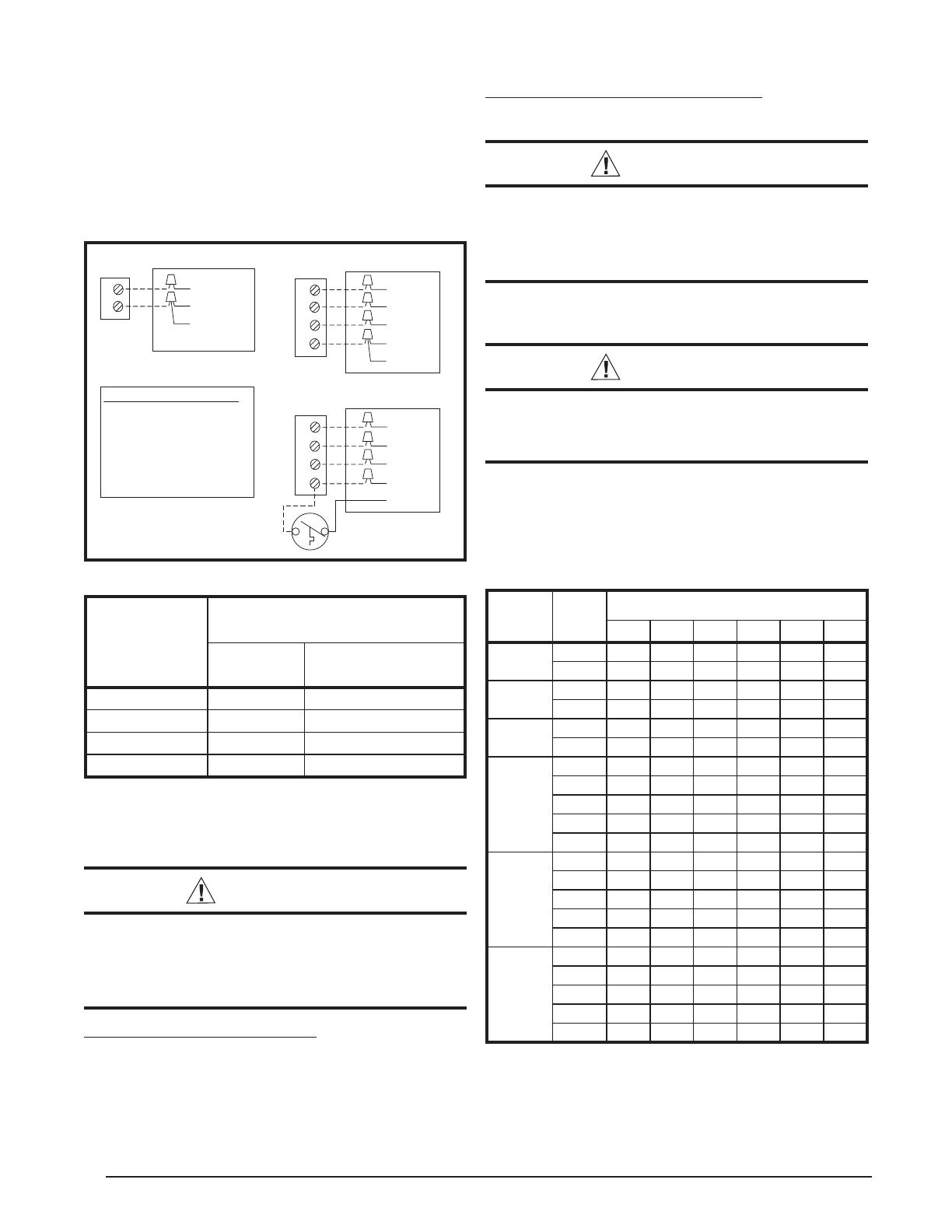
Figure 9. Low Voltage Connections
RED
R
YELLOW
Y
GREEN
G
BROWN
W
ORANGE
RED
R
YELLOW
Y
GREEN
G
BROWN
W
ORANGE
4 WIRE HEAT/COOL THERMOSTAT
Two Stage
Electric Heat
Single Stage Electric Heat
RED
R
YELLOW
Y
GREEN
BROWN
2 WIRE COOLING THERMOSTAT
CONTROL WIRE LEGEND:
GREEN - Blower Relay
RED - Transformer (24V)
YELLOW - Cooling 1st Stage
BROWN - Heating 1st Stage
ORANGE - Heating 2nd Stage
Table 3. Thermostat Wire Gauge
Thermostat
Wire Gauge
Recommended T-Stat Wire
Length (Unit to T-Stat)
2-Wire
(Heating)
5-Wire
(Heating/Cooling)
24 55 25
22 90 45
20 140 70
18 225 110
Blower Speed
For optimum system performance and comfort, it may be
necessary to change the factory speed setting.
WARNING:
To avoid electric shock, personal injury, or death,
turn off the electric power at the disconnect
or the main service panel before making any
electrical connections.
Standard Motor (2, 2.5 and 3 Ton)
1. Disconnect all electrical power to the unit and remove
the service panel.
2. Place the desired blower speed lead on the COM
terminal. Use another wire tie (fi eld supplied) to bundle
the remaining motor leads.
Table 4. Motor Lead Connection
Model
Number
P5RD
Speed
Tap
External Static Pressure (in. WC)
0.1 0.2 0.3 0.4 0.5 0.6
024K
Low* 847 808 770 726 664 562
High** 1,104 1,114 1,064 1,010 935 846
030K
Low
847 808 770 726 664 562
High 1,104 1,114 1,064 1,010 935 846
036K
Low
1,323 1,285 1,246 1,196 1,146 1,087
High 1,559 1,525 1,486 1,430 1,381 1,315
042K
Tap T1 1,100 900 750 650 580 520
Tap T2 1,170 1,080 1,000 620 900 860
Tap T3 1,220 1,180 1,140 1,100 1,070 1,020
Tap T4* 1,370 1,333 1,300 1,260 1,230 1,180
Tap T5** 1,410 1,340 1,450 1,320 1,280 1,240
048K
Tap T1 1,380 1,360 1,340 1,300 1,260 1,240
Tap T2** 1,530 1,480 1,450 1,420 1,390 1,350
Tap T3* 1,570 1,540 1,500 1,475 1,440 1,405
Tap T4 1,740 1,700 1,650 1,630 1,600 1,560
Tap T5 2,130 2,080 1,970 1,890 1,850 1,800
060K
Tap T1 1,380 1,360 1,340 1,300 1,260 1,240
Tap T2** 1,530 1,480 1,450 1,420 1,390 1,350
Tap T3 1,570 1,540 1,500 1,475 1,440 1,405
Tap T4* 1,740 1,700 1,650 1,630 1,600 1,560
Tap T5 2,130 2,080 1,970 1,890 1,850 1,800
NOTE: Airfl ow performance is with a dry coil
* Denotes factory set cooling speed
** Denotes factory set electric heating speed
Factory set cooling and electric heating speed
11
START UP & ADJUSTMENTS
Pre-Start Checklist
The following check list should be observed prior to
starting the unit.
Verify the unit is level and allows proper condensate
drainage.
Verify the outdoor coil and top of the unit are free from
obstructions and debris, and all equipment access/
control panels are in place. Unit must be installed with
the proper clearances as listed in Figure 2 (page 5).
Verify that the duct work is sealed to prevent air leakage.
Verify that the line voltage power leads are securely
connected and the unit is properly grounded. Check
the condenser fan to make sure it turns freely.
Verify the thermostat is wired correctly and installed
in a proper location. Make sure the low voltage wires
are securely connected to the correct leads on the low
voltage terminal strip.
Verify that the power supply branch circuit overcurrent
protection is sized properly.
Start-Up Procedure
The control circuit consists of an anti-short cycle timer
that will not let the compressor re-start before three (3)
minutes have elapsed.
1. Set the system mode to OFF and the temperature
mode to its highest setting.
2. Turn power on at the disconnect switch.
3. Set the system mode to ON or COOL.
4. Set the temperature mode below room temperature.
Verify that the indoor blower, outdoor fan, and
compressor energize and the cooling function starts.
5. Verify the discharge air grilles are adjusted and the
system air is balanced.
6. Verify the duct work has no air leaks.
7. Verify the condensate drain is installed correctly and
functions properly.
8. Set the temperature mode above room temperature.
The unit should stop.
9. Instruct the homeowner on unit and thermostat operation
and fi lter servicing.
System Cooling
Set the thermostat’s system mode to COOL and the
fan mode to AUTO. Change the thermostat temperature
selector below the existing room temperature. Allow the
cooling system to operate for several minutes and check
for the discharge of cool air at the supply registers.
Short Cycle Protection
The control circuit is equipped with a time-delay feature
for protection against short cycling. With the system
operating in the cooling mode, gradually raise the
thermostat temperature setting until the whole system de-
energizes. Immediately lower the thermostat temperature
to the original setting and verify that the indoor blower is
energized. After approximately 3 minutes the compressor
and the outdoor fan will energize.
Emergency Heat
(Available only when Electric heat is supplied) Set the
thermostat’s system mode to EM HT and the fan mode
to either AUTO (intermittent air) or to ON (continuous air).
Change the thermostat’s temperature selector above the
existing room temperature and check the following:
1. The thermostat auxiliary heat light (RED) should be
on.
2. The compressor and fan should not run; low voltage
circuit remains energized.
3. The blower will run according to the thermostat’s fan
mode setting.
Adjustment of Refrigerant Charge:
CAUTION:
This air conditioner contains liquid and gaseous
refrigerant under pressure. Adjustment of
refrigerant charge should only be attempted
by qualifi ed, trained personnel thoroughly
familiar with the equipment and safe responsible
refrigerant handling procedures. Under no
circumstances should the homeowner attempt
to install and/or service this equipment. Failure
to comply with this warning could result in
equipment damage, personal injury, or death.
To achieve rated capacity and effi ciency the compressor
must be exposed to refrigerant for at least 24 hours
prior to running and then the compressor must be run
for a minimum of 12 hours.
The refrigerant charge can be checked and adjusted
through the service ports provided external to the
unit. Use only gage line sets which have a “Schrader”
depression device present to actuate the valve.
Charging an R-410A Unit in AC Mode with Outdoor
Temperatures Above 55° F
1. With the system operating at steady-state, measure
the liquid refrigerant pressure in psig at the service
valve.
2. Measure the liquid refrigerant temperature (° F) at the
service valve.
3. For the temperature measured, determine the required
liquid refrigerant pressure from the appropriate charging
charts (Table 6 - 11, pages 16 - 18).
If the pressure measured in step 1 is greater than
the required liquid refrigerant pressure determined in
step 4, then there is too much charge in the system.
Remove refrigerant and repeat steps 1 through 3 until
the system is correctly charged.
If the pressure measured in step 1 is less than the
required liquid refrigerant pressure determined in
step 4, then there is too little charge in the system.
Add refrigerant and repeat steps 1 through 3 until the
system is correctly charged.
12
COMPONENT FUNCTIONS
High Pressure Switch (HPS)
A high-pressure switch is factory-installed and located in
the liquid line internal to the unit. The switch is designed
to protect the system when very high pressures occur
during abnormal conditions. Under normal conditions,
the switch is closed. If the liquid pressure rises above 575
psig, the switch will open and de-energize the unit. The
switch will close again once the liquid pressure decreases
to 460 psig. Please note that the switch interrupts the
thermostat inputs to the unit. When the switch opens and
then closes, there will be a 5 minute short cycling delay
before the unit will energize.
Low Pressure Switch (LPS)
A low-pressure switch is factory-installed and located in
the suction line internal to the unit. The switch is designed
to protect the compressor from a loss of charge. Under
normal conditions, the switch is closed. If the suction
pressure falls below 5 psig, the switch will open and de-
energize the unit. The switch will close again once the
suction pressure increases above 20 psig. Please note
that the switch interrupts the thermostat inputs to the unit.
When the switch opens and then closes, there will be a
5 minute short cycling delay before the unit will energize.
REPLACEMENT PARTS
Replacement parts are available through all Nordyne
distributors.
Please have the complete model and serial number of the unit
when ordering replacement parts.
ELECTRICAL:
Capacitors Temperature Limit Switches
Compressors Thermostats
Contactors Time Delay Relays
Pressure Switches Transformers
Relays
MOTORS:
Blower Motor
Fan Motor
COMPONENTS:
Blower Assembly Fan Grille
Cabinet Panels Filter/Driers
Expansion Valves
AIR CONDITIONER MAINTENANCE
WARNING:
To prevent electrical shock, personal injury,
or death, disconnect all electrical power to
the unit before performing any maintenance
or service. The unit may have more than one
electrical supply.
Proper maintenance is important to achieve optimum
performance from the air conditioner. The ability to properly
perform maintenance on this equipment requires certain
mechanical skills and tools. If you do not possess these
skills, contact your dealer for maintenance. Consult your
local dealer about the availability of maintenance contracts.
Routine maintenance should include the following:
Inspect and clean or replace air fi lters at the beginning
of each heating and cooling season, or more frequently
if required.
Inspect the condensate drain and outdoor coil at the
beginning of each cooling season. Remove any debris.
Clean the outdoor coil and louvers as necessary using
a mild detergent and water. Rinse thoroughly with water.
Inspect the electrical connections for tightness at the
beginning of each heating and cooling season. Service
as necessary.
CAUTION:
The unit should never be operated without a
lter in the return air system. Replace disposable
lters with the same type and size.
Do not attempt to add additional oil to motors unequipped
with oil tubes. The compressor is hermetically sealed
at the factory and does not require lubrication.
13
L
W
Top View
FIGURES AND TABLES
18.01
Electric Heater Power Supply
Power Supply
Low Voltage Supply
Control
Access
Panel
Blower Access Panel
H
17.86
15.36
10.10
3/4" NPT
Drain Connection
1"
12.13
1.38
3.2
3.2 5.29
9.15
9.04
17.50
14" diameter
Return Duct
Opening
12" diameter
Supply Duct
Opening
3.0
5.5
1"
3.15
A
B
Back (Duct) View
Side View
Model No.
GP5RD-
Length
-L-
Width
W
Height
-H-
-A- -B-
Return Diameter
(in)
Supply Diameter
(in)
024K 49 35 30.2 35.02 2.48
14 12
030K 49 35 30.2 35.02 2.48
14 12
036K 49 35 30.2 35.02 2.48
14 12
042K 49 35 30.2 35.02 2.48
14 12
048K 49 35 30.2 35.02 2.48
14 12
060K 49 35 34.2 35.02 2.48
14 12
Table 5. P5RD Physical Data
Figure 10. Unit Dimensions
14
3 AMP
FUSE
COMPRESSOR
OUTDOOR
FAN MOTOR
BLOWER
MOTOR
DUAL
CAPACITOR
S
R
C
L2 L1
T2 T1
COMPRESSOR
CONTACTOR
24V
COM
HIGH PRESSURE
SWITCH
240V
LOW
PRESSURE
SWITCH
(SELECT
MODELS
ONLY)
S
R
C
N
G
L
C
5
4
3
2
1
9
8
7
6
5
4
3
2
1
9
8
7
6
COM NO
NC
THERMOSTAT
THERMOSTAT
F
H
C
LOAD RELAY
TRANSFORMER
BLUE
ORANGE
RED
BLACK
BLACK
YELLOW
THERMOSTAT
YELLOW
YELLOW/BLACK
YELLOW
YELLOW/BLACK
YELLOW
1. Couper le courant avant de faire letretien.
2. Employez uniquement des conducteurs en cuivre.
3. Ne convient pas aux installations de plus de 150 V a la terre.
FIELD WIRING
LEGEND:
LOW VOLTAGE
HIGH VOLTAGE
Packaged Air Conditioner - Single Phase
NOTES:
1. Disconnect all power before servicing.
2. For supply connections use copper conductors only.
3. Not suitable on systems that exceed 150 V to ground.
4. For replacement wires use conductors suitable for 105° C.
5. See installation instructions for blower motor airflow settings
YELLOW
RED
GREEN
BROWN
ORANGE
RED
RED
RED
RED
RED
BLACK
BLACK
BLACK
WHITE
WHITE
WHITE
WHITE
ORANGE
GREEN/YELLOW
GREY
BLUE
YELLOW
RED
WD # 7108060
Figure 11. Wiring Diagram - P5RD with ECM Motor
ELECTRICAL INFORMATION
15
3 AMP
FUSE
COMPRESSOR
DUAL
CAPACITOR
S
R
C
L2 L1
T2 T1
COMPRESSOR
CONTACTOR
COM
240V
LOW PRESSURE SWITCH
(SELECT MODELS ONLY)
5
4
3
2
1
9
8
7
6
5
4
3
2
1
9
8
7
6
THERMOSTAT
THERMOSTAT
THERMOSTAT
F
H
C
TRANSFORMER
RED
BLACK
XFMR-R
XFMR-C
R
C
G
SPEEDUP
COM
N.O. N.C.
OUTDOOR
FAN MOTO R
S
R
C
BLUE
ORANGE
BLACK
H
L
C
CAPACITOR
BROWN
BROWN
BLACK
RELAY
CONTROL
BOARD
WHITE
BLOWER
MOTOR
RED
HIGH PRESSURE
SWITCH
YELLOW
YELLOW/BLACK
YELLOW/BLACK
YELLOW
YELLOW
1. Couper le courant avant de faire letretien.
2. Employez uniquement des conducteurs en cuivre.
3. Ne convient pas aux installations de plus de 150 V a la terre.
FIELD WIRING
LEGEND:
LOW VOLTAGE
HIGH VOLTAGE
Packaged Air Conditioner - Single Phase
NOTES:
1. Disconnect all power before servicing.
2. For supply connections use copper conductors only.
3. Not suitable on systems that exceed 150 V to ground.
4. For replacement wires use conductors suitable for 105° C.
5. See installation instructions for blower motor airflow settings.
RED
RED
BLACK
WHITE
WHITE
BLUE
YELLOW
RED
GREEN
YELLOW
ORANGE
BROWN
BLACK
GREY
YELLOW
RED
WHITE
RED
RED
YELLOW
Figure 12. Wiring Diagram - P5RD with PSC Motor
WD # 7108260
16
REFRIGERANT CHARGING CHARTS
Shaded boxes indicate fl ooded conditions.
Rated design values. The suction pressure will vary from design value if outdoor air fl ow, entering dry
bulb, or entering wet bulb temperatures vary.
1. All pressures are listed psig and all temperatures in °F
2. Discharge temperatures greater than charted values indicate an undercharged system.
Refrigerant Charging Chart Legend:
Suct.
Press.
OUTDOOR TEMPERATURE (°F)
70 75 80 85 90 95 100 105
Liq.
Press.
Dis.
Temp.
Liq.
Press.
Dis.
Temp.
Liq.
Press.
Dis.
Temp.
Liq.
Press.
Dis.
Temp.
Liq.
Press.
Dis.
Temp.
Liq.
Press.
Dis.
Temp.
Liq.
Press.
Dis.
Temp.
Liq.
Press.
Dis.
Temp.
137 254 133
139
257 139
276 135
141 259 144
279 140
299 138
143
265 142
281 146
301 142
321 140
145 268 144
286 145
303 147
323 145
343 143
147 290 148
308 149
325 149
345 147
365 145
149 312 152
330 152
347 151
367 149
388 148
151 333 156
351 155
369 154
390 152
410 151
153 337 159 355 159
373 158
392 156
412 155
155 358 163 376 162
395 160
414 159
157 380 166 398 164
416 163
159 401 169 420 167
161 423 171
163
Table 7. Charging Chart for 2.5 Ton Units
Suct.
Press.
OUTDOOR TEMPERATURE (°F)
70 75 80 85 90 95 100 105
Liquid
Press.
Dis
Temp.
Liq.
Press.
Dis.
Temp.
Liq.
Press.
Dis.
Temp.
Liq.
Press.
Dis.
Temp.
Liq.
Press.
Dis.
Temp.
Liq.
Press.
Dis.
Temp.
Liq.
Press.
Dis.
Temp.
Liq.
Press.
Dis.
Temp.
134 243 132
136
245 137
265 134
138 247 143
267 139
287 136
140
253 141
269 144
289 140
309 138
142 256 144
274 144
291 145
311 142
331 140
144 278 147
296 147
313 147
333 144
353 142
146 299 151
317 150
335 148
355 146
375 144
148 321 153
339 152
357 150
377 148
397 147
150 324 157 342 156
360 154
379 152
399 150
152 346 160 364 158
382 156
401 154
154 367 163 385 161
404 158
156 389 165 407 163
158 410 167
160
Table 6. Charging Chart for 2 Ton Units
17
REFRIGERANT CHARGING CHARTS - CONTINUED
Suct.
Press.
OUTDOOR TEMPERATURE (°F)
70 75 80 85 90 95 100 105
Liq.
Press.
Dis.
Temp.
Liq.
Press.
Dis.
Temp.
Liq.
Press.
Dis.
Temp.
Liq.
Press.
Dis.
Temp.
Liq.
Press.
Dis.
Temp.
Liq.
Press.
Dis.
Temp.
Liq.
Press.
Dis.
Temp.
Liq.
Press.
Dis.
Temp.
132 270 149
134
273 155
296 151
136 275 160
298 156
322 153
138
280 159
300 161
324 158
347 156
140 284 161
305 162
326 163
349 160
373 158
142 309 165
331 165
352 165
375 163
399 161
144 334 169
356 168
377 167
401 165
424 163
146 359 172
381 171
403 169
426 167
450 166
148 363 175 384 175
406 173
428 171
452 170
150 388 178 410 177
431 176
454 174
152 413 181 435 180
457 178
154 438 184 460 182
156 463 187
158
Table 8. Charging Chart for 3 Ton Units
Suct.
Press.
OUTDOOR TEMPERATURE (°F)
70 75 80 85 90 95 100 105
Liq.
Press.
Dis.
Temp.
Liq.
Press.
Dis.
Temp.
Liq.
Press.
Dis.
Temp.
Liq.
Press.
Dis.
Temp.
Liq.
Press.
Dis.
Temp.
Liq.
Press.
Dis.
Temp.
Liq.
Press.
Dis.
Temp.
Liq.
Press.
Dis.
Temp.
131 269 138
133
272 143
293 143
135 274 148
295 148
317 147
137
278 151
298 153
319 152
341 152
139 281 153
301 156
321 157
343 157
365 157
141 305 159
325 160
345 161
367 161
389 161
143 329 164
349 165
369 165
391 166
413 166
145 352 168
373 169
393 170
415 170
437 171
147 356 172 376 173
396 174
417 174
439 175
149 379 177 400 178
420 178
441 178
151 403 182 424 183
444 183
153 427 187 447 187
155 451 192
157
Table 9. Charging Chart for 3.5 Ton Units
Shaded boxes indicate fl ooded conditions.
Rated design values. The suction pressure will vary from design value if outdoor air fl ow, entering dry
bulb, or entering wet bulb temperatures vary.
1. All pressures are listed psig and all temperatures in °F
2. Discharge temperatures greater than charted values indicate an undercharged system.
Refrigerant Charging Chart Legend:
18
Suct.
Press.
OUTDOOR TEMPERATURE (°F)
70 75 80 85 90 95 100 105
Liq.
Press.
Dis.
Temp.
Liq.
Press.
Dis.
Temp.
Liq.
Press.
Dis.
Temp.
Liq.
Press.
Dis.
Temp.
Liq.
Press.
Dis.
Temp.
Liq.
Press.
Dis.
Temp.
Liq.
Press.
Dis.
Temp.
Liq.
Press.
Dis.
Temp.
129 279 140
131
281 145
304 144
133 283 150
306 149
329 148
135
287 152
308 154
331 153
353 153
137 291 155
312 157
333 158
356 157
378 157
139 315 160
337 161
358 162
380 161
403 161
141 340 164
361 165
382 166
405 165
428 166
143 365 169
386 169
407 170
430 170
453 170
145 368 173 389 173
411 174
432 174
455 174
147 393 177 414 178
435 178
457 178
149 417 182 439 182
460 182
151 442 186 463 186
153 467 191
155
Table 11. Charging Chart for 5 Ton Units
Suct.
Press.
OUTDOOR TEMPERATURE (°F)
70 75 80 85 90 95 100 105
Liq.
Press.
Dis.
Temp.
Liq.
Press.
Dis.
Temp.
Liq.
Press.
Dis.
Temp.
Liq.
Press.
Dis.
Temp.
Liq.
Press.
Dis.
Temp.
Liq.
Press.
Dis.
Temp.
Liq.
Press.
Dis.
Temp.
Liq.
Press.
Dis.
Temp.
131 281 142
133
283 147
306 146
135 285 152
308 151
330 151
137
289 155
310 156
332 155
355 155
139 292 158
313 159
334 160
357 160
379 160
141 317 162
338 164
359 164
381 164
404 164
143 341 167
362 168
384 168
406 168
429 168
145 366 172
387 172
408 172
431 172
453 173
147 369 175 390 176
412 176
433 176
455 176
149 394 180 415 180
436 181
457 180
151 418 185 439 185
461 185
153 443 189 464 189
155 467 194
157
Table 10. Charging Chart for 4 Ton Units
REFRIGERANT CHARGING CHARTS - CONTINUED
Shaded boxes indicate fl ooded conditions.
Rated design values. The suction pressure will vary from design value if outdoor air fl ow, entering dry
bulb, or entering wet bulb temperatures vary.
1. All pressures are listed psig and all temperatures in °F
2. Discharge temperatures greater than charted values indicate an undercharged system.
Refrigerant Charging Chart Legend:
19
INSTALLER
PLEASE LEAVE THESE INSTALLATION
INSTRUCTIONS WITH THE HOMEOWNER.
7091550 (Replaces 7089010)
Specifi cations and illustrations subject to change
without notice or incurring obligations.
Printed in U.S.A. (01/10)
O’Fallon, MO
7091550
¢7091552¤
INSTALLATION / PERFORMANCE CHECK LIST
REFRIGERATION SYSTEM:
Was unit given 24 hr warm up period
for crankcase heaters?
YES NO
Stage-1 Liquid Pressure (high side) ________________________
Stage-1 Suction Pressure (low side) ________________________
Has the owner’s information been
reviewed with the customer?
YES NO
Has the Literature Package been left
with the unit?
YES NO
INSTALLATION ADDRESS:
CITY ________________________ STATE ________________
UNIT MODEL # ________________________________________
UNIT SERIAL # ________________________________________
Unit Installed Minimum clearances per
Figure 2 (page 5)?
YES NO
INSTALLER NAME:
CITY _______________________ STATE ________________
ELECTRICAL SYSTEM:
Electrical connections tight? YES NO
Line voltage polarity correct? YES NO
Rated Voltage: ______________________________________ VOLTS
L1-L2 Volts: ________________________________________ VOLTS
L1-L3 Volts: ________________________________________ VOLTS
L2-L3 Volts: ________________________________________ VOLTS
Avg. Volts: _________________________________________ VOLTS
Max. deviation of voltage
from avg. volts: ______________________________________ VOLTS
% Volt imbalance: ___________________________________ VOLTS
Blower Motor HP: ________ Sheave Setting ______________# Turns
Has the thermostat been calibrated? YES NO
Is the thermostat level? YES NO
Is the heat anticipator setting correct?
(If Applicable)
YES NO
1 / 1

Broan GP5RD Installation guide

Category
Heat pumps
Type
Installation guide
This manual is also suitable for

Ask a question and I''ll find the answer in the document

Finding information in a document is now easier with AI

Ask the document