
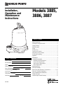
Installation,
Operation and
Maintenance
Instructions
Models 3885,
3886, 3887
IM059R02
Table of Contents
SUBJECT PAGE
Safety Instructions................................................................. 2
Description and Specifications ............................................. 2
Lifting of Pump ..................................................................... 2
Sliderail System .................................................................... 2
Piping..................................................................................... 2
Access Doors......................................................................... 3
Liquid Level Controls ........................................................... 3
Pump Motor Control Panels.................................................. 3
Wiring and Grounding .......................................................... 3
Operation ............................................................................... 4
Maintenance .......................................................................... 4
Disassembly/Assembly ......................................................... 5
Mechanical Seal Replacement .......................................... 5
Power Cable Replacement ................................................ 5
Start Capacitor Replacement............................................. 6
Motor Replacement ........................................................... 6
Engineering Data................................................................... 7
Sectional Assembly .............................................................. 8
Repair Parts and Materials of Construction....................9, 10
Typical 2" Slide Rail Installation........................................ 11
Typical Plumbing and Installation ...................................... 11
Trouble Shooting................................................................. 12
Goulds Pumps Limited Warranty ....................................... 12
Owner’s Information
Model Number:
Serial Number:
Dealer:
Dealer’s Phone No.
Date of Purchase: Installation:
Current Readings at Startup:
Single Phase:
Three Phase – 1st Phase:
2nd Phase: 3rd Phase:

2
WARNING
Hazardous voltage
can shock, burn or
cause death.
DESCRIPTION AND SPECIFICATIONS
The Model 3885 is a 2" NPT discharge,
3
⁄4" (19 mm) solids
handling, submersible effluent pump. The Model 3886 is
a 2" (50 mm) solids handling, submersible sewage pump.
The Model 3887 is a 2" flanged (standard) 3" flange
(optional) discharge, 2" (50 mm) solids handling,
submersible sewage pump.
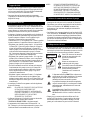
Lifting of Pump
DO NOT LIFT, CARRY OR HANG
PUMP BY THE ELECTRICAL
CABLES. DAMAGE TO THE
ELECTRICAL CABLES CAN CAUSE
SHOCK, BURNS OR DEATH.
• Lift the pump with an adequately sized chain or cable
attached to the lifting handle (458). DO NOT damage
electrical cables while raising and lowering unit.
Sliderail System
• The OPTIONAL Goulds Model A10-20 sliderail system is
recommended for proper installation.
NOTICE: FOLLOW THE INSTALLATION AND
OPERATION INSTRUCTIONS PROVIDED
WITH THE SLIDERAIL SYSTEM.
• Installation of the sliderail system should locate the pump
opposite the influent opening, preventing stagnate areas
where solids can settle.
• The pit floor MUST be flat under the sliderail base and
have sufficient loading capacity to support the entire
weight of the assembly, including the sliderail base,
sliderail guide, pump and all assorted piping.
Piping
• Discharge piping should be no smaller than 2" (51 mm)
diameter and kept as short as possible, avoiding
unnecessary fittings to minimize friction losses.
• Install an adequately sized check valve (suitable for
handling
3
⁄4" (19 mm) solids for effluent applications and
2" (50 mm) solids for sewage applications) in the
discharge pipe to prevent backflow. Follow the check
valve manufacturer’s installation instructions.
• Install an adequately sized gate valve ABOVE the check
valve for pump, plumbing and check valve maintenance.
• To deter air locking, drill a
3
⁄16" (4.8 mm) hole, 2"
(50.8 mm) beyond the pump discharge connection.
• All piping must be adequately supported, so as not to
impart any piping strain or loads on the pump.
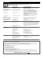
SAFETY INSTRUCTIONS
TO AVOID SERIOUS OR FATAL PERSONAL
INJURY OR MAJOR PROPERTY DAMAGE, READ
AND FOLLOW ALL SAFETY INSTRUCTIONS IN
MANUAL AND ON PUMP.
THIS MANUAL IS INTENDED TO ASSIST IN THE
INSTALLATION AND OPERATION OF THIS UNIT
AND MUST BE KEPT WITH THE PUMP.
This is a SAFETY ALERT SYMBOL.
When you see this symbol on the pump or
in the manual, look for one of the follow-
ing signal words and be alert to the
potential for personal injury or property
damage.
Warns of hazards that WILL cause serious
personal injury, death or major property
damage.
Warns of hazards that CAN cause serious
personal injury, death or major property
damage.
Warns of hazards that CAN cause personal
injury or property damage.
NOTICE:INDICATES SPECIAL INSTRUCTIONS
WHICH AREVERY IMPORTANT AND
MUST BE FOLLOWED.
THOROUGHLY REVIEW ALL INSTRUCTIONS
AND WARNINGS PRIOR TO PERFORMING ANY
WORK ON THIS PUMP.
MAINTAIN ALL SAFETY DECALS.
UNIT NOT DESIGNED FOR USE
WITH HAZARDOUS LIQUIDS OR
FLAMMABLE GASES. THESE
FLUIDS MAY BE PRESENT IN
CONTAINMENT AREAS.
NOTICE: INSPECT UNIT FOR DAMAGE AND
REPORT ALL DAMAGE TO THE CARRIER
OR DEALER IMMEDIATELY.
DANGER
WARNING
CAUTION
WARNING
Hazardous fluids
can cause fire,
burns or death.

3
NOTICE:DURING PUMP OPERATION, INSURE THAT
THE LIQUID LEVEL DOES NOT DROP
BELOW THE PUMP MOTOR FOR
EXTENDED PERIODS. THIS CAN CAUSE
THE PUMP MOTOR TO OVERHEAT,
CAUSING MOTOR DAMAGE AND
VOIDING THE WARRANTY.
Pump Motor Control Panels
• Control panels shall be in accordance with local and
National Electrical Code requirements.
• Single phase installations shall be equipped with a Goulds’
“SES” or “A” Series panel, or AS A MINIMUM, a
control panel with a properly sized magnetic contactor and
a disconnect switch.
• Three phase installations shall be equipped with a Goulds’
“SES” or “A” Series panel, or AS A MINIMUM with a 3
pole circuit breaker, an across the line magnetic starter
NEMA rated for the appropriate horsepower, ambient
compensated Quick Trip Class 10 overload relays.
Wiring and Grounding
• Use only stranded copper wire to motor and ground. The
ground wire must be at least as large as the wires to the
motor. Wires should be color coded for ease of
maintenance.
Install, ground and wire
according to local and National
Electrical Code requirements.
Install an all leg disconnect
switch near the pump.
Disconnect and lockout electrical
power before installing or
servicing pump.
Electrical supply MUST match pump’s nameplate
specifications. Incorrect voltage can cause fire,
damage motor and voids warranty.
Single phase motors are equipped with automatic
thermal protectors which open the motor’s
electrical circuit when an overload exists. This
can cause the pump to start unexpectedly and
without warning.
Some models are equipped with a 3-prong
grounded plug and MUST be used in a grounded
3-wire receptacle. DO NOT modify the plug or
remove the ground prong.
• Where cables must be spliced or connected to the motor
leads, splices MUST be water tight. Commercially
available potting or heat shrink kits may be used, if
allowed by local or federal regulations.
WARNING
Hazardous voltage
can shock, burn or
cause death.
Access Doors
• Access doors can be single or double leaf design. Doors
should include a lifting handle and a lock provision for
tamper resistant operation. Standard and heavy duty steel
or aluminum doors are available.
• The pit access door must be of sufficient size to allow for
inspection, maintenance and crane or hoist service.
Liquid Level Controls
• Single float operation can be used on
1
⁄3 and
1
⁄2 HP models.
Mounting of the float switch must be checked by the
installer to insure proper turn on and turn off. The pump
may be plugged directly into the piggy back style plug
located on the cord of the float switch.
• The recommended float operation sequence used with a
control panel requires a three or four float system. In the
three float system, the floats are designated SW-1 for the
bottom float, SW-2 for the middle float and SW-3 for the
top float. In a four float system the fourth float is
designated SW-4.
• Simplex Control – The rising liquid level raises float
SW-2, turning on the pump. When the liquid level falls
sufficiently, SW-1 will turn the pump off. If the influent
is excessive, or if the pump fails to operate correctly,
SW-3 will activate an alarm, which will remain on until
manually reset.
• Duplex Control – The duplex control will alternate the
two pumps, causing the lead pump to change at each
system cycle. When equipped with three floats, the
system will cycle the same as the simplex control,
described above, except that the SW-1 will cause the
lead pump to alternate.
• If the influent is excessive, or if the lead pump fails to
operate correctly, the rising level will activate SW-3,
turning on the lag pump and the alarm. As before the
alarm must be manually reset.
• Four Float Control – The four float system operates the
same as the duplex control system, except that float
SW-3 will not turn on the alarm. In this system SW-4
turns on the alarm, which again must be manually reset.
• Several different float controls are available from the
Goulds Catalog.
NOTICE:POSITION THE FLOATS SO THAT THEY
DO NOT SNAG OR TANGLE ON THE PUMP,
DISCHARGE PIPING, OR OTHER
EQUIPMENT.
• The lower most float turns the unit off and should be set as
shown in the “TYPICAL PLUMBING and
INSTALLATION” drawing provided in this manual.
• Increasing the distance between the SW-1 and SW-2 floats
lengthens the running time. One (1) minute is the
minimum recommended pump cycle time.

4
WARNING
Biohazard can
cause serious
personal injury.
WARNING
Hazardous
voltage
• If the three phase motor(s) rotation is backwards, reverse
any two pump power cable leads at the pump control
panel.
MOTOR OVERHEAT/OVER
CURRENT SENSING DEVICES
AUTOMATICALLY RESTART THE
MOTOR UNEXPECTEDLY AND
WITHOUT WARNING. THIS CAN
CAUSE SEVERE PERSONAL
INJURY.
• After installing the pump into the containment area, with
adequate submergence, open the discharge valve fully.
Start the unit using manual controls. If flow is appreciably
less than rated performance, pump may be air bound. To
expel trapped air, jog the unit several times, using the
manual controls.
• Have a qualified electrician take current measurements on
the single or all three phases. Record these readings in the
space provided in the “OWNER’S INFORMATION”
section of this manual for future reference.
• The unit is now ready for normal operation. Place the
controls in the automatic position.
Maintenance
FAILURE TO DISCONNECT AND
LOCKOUT ELECTRICAL POWER
BEFORE ATTEMPTING ANY
MAINTENANCE CAN CAUSE
SHOCK, BURNS OR DEATH.
UNIT MUST BE FLUSHED AND
DISINFECTED, INSIDE AND OUT,
PRIOR TO SERVICING.
Periodic Maintenance
NOTICE:ROUTINE PERIODIC INSPECTIONS ARE
REQUIRED AND SHOULD FOLLOW THE
FREQUENCY AND MAINTENANCE
SCHEDULE PROVIDED.
FREQUENCY REQUIRED MAINTENANCE
MONTHLY • Duplex Units – Check for even
operating times. Uneven operation
times indicate a defective unit, float
switch or control.
• Unimpeded float operation.
WARNING
Hazardous
machinery
NOTICE: FOLLOW THE SPLICE KIT
MANUFACTURER’S INSTRUCTIONS.
• Where wire splices are used, follow one of these
procedures:
• Butt join the wires using properly sized and correctly
crimped Sta-Kon™, or equivalent, connectors. Insulate
and water proof each joint using heat shrink tubing
equipped with a self contained sealer. Apply heat
evenly from a torch until adequately sealed.
OR
• Use plastic insulators and a neoprene gasket sleeve set
with properly sized and correctly crimped Sta-Kon™
connectors. Place a cap and gasket on each wire end,
center insulator body over splice, insert the sleeve into
the body as far as possible, hand tighten caps.
• In the case of multiple conductors, stagger the joints.
FAILURE TO PERMANENTLY
GROUND THE PUMP, MOTOR AND
CONTROLS BEFORE CONNECTING
TO ELECTRICAL POWER CAN
CAUSE SHOCK, BURNS OR DEATH.
Operation
• If the unit has been stored for an extended period, check
the oil level in the motor and seal chamber, to insure that
they are full, using the following procedures:
• Motor Cover – With the pump in the upright position,
remove the oil fill plug (358E), being careful that
nothing enters the motor. The oil level should be above
the top of the motor. With the correct oil fill as required.
DO NOT over fill.
• Cable Gland Assemblies – Re-torque both the power
and sensor cable glands to values given in step 10 of
“POWER CABLE REPLACEMENT”.
• Before lowering the pump(s) into the containment area,
three phase units should be jogged to insure correct
rotation. See the motor rotation arrow on the motor cover
(341). Check both pumps in a duplex operation.
NOTICE:MOTOR STARTUP TORQUE, “KICKBACK”,
WILL CAUSE THE MOTOR TO TWIST IN
THE DIRECTION OPPOSITE ROTATION.
INSURE THAT THE PUMP ASSEMBLY IS
ADEQUATELY RESTRAINED.
DO NOT PLACE HANDS IN PUMP
SUCTION WHILE CHECKING
MOTOR ROTATION. TO DO SO
WILL CAUSE SEVERE PERSONAL
INJURY.
NOTICE: DO NOT SWITCH PRIMARY POWER LEADS
COMING INTO A THREE PHASE DUPLEX
CONTROL PANEL, THIS WILL REVERSE
ROTATION OF BOTH PUMPS.
WARNING
Hazardous
voltage
!
Hazardous Machinery
DANGER

5
WARNING
Biohazard can
cause serious
personal injury.
5. Remove and discard the mechanical seal and stationary
seat assembly. DO NOT damage the motor shaft or the
stationary seat bore.
6. Inspect and wipe clean the stationary seat bore.
7. To install the new stationary seat into the seal housing,
lubricate the stationary seat bore and motor shaft with
clean motor insulating oil. Using Goulds mechanical seal
installation tool (A02A013), slide the stationary seat
fully and squarely into the seal housing.
8. With a clean, lint free cloth, wipe the stationary face
clean of all lubricating oil or debris. DO NOT scratch or
otherwise damage the seal face.
9. Lubricate the inside of the rotary elastomer with clean
motor insulating oil. Using the Goulds installation tool,
slide the seal rotary assembly onto the motor shaft and
seat fully against the stationary seat. Remove the seal
installation tool.
10. Install the impeller onto the motor shaft by turning the
impeller on CLOCKWISE, tighten securely. Treat the
impeller with Loctite™ #271 and securely install. When
provided, securely install the impeller locknut.
11. Fill the motor cover with motor special insulating oil to
within
1
⁄2" (13 mm) of the seal chamber housing. Tape
drain plug with Teflon™ tape and install plug securely.
12. Reassemble casing and new casing gasket to pump
assembly by installing the four casing hex cap screws,
torquing in sequence to 35 lbs ft (47 Ν m).
NOTICE:FOLLOW THE INSTRUCTIONS PROVIDED
IN THE “WIRING AND GROUNDING” AND
“OPERATION” SECTIONS OF THE
MANUAL AFTER UNIT DISASSEMBLY,
REASSEMBLY.
POWER CABLE REPLACEMENT
1. To gain access to the motor cover screws follow steps 1
through 6 in the “MECHANICAL SEAL
REPLACEMENT” section of this manual.
2. Remove the power cable strain relief (484B) assembly
from the motor cover and slide up the cable.
3. Remove the four bearing housing socket head screws
(371C). Carefully slide the motor cover from the motor
assembly. DO NOT damage the power cable.
4. Disconnect the power cable wires from the motor
assembly (338).
5. Remove cable from motor cover, inspect and replace as
required, following the procedures provided.
NOTICE: DISCARD STRAIN RELIEF ASSEMBLY.
THEY CAN NOT BE REUSED.
6. Install new motor cable strain relief assembly onto cable,
sliding the hex gland on first, then the washer and finally
the packing. Insert the cables into the motor cover hole.
Pull an appropriate amount of cable through the motor
cover to allow for connecting the cable leads. DO NOT
tighten the strain relief gland.
WARNING
Hazardous
voltage
Disassembly/Assembly
FAILURE TO DISCONNECT AND
LOCKOUT ELECTRICAL POWER
BEFORE ATTEMPTING ANY
MAINTENANCE CAN CAUSE
SHOCK, BURNS OR DEATH.
NOTICE: FOLLOW ALL SAFETY AND LIFTING
INSTRUCTIONS PROVIDED IN THIS
MANUAL.
• Following the slide rail instructions, remove the pumping
unit from the sewage containment area.
UNIT MUST BE FLUSHED AND
DISINFECTED, INSIDE AND OUT,
PRIOR TO SERVICING.
MECHANICAL SEAL REPLACEMENT
1. Follow ALL instructions provided in the
“DISASSEMBLY” section of this manual.
2. To gain access to the pump impeller and mechanical seal
remove the four casing hex cap screws (372D). Remove
casing (100) and casing gasket (351); discard the gasket.
FAILURE TO REMOVE DRAIN
PLUG CAREFULLY CAN CAUSE
HOT OIL TO ERUPT FROM OIL
RESERVOIR CAUSING PERSONAL
INJURY OR PROPERTY DAMAGE
3. Removal of the mechanical seal assembly (387) requires
draining the special insulating oil from the motor cover.
This is accomplished by removing the drain plug and
draining the oil into an adequately sized clean receptacle.
See “ENGINEERING DATA” section for required
volume.
4. To remove the impeller (101), it may be necessary to
heat the impeller and impeller locknut (304), three phase
motors only, with a torch. Use no more heat that is
necessary, as excess heat will damage the mechanical
seal. Secure the impeller from rotation, and remove
the impeller lock nut, by turning the lock nut
COUNTERCLOCKWISE. Remove the impeller
from the motor shaft by holding the motor shaft with a
screw driver and turning the impeller COUNTER-
CLOCKWISE.
Hazardous pressure can
cause personal injury or
property damage.
CAUTION

6
START CAPACITOR REPLACEMENT
1. On single phase motors only, to gain access to the motor
start capacitor (376), follow steps 1 through 5 in the
“POWER CABLE REPLACEMENT” section of this
manual.
NOTICE: DISCARD STRAIN RELIEF ASSEMBLY.
IT CAN NOT BE REUSED.
FAILURE TO DRAIN CAPACITOR
OF STORED ELECTRICAL
CHARGE BEFORE SERVICE CAN
CAUSE A SEVERE SHOCK.
2. Remove the capacitor retaining screw and retaining
bracket from the motor assembly. Remove the two wires
from the capacitor. Discard the capacitor.
3. Connect the two motor wires to the new capacitor and
reassemble with the retaining bracket and retaining
screw, tightening securely.
4. Reassemble unit following steps 6 through 12 in the
“POWER CABLE REPLACEMENT” section of
this manual.
NOTICE: FOLLOW THE INSTRUCTIONS PROVIDED
IN THE “WIRING AND GROUNDING” AND
“OPERATION” SECTIONS OF THE
MANUAL AFTER UNIT DISASSEMBLY,
REASSEMBLY.
MOTOR REPLACEMENT
1. To gain access to the motor assembly, follow steps 1
through 5 in the “POWE R CABLE REPLACEMENT ”
section of this manual.
NOTICE: DISCARD STRAIN RELIEF ASSEMBLY.
IT CAN NOT BE REUSED.
2. Remove the four motor thru bolts and carefully pull
motor assembly from bearing housing. Further motor
service MUST be provided by a qualified motor repair
facility.
3. Insert the motor assembly into the bearing housing,
visually aligning the motor thru bolts through the lower
motor vent openings.
4. Install the four motor thru bolts, torquing to 35 lbs in
(4 Ν m).
5. To complete the assembly follow steps 6 through 12 in
the “POWER CABLE REPLACEMENT” section of
this manual.
NOTICE: FOLLOW THE INSTRUCTIONS PROVIDED
IN THE “WIRING AND GROUNDING” AND
“OPERATION” SECTIONS OF THE
MANUAL AFTER UNIT DISASSEMBLY,
REASSEMBLY
WARNING
Hazardous
voltage
7. Connect the power cable leads to the motor assembly as
follows:
• Single Phase Motors – Connect the BLACK wire to
motor terminal L
1
. Connect the WHITE wire to
motor terminal L
2
. Connect the GREEN wire to the
motor ground.
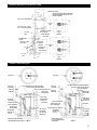
• Three Phase Motors – See Figure 1.
FAILURE TO CONNECT POWER
AND SENSOR WIRES TO
DESIGNATED WIRES CAN CAUSE
SHOCK, BURNS OR DEATH.
Figure 1
8. Wire tie the power cable to the motor assembly.
9. Slide the motor cover onto the motor assembly, while
carefully pulling the power cable out through the motor
cover hole. DO NOT damage cables. Install the four
seal housing socket head screws, torquing to 90 lbs in
(10 Ν m).
10. Install the power cable strain relief assembly torquing
the nylon bushing to 75 lbs in (8.5 Ν m) and the steel
bushing to 100 lbs in (11.3 Ν m).
11. Continue the assembly following steps 7 through 12 of
the “MECHANICAL SEAL REPLACEMENT”
section of this manual.
12. If the motor cover was replaced, it is necessary to
transfer the Goulds nameplate. Using two stainless steel
No. 2 round head metallic drive screws, install the
Goulds nameplate.
NOTICE: FOLLOW THE INSTRUCTIONS PROVIDED
IN THE “WIRING AND GROUNDING” AND
“OPERATION” SECTIONS OF THE
MANUAL AFTER UNIT DISASSEMBLY,
REASSEMBLY.
WARNING
Hazardous
voltage
1
7
2
8
3
9
6
5
4
MOTOR LEADS
L
1
L
2
L
3
G
208-230 V 3/60
7
4
MOTOR LEADS
L
1
L
2
L
3
G
460 V 3/60
8
5
9
6
1
2
3
POWER CABLE LEADS
POWER CABLE LEADS
THREE PHASE MOTOR WIRING DIAGRAM

7
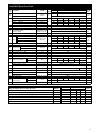
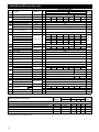
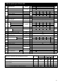
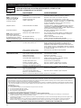
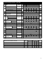
Engineering Data
Maximum Diameter Solids
3885
3
⁄4 in 19 mm
3886 and 3887 2 in 50 mm
Minimum Casing Thickness
5
⁄16 in 8 mm
Casing Corrosion Allowance
1
⁄8 in 3 mm
Minimum Working Pressure 55 psi 380 kPa
Minimum Pump Submergence – Below Top of Motor Dome 6 in 152 mm
Minimum Number of Evenly Distributed Starts per Hour 6
Maximum Operating Temperature
Continuous Operation 40° C 104° F
Intermittent Operation 60° C 140° F
Motor Cover Oil Capacity 4.5 qts. 4.3 L
ELECTRICAL DATA 3885
HP RPM Voltage
Phase
Amps
KVA Winding Resistance Power Fuse/Circuit
/Hz Code Line to Line (Ohms) Cable AWG Breaker Amps
1
⁄3 1725 115 1/60 9.4 M 1.92 16/3 15
1
⁄3 1725 230 1/60 4.7 N 7.58 16/3 10
1
⁄2 3450 115 1/60 14.5 M 1.00 16/3 20
1
⁄2 3450 230 1/60 7.3 M 4.03 16/3 10
1
⁄2 3450 200 3/60 3.9 R 3.8 14/4 10
1
⁄2 3450 230/460 3/60 3.4/1.7 R 5.81/23.24 14/4 10/10
3
⁄4 3450 230 1/60 10.0 J 2.99 14/3 15
3
⁄4 3450 200 3/60 6.2 L 5.7 14/4 10
3
⁄4 3450 230/460 3/60 5.4/2.7 L 4.04/16.15 14/4 10/10
1 3450 230 1/60 12.5 J 2.09 14/3 20
1 3450 200 3/60 8.1 M 2.6 14/4 10
1 3450 230/460 3/60 7.0/3.5 L 4.04/16.15 14/4 10/10
1
1
⁄2 3450 230 1/60 15.0 H 1.16 14/3 20
1
1
⁄2 3450 200 3/60 10.6 K 1.9 14/4 15
1
1
⁄2 3450 230/460 3/60 9.2/4.6 K 2.87/11.46 14/4 15/10
2 3450 230 1/60 18.0 F M-1.1/S-2.2 14/3 20
2 3450 200-230/460 3/60 12.0-11.6/5.8 K 1.66/6.62 14/4 15/10
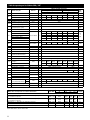
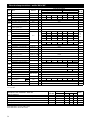
ELECTRICAL DATA 3886 AND 3887BF
1
⁄3 1725 115 1/60 9.8 M 1.92 16/3 15
1
⁄3 1725 230 1/60 4.9 N 7.58 16/3 10
1
⁄2 1725 115 1/60 14.5 N 1.6 16/3 20
1
⁄2 1725 230 1/60 7.3 K 6.4 16/3 10
1
⁄2 1725 200 3/60 3.8 K 6.55 14/4 10
1
⁄2 1725 230/460 3/60 3.3/1.7 K 9.9/39.4 14/4 10/10
3
⁄4 1725 230 1/60 9.4 J 5.9 14/3 15
3
⁄4 1725 200 3/60 4.1 H 4.3 14/4 10
3
⁄4 1725 230/460 3/60 3.6/1.8 J 5.6/22.4 14/4 10/10
1 1725 230 1/60 12.3 H 2.6 14/3 20
1 1725 200 3/60 6.0 H 4.3 14/4 10
1 1725 230/460 3/60 5.8/2.9 J 5.6/22.4 14/4 10/10
ELECTRICAL DATA 3887BHF
1
⁄3 1725 115 1/60 12.4 M 1.00 16/3 15
1
⁄3 1725 230 1/60 6.2 M 4.03 16/3 10
1
⁄2 3450 115 1/60 14.5 M 1.00 16/3 20
1
⁄2 3450 230 1/60 7.6 M 4.03 16/3 10
1
⁄2 3450 200 3/60 4.1 R 3.8 14/4 10
1
⁄2 3450 230/460 3/60 3.6/1.8 R 5.81/23.24 14/4 10/10
3
⁄4 3450 230 1/60 9.4 J 2.99 14/3 15
3
⁄4 3450 200 3/60 6.2 L 5.7 14/4 10
3
⁄4 3450 230/460 3/60 5.4/2.7 L 4.04/16.15 14/4 10/10
1 3450 230 1/60 14.5 J 2.1 14/3 20
1 3450 200 3/60 8.6 M 2.6 14/4 10
1 3450 230/460 3/60 7.5/3.8 L 4.0/16.2 14/4 10/10
1
1
⁄2 3450 230 1/60 18.0 F M-1.1/S-2.2 14/3 20
1
1
⁄2 3450 200-230/460 3/60 10.0-9.6/4.8 K 1.66/6.62 14/4 15/10
2 3450 230 1/60 18.0 F M-1.1/S-2.2 14/3 20
2 3450 200-230/460 3/60 12.0-11.6/5.8 K 1.66/6.62 14/4 15/10

8
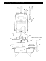
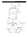
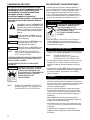
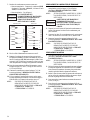
Repair Parts Diagram for Models 3885, 3886 and 3887
456 GROUP
457
376
338
372D
340
112A
412M
371C
371H
195C
351A
357
304
387
101
351
100
436
341
Note: Models 3885 and 3886 are not flanged
and therefore do not require some of the
diagramed parts.
484B
458

9
Nylon Housing
Item
No.
Part Name Material
Max. Wt.
(lbs.)
Repair Parts Order Number
1725 RPM 3450 RPM
1
⁄3 HP
1
⁄2 HP
3
⁄4 HP 1 HP 1
1
⁄2 HP 2 HP
Standard length* Optional Lengths
20' 30' 50' 100'
Power Cables
1 PH:
1
⁄3 and
1
⁄2 HP, 115 V; standard with plug, optional with bare leads SJTOW – 16/3 9K165 9K214 9K215 N/A 0.5
1 PH:
1
⁄3 and
1
⁄2 HP, 230 V; standard with plug, optional with bare leads SJTOW – 16/3 9K164 9K214 9K215 N/A 0.5
1 PH:
3
⁄4 – 1
1
⁄2 HP, 230 V with bare leads STOW – 14/3 9K163 9K216 9K161 9K217 0.9
1 PH: 1
1
⁄2 – 2 HP, 230 V with bare leads STOW – 14/3 9K266 9K267 9K268 9K269 0.9
3 PH:
1
⁄2 – 2 HP, 208–230/460 V with bare leads STOW – 14/4 9K153 9K218 9K154 9K219 1.1
Wt.
(lbs./5 ft.)
Model 3885 Power and Sensor Cables Description
Type and
AWG Size
Turbine Oil – Sunvis
932, Convis 150
7.5 lbs./
gal.
218
Insulating Oil
(
gallon
)
Gallons required
13.0
to
24.0
1
Stainless Steel
Short Ext.
100
Casing –
1
⁄3 HP “L” model only
Cast Iron 1
1K171 N/A
13.0
Casing – all others 1K170
Impeller Cast Iron 2K158 2K220 2K219 2K218 2K217 2K840 2.0
101
Impeller Bronze 2K271 2K272 2K273 2K274 2K275 2K841 2.5
Impeller – high head Cast Iron 1 N/A 2K225 HH N/A N/A 2K221HH N/A 3.5
Impeller – high head Bronze N/A 2K276 HH N/A N/A 2K277 HH N/A 4.0
112A Lower Ball Bearing Steel 1 4K132 4K384 –
112B Upper Ball Bearing Steel 1 4K132 –
4K432 (5 gallons)
1.2 gallons
304 Impeller Locknut (3 PH only) AISI 300 series SS 1 13K6 –
1 Phase, 115V 118-121R 118-1222R N/A N/A N/A N/A
338 Motor
1 Phase, 230V 118-122R 118-1223R 118-1232R 118-1233R 118-1334R 120-845R
3 Phase, 230/460 V N/A 118-1321R 118-1322R 118-1323R 118-1324R 120-8425R
3 Phase, 200 V N/A 118-1333R 118-1334R 118-1335R 118-1336R 120-8425R
340 Bearing Housing Cast Iron 1 1K167 1K332 10.0
341 Motor Cover
1 PH
Cast Iron 1
1K207 1K207 1K208 1K208 1K208 1K208
23.0
3 PH 1K208
351 Casing Gasket Composite 1 5K170 –
358E Plug – motor cover
3
⁄8" NPT Steel 1 6K3 –
371C Skt. Hd. Screw – brg. housing to motor cover AISI 300 series SS 2 13K210 –
372D Hex Screw – seal housing to casing AISI 300 series SS 4 13K186 –
376 Capacitor
(
1 PH only
)
Start
Varies 1
1K197 9K197 9K197 9K197 9K197 275470130
–
Run N/A N/A N/A N/A N/A 279342110
387
Mechanical Seal – standard Silicon Carbide 1 10K63 (John Crane Type 6) 10K71 –
Mechanical Seal – optional Tungsten Carbide 1 10K30 (John Crane Type 21) 10K72 –
412M O-ring – motor cover
BUNA-N, AS 568A-166
1 4K252 –
436 Solid State Switch N/A 294811980
456 Power cable 1 See chart below –
457
Wire nut 3 PH, 200/230 V 4 9K145 –
(power cable) 3 PH, 460 V 6 9K145 –
458 Handle Assembly AISI 300 series SS 1 4K243 –
484B
Strain Relief Assembly 1 PH
Varies
1 5K113 5K113 5K111 5K111 5K111 5K111 –
(
power cable
)
3 PH 1 N/A 5K111 –
Loctite #271 1 AL271121 –
Qty.
Reqd.
Model 3885 Repair Parts Table

10
101
218 Turbine Oil 1 4K432
Varies
Model 3886 and 3887 Repair Parts Table
484B
457
Nylon Housing
Item
No.
Part Name Material Qty.
Max. Wt.
(lbs.)
Repair Parts Order Number
1725 RPM 3450 RPM
1
⁄3 HP
1
⁄2 HP
3
⁄4 HP 1 HP 1 HP 1
1
⁄2 HP 2 HP
13.0
to
24.0
Note: The 1K168 is the casing for the 3886
1
⁄2 HP. The 1K178 is the casing for the 3887
1
⁄3 – 1 HP.
195C
7.5
lbs./gal.
AISI 300 series SS 4 13K210 –
371C
–376
387
Strain Relief Assembly
(
power cable
)
Varies
* Consult Factory
Wt.
(lbs./5 ft.)
Model 3887 Power Cables Description
Type and
AWG Size
Standard length* Optional Lengths
20' 30' 50' 100'
Power Cables
1 PH:
1
⁄3 and
1
⁄2 HP, 115 V; standard with plug, optional length with bare leads SJTOW – 16/3 9K165 9K214 9K215 N/A 0.5
1 PH:
1
⁄3 and
1
⁄2 HP, 230 V; standard with plug, optional length with bare leads SJTOW – 16/3 9K164 9K214 9K215 N/A 0.5
1 PH:
3
⁄4 – 1HP, 230 V with bare leads STOW – 14/3 9K163 9K216 9K161 9K217 0.9
1 PH: 1
1
⁄2 – 2 HP, 230 V with bare leads STOW – 14/3 9K266 9K267 9K268 9K269 0.9
3 PH:
1
⁄2 – 2 HP, 208–230/460 V with bare leads STOW – 14/4 9K153 9K218 9K154 9K219 1.1
9K197 REF#615996 1 or 624751 1 MFD 110 VAC
9K235 REF#615996 2 189/227 MFD 110 VAC
341
Cast Iron
20.0
1
1
100 Casing Cast Iron 1 1K168 for NPT 3886 1K178 for flanged 3887 1K330 16.5
Impeller Cast Iron 1 2K268 2K239 2K240 2K241 2K242 2K800 2K798 3.0
Impeller Bronze 1 2K279 2K280 2K281 2K282 2K283 2K801 2K799 3.5
112A Lower Ball Bearing Steel 1 4K132 4K384 –
112B Upper Ball Bearing (Not Shown) Steel 1 4K132 –
Discharge Flange (2" NPT STD.) Cast Iron 1 6K76 1.5
Discharge Flange (3" NPT OPT.) Cast Iron 1 A1-3 1.5
Motor Insulating Oil
(Approx. 1 Gallon Required)
304 Impeller Locknut (3 PH only) AISI 300 series SS 1 13K6 –
Motor – 1 Phase, 115V 118-121R 118-123R N/A N/A N/A N/A N/A
Motor – 1 Phase, 230V 118-122R 118-124R 118-1212R 118-1213R118-1233R 120-844R 120-845R
338 Motor – 3 Phase, 230/460 V Stainless Steel 1 N/A 118-132R 118-1304R 118-134R 118-1323R N/A N/A
Motor – 3 Phase, 200 V N/A 118-1314R 118-1316R 118-1316R 118-1335R N/A N/A
Motor – 3 Phase, 200-230/460 V N/A N/A N/A N/A N/A 120-8425R 120-8425R
340 Bearing Housing Cast Iron 1 1K167 1K332 10.0
Motor Cover – 1 Phase 1K207 1K207 1K208 1K208 1K208 1K208 1K208
Motor Cover – 3 Phase 1K208
351 Casing Gasket Composite 1 5K170 –
351A Discharge Flange Gasket Composite 1 5K150 –
357 Hex Nut –␣ discharge flange AISI 300 series SS 2 13K99
358E Plug – motor cover
3
⁄8" NPT Steel 1 6K3 –
Skt. Hd. Screw – brg. housing to
motor cover
371H
Hex Screw – discharge flange
AISI 300 series SS 2 13K153 –
372D
Hex Screw – bearing housing to casing
AISI 300 series SS 4 13K186 –
Capacitor
(
1 PH only
) Start
9K197 9K197 9K235 9K235 9K197
275469128
275470130
Capacitor
(
1 PH only
) Run
N/A N/A N/A N/A N/A N/A
279342110
Mechanical Seal – standard Silicon Carbide 1 10K63 (John Crane Type 6) 10K71 –
Mechanical Seal – optional Tungsten Carbide 1 10K30 (John Crane Type 21) 10K72 –
412M O-ring – motor cover
Nitrile
1 4K252 –
436 Solid State Switch (motor) – 1 N/A
294612982
294811980
–
456 Power Cable – 1 See chart below –
Wire Nut 3 PH, 200/230 V 4 9K145 –
Wire Nut 3 PH, 460 V 6 9K145 –
458 Handle Assembly AISI 300 series SS 1 4K243 –
1 PH 1 5K113 5K113 5K111 5K111 5K111 5K111 5K111 –
3 PH 1 N/A 5K111 –
528 Washer – discharge flange AISI 300 series SS 2 13K82 –
Loctite #271 – 1 AL27121 –

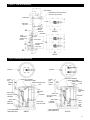
11
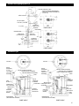
Typical 2" Slide Rail Installation
13"
8
1
⁄4"
WALL BRACKET
INTERMEDIARY WALL BRACKET FOR
WET WELLS OVER 96" DEEP.
LIFTING CABLE
GUIDE RAILS
1" DIA. PIPE
6
1
⁄4"
MAX.
DISCHARGE
COUPLING
TOP PUMP
BRACKET
VERTICAL PIPE
NIPPLES
QUICK
DISCONNECT
CHECK VALVE
BOTTOM PUMP
BRACKET
BASE PLATE
22
1
⁄2"
MAX.
3
1
⁄16"
MIN.
12"
44"
MIN.
11"
11"
11"
11"
5
1
⁄8"
Typical Plumbing and Installation
SERVICE
POLE
CONTROL
PANEL
GROUT SEAL
HIGH LEVEL ALARM
(OPTIONAL)
FLOAT SWITCH
ALARM LIGHT (OPTIONAL)
HINGED ACCESS DOOR
WRENCH OPERATED VALVE
VENT
VALVE
OPERATING
ROD
DISCHARGE
CHECK VALVE
SLIDE RAIL GUIDE
3" MIN. SUBMERGENCE
(MAINTENANCE ONLY)
6" NORMAL
OPERATION
INFLUENT
INFLUENT
ALARM LIGHT (OPTIONAL)
HINGED ACCESS DOOR
WRENCH OPERATED
VALVE
VENT
VALVE
OPERATING
ROD
DISCHARGE
CONTROL
PANEL
SERVICE
POLE
CHECK
VALVE
SLIDE
RAIL
GUIDE
GROUT SEAL
HIGH LEVEL ALARM
(OPTIONAL)
FLOAT SWITCH
3" MIN. SUBMERGENCE
(MAINTENANCE ONLY)
32"
MIN.
DUPLEX
32"
MIN.
SIMPLEX
24" MIN.
SLIDE
RAIL
SLIDE
RAIL
36"
6" NORMAL
OPERATION
DUPLEXSIMPLEX

12
GOULDS PUMPS LIMITED WARRANTY
This warranty applies to all water systems pumps manufactured by Goulds Pumps.
Any part or parts found to be defective within the warranty period shall be replaced at no charge to the dealer during the warranty period. The warranty period shall exist for a
period of twelve (12) months from date of installation or eighteen (18) months from date of manufacture, whichever period is shorter.
A dealer who believes that a warranty claim exists must contact the authorized Goulds Pumps distributor from whom the pump was purchased and furnish complete details
regarding the claim. The distributor is authorized to adjust any warranty claims utilizing the Goulds Pumps Customer Service Department.
The warranty excludes:
(a) Labor, transportation and related costs incurred by the dealer;
(b) Reinstallation costs of repaired equipment;
(c) Reinstallation costs of replacement equipment;
(d) Consequential damages of any kind; and,
(e) Reimbursement for loss caused by interruption of service.
For purposes of this warranty, the following terms have these definitions:
(1) “Distributor” means any individual, partnership, corporation, association, or other legal relationship that stands between Goulds Pumps and the dealer in purchases,
consignments or contracts for sale of the subject pumps.
(2) “Dealer” means any individual, partnership, corporation, association, or other legal relationship which engages in the business of selling or leasing pumps to customers.
(3) “Customer” means any entity who buys or leases the subject pumps from a dealer. The “customer” may mean an individual, partnership, corporation, limited liability
company, association or other legal entity which may engage in any type of business.
THIS WARRANTY EXTENDS TO THE DEALER ONLY.
Trouble Shooting
FAILURE TO DISCONNECT AND LOCKOUT ELECTRICAL
POWER BEFORE ATTEMPTING ANY SERVICE CAN CAUSE
SHOCK, BURNS OR DEATH.
SYMPTOM PROBABLE CAUSE RECOMMENDED ACTION
MOTOR NOT RUNNING Motor thermal protector tripped. Allow motor to cool. Insure minimum pump submergence. Clear
debris from casing and impeller.
Open circuit breaker or blown fuse. Determine cause, call a qualified electrician.
Pump impeller binding or jammed. Check motor amp draw. If two or more times higher
than listed in the “DESCRIPTION AND SPECIFICATIONS”
section, impeller is locked, motor bearings or shaft is damaged.
Clear debris from casing and impeller, consult with dealer.
a)Manual operation Power cable is damaged. Resistance between power leads must read as shown in
“ENGINEERING DATA”. Resistance between power leads and
ground should read infinity. If any reading is incorrect, call a
qualified electrician.
b) Automatic operation Inadequate electrical connection Inspect control panel wiring. Call a qualified electrician.
in control panel.
Defective liquid level switch. With switch disconnected, check continuity while activating
liquid level switch. Replace switch, as required.
Insufficient liquid level to Allow liquid level to rise 3" to 4" (76 mm - 101 mm)
activate controls. above turn-on level.
Liquid level cords tangled. Untangle cords and insure free operation.
PUMP WILL NOT Liquid level cords tangled. Untangle cords and insure free operation.
Pump is air locked. Shut off pump for approximately one minute, then restart. Repeat
until air lock clears. If air locking persists in a system with a check
valve pipe, a 0.188" (5 mm) hole may be drilled in the discharge pipe
approximately 2" (51 mm) beyond the discharge connection.
Influent flow is matching pump’s Larger pump may be required.
discharge capacity.
LITTLE OR NO LIQUID Check valve installed backwards, Check flow arrow on valve and check valve operation.
DELIVERED BY PUMP plugged or stuck closed.
Excessive system head. Consult with dealer.
Pump inlet plugged. Inspect and clear as required.
Improper voltage or wired Check pump rotation, voltage and wiring.
incorrectly. Consult with qualified electrician.
Pump is air locked. See recommended action, above.
Impeller is worn or damaged. Inspect impeller, replace as required.
Liquid level controls defective Inspect, readjust or replace as required.
or improperly positioned.
PUMP CYCLES CONSTANTLY Discharge check valve inoperative. Inspect, repair or replace as required.
Sewage containment area too small. Consult with dealer.
Liquid level controls defective or Inspect, readjust or replace as required.
improperly positioned.
Influent excessive for this size pump. Consult with dealer.
NOTE: If circuit breaker “OPENS”
repeatedly, DO NOT reset. Call
qualified electrician.
WARNING
Hazardous
voltage
NOTE: Check the pump in manual
mode first to confirm operation. If
pump operates, the automatic
controls are at fault. If pump does
not operate, see above.
TURN OFF
Page is loading ...
Page is loading ...
Page is loading ...
Page is loading ...
Page is loading ...
Page is loading ...
Page is loading ...
Page is loading ...
Page is loading ...
Page is loading ...
Page is loading ...
Page is loading ...
Page is loading ...
Page is loading ...
Page is loading ...
Page is loading ...
Page is loading ...
Page is loading ...
Page is loading ...
Page is loading ...
Page is loading ...
Page is loading ...

35
Système à rail de guidage type de 2 po
8
1
⁄4 po
FERRURE D’ANCRAGE AU MUR
FERRURE D’ANCRAGE INTERMÉDIAIRE,
POUR FOSSES HUMIDES PROFONDES DE
PLUS DE 96 pi
CÂBLE DE LEVAGE
RAIL DE GUIDAGE,
TUYAU DE 1 po DE DIAM.
6
1
⁄4 po MAX.
REFOULEMENT
MANCHON
SUPPORT DE
POMPE SUPÉR.
MAMELONS DE
TUYAU VERTICAUX
RACCORD RAPIDE
CLAPET DE
NON-RETOUR
SUPPORT DE
POMPE INFÉR.
22
1
⁄2 po
MAX.
3
1
⁄16 po
MIN.
12 po
44 po
MIN.
11 po
11 po
11po
11 po
5
1
⁄8 po
Installations types
POTEAU
D’AMENÉE DE
COURANT
TABLEAU DE
COMMANDE
JOINT
DE COULIS
ALARME NIVEAU
HAUT (EN OPTION)
CONTACTEURS À
FLOTTEUR
VOYANT D’ALARME (EN OPTION)
TRAPPE DE VISITE À CHARNIÈRE
ÉVENT
TIGE DE
MANOEUVRE
DU ROBINET
REFOULEMENT
CLAPET DE
NON-RETOUR
GUIDE DE RAIL
IMMERSION MIN. : 3 po
(POUR ENTRETIEN SEULEMENT)
VARIATION :
6 po (CYCLE
NORMAL)
INFLUENT
INFLUENT
VOYANT D’ALARME (EN OPTION)
TRAPPE DE VISITE À CHARNIÈRE
ÉVENT
REFOULEMENT
TABLEAU DE
COMMANDE
POTEAU
D’AMENÉE DE
COURANT
GUIDE
DE RAIL
JOINT DE COULIS
ALARME NIVEAU HAUT
(EN OPTION)
CONTACTEURS À
FLOTTEUR
IMMERSION MIN. : 3 po
(POUR ENTRETIEN SEULEMENT)
32 po
MIN.
POMPE DOUBLE
32 po
MIN.
POMPE SIMPLE
24 po
MIN.
RAIL DE
GUIDAGE
RAIL DE
GUIDAGE
36 po
VARIATION :
6 po (CYCLE
NORMAL)
POMPE DOUBLEPOMPE SIMPLE
13 po
PLAQUE DE BASE
CARRÉ DE MANOEUVRE DU ROBINET
CARRÉ DE MANOEUVRE DU ROBINET
CLAPET DE
NON-RETOUR
TIGE DE
MANOEUVRE
DU ROBINET
Page is loading ...
-
 1
1
-
 2
2
-
 3
3
-
 4
4
-
 5
5
-
 6
6
-
 7
7
-
 8
8
-
 9
9
-
 10
10
-
 11
11
-
 12
12
-
 13
13
-
 14
14
-
 15
15
-
 16
16
-
 17
17
-
 18
18
-
 19
19
-
 20
20
-
 21
21
-
 22
22
-
 23
23
-
 24
24
-
 25
25
-
 26
26
-
 27
27
-
 28
28
-
 29
29
-
 30
30
-
 31
31
-
 32
32
-
 33
33
-
 34
34
-
 35
35
-
 36
36


Goulds 3886 User manual
- Type
- User manual
Ask a question and I''ll find the answer in the document
Finding information in a document is now easier with AI
in other languages
- français: Goulds 3886 Manuel utilisateur
- español: Goulds 3886 Manual de usuario