Page is loading ...

This product package includes:
• AC Power Inverter
• Cigar Plug Cable
• Battery Clamp Cable
• User Guide
This guide contains important information regarding the safety,
operation, maintenance, and storage of this product. Failure to read this
guide and follow the directions could result in injury and/or property
damage.
Before installing and using the CyberPower power inverter please read
the manual. Misusing or incorrectly connecting the Inverter may damage
the equipment or create hazardous conditions for users. Read the
following safety instructions and pay special attention to all CAUTION
and WARNING statements in the manual.
Thank you for choosing the CyberPower power Inverter. To enjoy all the
features and benefits of Inverter, please read and follow all instructions
completely.
The power inverter is a portable source of 120 volt AC power. The AC
power converts DC battery power from your vehicle into standard 120
volt AC power, allowing you to power most notebook computers, cell
phone chargers, camcorders, and other electronic products drawing AC
power.
1. 120 volt AC outlet
2. USB charging ports (2.1 AMPS)
3. LED indicator light [Power LED(Green), Input / Output Fault (Red)]
4. ON/OFF Switch
5. DC Input positive terminal
6. DC Input negative terminal
7. Cooling Fan
8. Fuse
Follow these steps to connect the PowerTrip 480 to the vehicle cigarette
lighter socket (for loads under 150 watts)
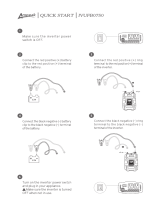
1. Place the inverter on a flat surface on your vehicle floor.
2. Make sure the power switch on the panel is off.
3. Take the power cord equipped with the cigar plug and place the ring
terminals over the two cabling terminals on the back of the inverter.
4. Place the inverter cigar plug in the vehicle cigarette lighter socket.
5. Turn on the power switch. The green light indicates that the inverter is
operating normally and that AC power is available at the outlet.
6. Verify that the connected device(s) draws less than 150 watts and plug
into the AC outlet.
7. Always turn the inverter off when not in use.
Follow these steps to connect the power inverter directly to the vehicle's
battery (for loads over 150 watts).
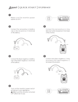
1. Place the inverter on a flat surface.
2. Make sure the power switch on the panel is off.
3. Take the power cord equipped with battery clamps on one end and
place the ring terminals over the two cabling terminals on the back of
the inverter.
4. Fasten the positive (red) clamp to the positive battery post, and then
fasten the negative (black) clamp to the negative battery post.
5. Turn on the power switch. The green light indicates that the inverter is
operating normally and that AC power is available at the outlet.
6. Take device power cord plug into the inverter AC outlet.
7. Always turn the inverter off when not in use.
Make sure you connect cable red to red and black to black, and make
sure you screw the nuts on tightly.
Use the cigar plug cable only when the vehicle’s engine is running.
Use the cigar plug cable with the engine off will cause excessive
battery drain.
• Do not operate the inverter near flammable materials, fumes, or
gases.
• Always use the inverter where there is adequate ventilation. Do not
obstruct the ventilation slots.
• Never immerse the unit in water or other liquids.
• Proper cooling is essential when operating the inverter. Refrain from
placing the inverter near the vehicle's heat vent or in direct sunlight.
• Always turn the inverter off by removing it from the DC accessory
socket when not in use.
• Check the warning labels on battery chargers or adapters before
connecting them to the inverter. Do not connect battery chargers or
adapters with warnings about using with inverters.
CAUTION :
1. Connect the RED cable to the
POSITIVE terminal of the battery.
2. Connect the BLACK cable to the
NEGATIVE terminal of the battery.
A reverse polarity connection (positive to negative) will blow a fuse in
the inverter and may permanently damage the unit. Damage caused
by a reverse polarity connection is not covered by your warranty.
Batteries contain corrosive materials and present an electrical shock
hazard. To prevent irritation and burns, wear protective eyewear and
clothing when you install the inverter or work with the batteries.Take
special care to ensure that metal tools and personal metal objects like
rings and bracelets do not contact the battery terminals.
CAUTION
WARNING
CAUTION
Battery
Red
Black
(+)
(-)
CAUTION :
1. Connect the RED cable to the
POSITIVE terminal of the inverter.
2. Connect the BLACK cable to the
NEGATIVE terminal of the inverter.
Front View
Back View
1
2
3
5
6
7
8
4
1 1
480 User Guide
AC Mobile Power Inverter
CPS480TG2U
Introduction
Product Overview
Product Features
Operation: Connecting the power cord for loads under
150 watts
Operating and Storage Tips
Operation: Connecting the power cord for loads over
150 watts
Package Contents
Operating Tips
The inverter should only be operated under the following conditions:
• Dry - Do not allow water or other liquids to come into contact with the
inverter.
• Moderate Temperature - Ambient air temperature should be between
32
o
F - 104
o
F (0
o
C - 40
o
C). Keep the inverter out of direct sunlight.
• Free Air Flow - Keep the inverter's ventilation slots unobstructed to
ensure air flow to the unit. Do not place any items on or over the inverter
during operation. The unit will shut down if it overheats.
Storage Tips
• Proper storage temperature range is 32
o
F - 122
o
F (0
o
C - 50
o
C)
• Store and use the inverter in a cool and dry environment.
• Avoid exposing the inverter to heating elements, direct sunlight, or high
humidity.

Spring
Decorative Ring
Contact Pin
Contact Retainer
15 ampFuse
12V DC Adapter
Problem
No AC output -
Red LED lit.
No AC output -
Green LED not
lit.
Motorized power
tool will not
operate
1.DC input is below 11
Vdc / Over 15Vdc
2.Short circuit.
3. Overload
4. Inverter hot.
1.Bad connection or
wiring
2.Fuse is blown
Excessive startup load.
If the start up load
exceeds the inverters
peak load capability it
will not work.
1.Check your battery volts
and recharge or replace the
battery.
2. Disconnect the load.
3. Reduce the load.
4. Disconnect the load and
operate the inverter for a
few minutes.
1.Tighten all DC connections.
2.Check fuse and replace or
Call Service
Disconnect the load until the
inverter operates normally
and connect the load again.
Suggested Solutions
Possible Cause
Figure 1. Fuse Replacement
K01-0000377-01
Note Page
Model
Input Voltage
Output Peak Power
Output Continuous Power
Output Voltage
Output USB Voltage
Output Frequency
Output Waveform
Input Fuse (Internal)
Input Fuse (Cigar plug)
Protection Features
CPS240PAU CPS480PAU
11 to 15 volts
240 Watts 480 Watts
200 Watts 400 Watts
120 Volts
5 Volts
60 Hz
Simulated Sine Wave
25Amp 25Amp x2
15Amp (CPS480PAU only)
Overload, Overvoltage,
Overheating, Short-circuit
DC Fuse Replacement (For Cigar Plug Cable)
Specifications
Troubleshooting
The CPS480PAU inverter contains a fuse inside in the cigar plug (see
Figure 1) to protect the unit against overloading. If the inverter draws
more than 150 watts, the internal fuse may open to protect the inverter,
vehicle battery, and the connected equipment. To replace the fuse, please
follow the instructions below:
1. Unplug the inverter from the power source.
2. Remove the contact retainer from the 12V DC adapter.
3. Replace the 15 amp fuse.
4. Reassemble the fuse, contact pin, and contact screw carefully.
5. Ensure all pieces shown in Figure 1 are installed in the correct
sequence.
CyberPower Systems (USA), Inc.
4241 12th Avenue East, Suite 400, Shakopee, MN 55379
TEL: (952) 403-9500 Toll-Free: (877) 297-6937
FAX: (952) 403-0009 E-mail: sales@cpsww.com
CPSww.com
C 2014 CyberPower Systems, Inc.
All rights reserved. Reproduction in whole or in part without permission is prohibited.
Limited Warranty
Product Registration
Technical Support
Legal notices (FCC Part 15)
CyberPower warrants this CPS240PAU / CPS480PAU (the "Inverter") to be free from
material and manufacturing defects for two years. If a defect results in product failure
during its normal use, CyberPower’s sole responsibility is to repair or replace (at its
sole option) the Inverter.
The foregoing Limited Warranty is the consumer’s sole and exclusive remedy and
excludes any incidental or consequential damages. Some States do not allow the
exclusion or limitation of incidental and consequential damages, so certain of the
above limitations or exclusions may not apply to you (the Consumer). This limited
warranty gives the Consumer specific legal rights and the Consumer may have other
rights, which vary from State to State.
To make a Limited Warranty claim:
1. Pack and ship the Inverter to CyberPower at 4241 12th Avenue East, Suite 400,
Shakopee, MN 55379.
2. Clearly indicate on the outside of the packaging that this is a “WARRANTY
RETURN”
3. Clearly include your name and address (a) on the outside packaging and (b) on a
sheet of paper enclosed in the box with the Inverter that is being returned.
4. You MUST prepay all shipping costs and you are responsible for packaging and
shipment.
CAUTION: Any changes or modifications not expressly approved by the guarantee
of this device could void the user’s authority to operate the equipment.
Thank you for purchasing a CyberPower product. Prompt product registration entitles
coverage under the Limited Warranty and also allows the opportunity to be notified of
product enhancements, upgrades, and other announcements.
Registration is quick and easy at www.cpsww.com/register
Feel free to contact our Tech Support department with installation, troubleshooting, or
general product questions.
CyberPower Technical Support
Phone: 1-877-297-6937
Email: [email protected]
Web: www.CPSww.com
Address: 4241 12th Ave. E., STE 400, Shakopee, MN 55379
Hours of Operation: Monday – Friday, 7:00am – 6:00pm (CST)
This equipment has been tested and found to comply with the limits for a Class B Digital Device,
pursuant to Part 15 of the FCC Rules. These limits are designed to provide reasonable protection
against harmful interference in residential installation. This equipment generates, uses and can
radiate radio frequency energy and, if not installed and used in accordance with the instructions,
may cause harmful interference to radio communications. However, there is no guarantee that
interference will not occur in a particular installation. If this equipment does cause harmful
interference to radio or television reception, which can be determined by turning the equipment off
and on, the user is encouraged to try to correct the interference by one or more of the following
measures: (1) Reorient or relocate the receiving antenna. (2) Increase the separation between the
equipment and receiver. (3) Connect the equipment into an outlet on a circuit different from that to
which the receiver is connected. (4) Consult the dealer or an experienced radio/TV technician for
help. Any special accessories needed for compliance must be specified in the instruction.
CAUTION: A shielded-type power cord is required in order to meet FCC emission limits and
also to prevent interference to the nearby radio and television reception. It is essential that only the
supplied power cord be used. Use only shielded cables to connect I/O devices to this equipment.
/


