Page is loading ...

• Spark resistant, cast aluminum airfoil axial impeller
• Aerodynamically efficient performance
• Factory set adjustable pitch blades
• Heavy duty welded steel construction
• TEFC industrial duty motor
• Mountable in ductwork in any position
• Sizes range from 12” to 60”
• Belt drive capacities to 54,000 cfm
IN-LINE FANS
AIB
BELT DRIVE
TUBEAXIALS

STANDARD FEATURES & BENEFITS
• Spark resistant, cast aluminum airfoil axial impeller
• Factory set adjustable pitch blades
• Aerodynamically efficient performance
• Heavy duty welded steel and angle ring construction
• Air dried enamel paint finish
• Mountable in ductwork in any position
• TEFC industrial duty motor
• Motor located outside of air stream
• Self-aligning pillow block ball bearings
• V-belt drives for low speed operation
• Completely sealed belt tube protects sheaves and belts from air stream
• Maximum 225 F operation
• Extended lube lines
• Shaft seal & water slinger
APPLICATIONS
• Process ventilation • Moisture laden air • Fumes, dust or smoke removal
• In-line duct booster • General ventilation • Contaminated air streams
ACCESSORIES / OPTIONS
• Epoxy or Eisenheiss coatings • Propeller side guard • 304 or 316 stainless steel construction
• Horizontal mounting brackets • Motor side guard • Maximum 375 F construction
• Vertical mounting brackets • Inspection door • Explosion proof & special duty motors
• Mounting legs • Companion flanges • Motor cover and/or belt guard
• Reverse flow construction • Variable pitch sheaves • AMCA spark resistant construction
MODEL A B C D
WT (LBS)
LESS MTR
MAX MTR
FRAME
AIB-12 12 13.1 14 18 50 143T
AIB-15 15 16.1 17 18 65 143T
AIB-18 18 19.1 20 18 80 145T
AIB-24 24 25.8 27 18 100 184T
AIB-27 27 28.8 30 18 115 184T
AIB-30 30 31.8 33 18 125 184T
AIB-34 34 35.8 37 18 150 184T
AIB-36 36 37.9 39 18 195 215T
AIB-42 42 43.6 45 22 280 215T
AIB-48 48 49.6 51 24 345 215T
AIB-54 54 55.6 57 28 430 215T
AIB-60 60 61.6 63 30 540 215T
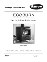
DIMENSIONS IN INCHES*
7/16” DIA. HOLES
PER FLANGE
D
VARIE S
WITH MOTOR
A
B
C
AIRFLOW
SHAFT SEAL
WATER SLINGER
PILLOW
BLOCK
BEARINGS
GREASE
FITTINGS
VARIE S
WITH
MOTOR
AIB BELT DRIVE TUBEAXIAL FANS
MODEL
MINIMUM
CFM
MAXIMUM
CFM
AIB-12 600 2,044
AIB-15 1,000 4,250
AIB-18 1,500 5,350
AIB-24 1,775 11,400
AIB-27 2,000 13,480
AIB-30 3,500 16,440
AIB-34 6,700 20,500
AIB-36 9,500 22,500
AIB-42 9,950 33,300
AIB-48 13,900 41,200
AIB-54 18,000 45,000
AIB-60 20,000 54,000
PERFORMANCE RATING
*DO NOT USE FOR CONSTRUCTION CONSULT FACTORY FOR CERTIFIED PRINTS
2

AIB BELT DRIVE TUBEAXIAL FANS
PRODUCT SPECIFICATION GUIDE
1.0 GENERAL
A. Fans shall be model AIB Belt Drive Tubeaxial Fans, as manufactured by Continental Fan Manufacturing Inc.,
of Buffalo, NY, and of the size and capacity as indicated on the drawings and fan schedule.
B. Fans shall be rated and tested in accordance with ANSI/AMCA Standard 210-99.
C. All motors and electrical components shall conform to NEMA standards.
2.0 FAN HOUSING
A. Fan housing shall be constructed of heavy gauge steel and welded angle ring flanges.
B. Fan motor base shall be adjustable, and be located on the exterior of the fan housing.
C. Fan belt tube shall be completely sealed, and shall isolate the bearings from ambient and/or contaminated airstreams.
D. Fan housing and motor base shall be coated with an air dried gray enamel finish.
3.0 FAN IMPELLER
A. Axial impeller shall be constructed of spark resistant, die cast aluminum airfoil shaped blades secured to a die
cast aluminum hub assembly.
B. Axial impeller blades shall be of adjustable pitch construction with multiple hub-to-blade arrangements to max-
imize air performance. Blade pitch angles shall be factory set.
C. Axial impeller hub shall be designed to incorporate a split taper bushing, and be keyed directly to motor shaft.
4.0 FAN MOTOR AND DRIVE
A. Motor shall be TEFC industrial duty and conform to NEMA standards.
B. Motor shall be of voltage, horsepower, RPM and enclosure as indicated on the fan schedule.
C. Fan sheaves shall be cast iron and appropriately sized and aligned.
D. Fan belts shall be static conducting, plus oil and heat resistant.
E. Fan shaft shall be steel, turned, ground and polished.
F. Fan shaft bearings shall be lubricated, self-aligning ball type in cast iron pillow block mounts with external
grease fittings.
5.0 OPTIONAL FAN ACCESSORIES
A. Where indicated, fan shall be provided with the following optional accessories:
• Guards • Protective coatings for fan housing
- Propeller side - Epoxy
- Motor side - Eisenheiss
• Mounting brackets • Motors
- Horizontal - Explosion proof
- Vertical - Special duty
• Mounting legs • 304 stainless steel construction
• Inspection door • 316 stainless steel construction
• Companion flanges • AMCA spark resistant construction
• Motor cover and/or belt guard • Variable pitch sheaves
6.0 FAN TESTING
A. Axial impeller shall be balanced and mounted in fan assembly.
B. Fan assembly shall be run and tested prior to shipment.
C. A test report shall be maintained on file for each individual fan.
3

AIB-1006
AIB BELT DRIVE TUBEAXIALS
/