Page is loading ...

Documentazione
Tecnica
47
rev. 3.3
12/2003
©
CAME
CANCELLI
AUTOMATICI
C 100 / C BY / C BYT
CANCELLI AUTOMATICI
ITALIANO/ENGLISH/ ESPAÑOL
119C47-1
SERIE C |
C SERIES
|
SERIE C
75
3
2
486 1 6
TX
TX
RX
RX
4x1
2x1
2x1
4x1
6x1,5
2x1,5
TRG58
3x1
3x1,5
230V
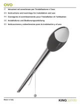
1. Gruppo C
2. Quadro comando
3. Ricevitore radio
4. Lampeggiatore di movimento
5. Antenna
6. Fotocellule di sicurezza
7. Selettore a chiave
8. Maniglia di sblocco
1. C unit
2. Control panel
3. Radio receiver
4. Flashing movement warrning light
5. Antenna
6. Safety photocells
7. Key-operated selector switch
8. Release handle
1. Grupo C
2. Cuadro de mando
3. Radioreceptor
4. Làmpara intermitente de movimiento
5. Antena
6. Fotocélula de seguridad
7. Selector con Ilave
8. Tirador de desbloqueo
Automazioni per applicazioni industriali
Automation systems for industrial applications
Automatización aplicaciones industriales
Impianto tipo -
Standard installation -
Instalaciòn tipo
Impianto tipo
Sandard installation
Instalacion tipo

-2-
ITALIANO • ENGLISH • ESPAÑOL
Caratteristiche generali
Attenzione! Controllate che le apparecchiature di comando, di sicurezza e gli accessori siano originali CAME; ciò
garantisce e rende l'impianto di facile esecuzione e manutenzione.
Accessori di completamento:
ZC3-ZC5-ZM2 quadro comando per C BY - C 100.
ZT4 quadro comando per C BYT.
CCT catena da 1/2".
CGIU giunto per catena.
C1-C2S per portoni sezionali.
C1P-C2P per portoni scorrevoli, a scomparsa ed a libro.
C1-C2F per finestre wasistas ed a sporgere.
C1-C2H per serrande.
CMS dispositivo di sblocco con maniglia e cordino comple-
to di chiavi personalizzate.
CGP guida per catena e carter di protezione per portoni
scorrevoli.
Descrizione:
- Motoriduttori idonei alla movimentazione di portoni sezio-
nali, a scomparsa, scorrevoli, a libro, finestre wasistas ed
a sporgere, serrande a scorrimento orizzontale o verticale
con palo rotante.
- Progettati e costruiti interamente dalla CAME Cancelli
Automatici S.p.A.,
- Grado di protezione IP 54.
- Garantiti 24 mesi salvo manomissioni.
Modelli:
C100 - Motoriduttore irreversibile 300W.
CBY - Motoriduttore irreversibile 450W.
CBYT - Motoriduttore irreversibile trifase 600W.
Modelos:
C100 - Motorreductor irreversible 300W.
CBY - Motorreductor irreversible 450W.
CBYT - Motorreductor irreversible trifase 600W.
Descripción:
- Motorreductores idóneos para mover puertas secciona-
les, ocultas, correderas, articulads, ventanas abatibles y
salientes, puertas enrollables con deslizamiento horizon-
tal o vertical con eje rotatorio.
- Diseñado y fabricado enteramente por CAME Cancelli
Automatici S.p.A.,
- Grado de protección IP54.
- Garantizado 24 meses, salvo manipulaciones.
Atención! Comprobar que los equipos de mando, de seguridad y los acesorios sean originales CAME; lo cual garantiza
y facilita el uso y el mantenimiento del aparato.
Características Generales
Accesorios que lo completan:
ZC3-ZC5-ZM2 cuadro de mando para C BY - C 100.
ZT4 cuadro de mando para C BYT.
CCT cadena de 1/2".
CGIU unión para cadena.
C1-C2S para puertas seccionales.
C1P-C2P para puertas correderas, ocultas y articulados.
C1-C2F para ventanas abatibles y salientes.
C1-C2H para puertas enrollables.
CMS dispositivo de desbloqueo con manilla y cuerda con
llaves personalizadas.
CGP guía para cadenay cubierta de proteccion para puer-
tas de corredera.
Description:
- Gearmotors designed to action sectional doors, folding
doors, sliding or hinged doors, wasistas and hinged win-
dows and vertical or horizontal rotating pole shutters.
- Designed and constructed entirely by CAME Cancelli
Automatici S.p.A.
- IP 54 protecting rating.
- Guaranteed for 24 months, unless tampered with by un-
authorized personnel.
Attention! to insure easy installation and conformance with current safety norms, we raccomend installation of CAME
safety and control accessories.
General specifications
Accessories for installation:
ZC3-ZC5-ZM2 control panel for C BY - C 100.
ZT4 control panel for C BYT.
CCT 1/2" chain.
CGIU coupling for chain.
C1-C2S for sectional doors.
C1P-C2P for sliding doors, folding doors, hinged doors.
C1-C2F for wasistas and hinged windows.
C1-C2H for shutters.
CMS release mechanism with handle and cable, complete
with keys.
CGP chain guide and protection casing of sliding gates.
Models:
C100 - 300W non-reversible gearmotor.
CBY - 450W non-reversible gearmotor.
CBYT - 600W three-phase non-reversible gearmotor.
ESPAÑOL
ITALIANO
ENGLISH

-3-
ITALIANO • ENGLISH • ESPAÑOL
210
250
280
k
y
180
133
87
x
353
160
180
C 100C BY/C BYT
205
x
= min. 147 max. 175
y
= min. 186 max. 213
k
= min. 333 max. 388
65
Dati relativi ai valori di alimentazione nomi-
nale.
*Regolabile mediante quadri comando
CAME.
N.B.: in nessun caso può essere affidata
all'irreversibilità del motoriduttore, la sicu-
rezza anticaduta nelle movimentazioni a
scorrimento verticale (es: sezionali).
These technical specifications apply when unit
is powered at nominal voltage.
*Adjustable using CAME control panels.
N.B.: when fitted to vertical-opening doors (e.g.
sectional doors), the non-reversibility of the
gearmotor must never be used as a safety
device to prevent accidental falling. A specific
safety device must be fitted.
Datos relativos a los valores de alimenta-
ción nominal.
*Regulable mediante cuadros de mando
CAME.
NOTA: durante los movimientos con desli-
zamiento vertical (ej: seccionales) no se
puede, en ningún caso, confiar en la irre-
versibilidad del motorreductor para la se-
guridad anticaída.
Caratteristiche tecniche -
Technical features
- Descripción técnica
Tipo Peso Alimentazione Corrente
nominale
Potenza Intermittenza
lavoro
Rapporto di
riduzione
Coppia Velocità di
rotazione
Condensatore
Type Weight Power supply Nominal
current
Power Duty cycle Reduction ratio Torque Speed of
rotation
Capacitor
Tipo Peso Alimentación Corriente
nominal
Potencia Intermit.
trabajo
Relación
de reduc.
Par Velocidad
de rotac.
Condensador
Kg V A W % i N.m rpm µF
C 100 8.5
230
2.3 300
30
1/32 26 * 42 20
C BY
18.5
4450
1/30
50 *
45
31.5
C BYT 230 - 400 2 - 1.2 600 50 50 -
Misure di ingombro -
External dimensions
- Dimensiones máximas
Controlli preliminari -
Preliminary checks
- Controlas preliminares
- Controllare che non vi sia attrito tra
parti fisse e mobili e la struttura del
serramento sia adeguatamente robu-
sta.
- Controllare che il percorso dei cavi
elettrici sia eseguito secondo le di-
sposizioni di comando e sicurezza
(vedi impianto tipo).
NOTA: le applicazioni che seguono
sono solo degli esempi in quanto lo
spazio per il fissaggio del motore e
degli accessori varia a seconda de-
gli ingombri e pertanto spetta all'in-
stallatore la soluzione più idonea.
- Check that there is no friction between
moving parts and fixed parts and that
the structure of the door is sufficiently
robust.
- Check that the path of the electrical
wiring is in compliance with the safety
and control instructions (see Standard
installation).
N.B.: the applications shown below are
examples. Since the space available for
installation of the motor and the acces-
sories varies, the installer should se-
lect the most suitable solution.
- Controbar que no haya roce entre
las partes fijas y móviles y la estruc-
tura del cerramiento sea adecuada-
mente robusta.
- Controbar que el recorrido de los
cables eléctricos esté realizado se-
gún las disposiciones de mando y
seguridad (véase instalation están-
dar).
NOTA: las aplicaciones siguientes
son sólo ejemplos, porque el espa-
cio para la fijación del motor y de
los accesorios varía según las di-
mensiones, por lo tanto es deber del
instalador encontrar la solución más
idónea.

-4-
ITALIANO • ENGLISH • ESPAÑOL
CBY/CBYT
CBY/CBYT
Portone sezionale -
Sectional door
- Puerta seccional
1) Portare l'anta a circa metà della
corsa.
2) Adattare il foro del pignone a 36
denti (accessorio C1-C2S) al Ø del
palo-molla e fissarlo con saldatura.
3) Fissare il motore col pignone del-
lo stesso allineato col pignone a 36
denti, sbloccarlo (tirare la staffa A) e
collegare la catena da 1/2" tra i due
pignoni, in modo tale che questa non
sia in tensione.
1) Move the door to approximately the
half-open position.
2) Adapt the hole of the 36-tooth pinion
(C1-C2S accessory) to suit the diame-
ter of the spring-roller and weld into po-
sition.
3) Fit the motor with its pinion, in align-
ment to the 36-tooth pinion. Release the
motor by pulling bracket "A" and con-
nect the 1/2" between the two pinion.
N.B. The chain should be slightly taut.
1) Colocar la hoja a la mitad de la
carrera.
2) Adaptar el agujero del piñón de
36 dientes (accesorio C1-C2S) al Ø
del eje-muelle y fijarlo soldándolo.
3) Fijar el motor con el piñón del
mismo alineandolo con el piñón de
36 dientes, desbloquearlo (tirar del
estribo A) y colocar la cadena de 1/
2" entre los dos piñones de manera
que no esté sometida a tensión.
Con questa applicazione si ottiene:
This application gives the following per-
formance:
Con esta aplicación se obtiene:
Pignone (36 denti)
Pinion (36 teeth)
Piñón (36 dientes)
Palo-molla
Spring-roller
Barra-muelle
Pignone motore
Motor pinion
Piñón motor
Catena da 1/2”
1/2” chain
Cadena da 1/2”
Staffa A
Bracket A
Estribo A
Anta
Door
Hoja
Tipo Coppia Giri del pignone Z=36
(con finecorsa di serie)
Velocità di rotazione
albero condotto
Ty p e To r qu e Pinion revolutions Z=36
(with standar limit stop)
Speed of rotation
of driven shaft
Typ Par Giros del piñón Z=36
(con final de carrera de serie)
Velocidad de rotación
árbol conducido
N·m n° rpm
C 100 62
14
17.5
C BY
120 18.5
C BYT

-5-
ITALIANO • ENGLISH • ESPAÑOL
Fig. A
Finestra wasistas -
Wasistas window
- Ventana abatibles
1) Portare l'anta/e a circa metà della
corsa, fissare il motore e sbloccarlo
(fig. A).
2) Inserire nell'albero di trasmissione
(da 1") il pignone a 15 denti
(accessorio C1-C2F), alineandolo col
pignone motore e fissarlo con
saldatura. Collegare la catena da 1/
2" tra i due pignoni in modo tale che
questa non sia in tensione.
1) Move the wing/s to approximately the
half-open position, fit the motor and
action the release mechanism (fig. A).
2) Fit the 15-tooth pinion (accessory C1-
C2F) to the drive shaft (the 1"), in align-
ment with the motor pinion, and weld
into position. Fit the 1/2" chain to the
two pinions. The chain should be slight-
ly taut.
1) Colocar la hoja/las hojas a la mi-
tad de la carrera, fijar el motor y des-
bloquearlo (fig. A).
2) Introducir en el árbol de transmi-
sión (de 1") el piñón de 15 dientes
(accesorio C1-C2F), alineandolo con
el piñón motor y fijarlo soldándolo.
Colocar la cadena de 1/2" entre los
dos piñones de manera que no esté
sometida a tensión.
This application gives the following per-
formance:
Con questa applicazione si ottiene: Con esta aplicación se obtiene:
Anta
Wing
Hoja
Albero di trasmissione
Drive shaft
Arbol de trasmission
Cremagliera
Rack
Cremallera
Catena da1/2”
1/2” chain
Cadena de 1/2”
Pignone (15 denti)
Pinion (15 teeth)
Piñón 815 dientes)
Pignone motore
Motor pinion
Piñón motor
Staffa di
fissaggio
Bracket
Estribo de
fijacion
Tipo Coppia Velocità di rotazione albero condotto
Ty pe Torque Speed of rotation of driven shaft
Typ Par Velocidad de rotaziòn à rbol conducido
N·m rpm
C 100 26 42
C BY
50 45
C BYT

-6-
ITALIANO • ENGLISH • ESPAÑOL
C BY/C BYT
1) Inserire all'estremità del palo della
serranda (Ø max. 60.4 mm), la corona
e fissarla con saldatura.
2) Fissare il motore col pignone dello
stesso allineato con la corona,
sbloccarlo (tirare la staffa A) e
collegare la catena da 1/2" tra corona
e pignone motore in modo tale che
questa non sia in tensione.
1) Fit the crown wheel to the extremity
of the rotating pole (max. Ø 60.4 mm)
and weld into position.
2) Fit the motor with its pinion in
alignment with the crown wheel. Release
the motor by pulling bracket "A" and
connect the 1/2" chain between the
crown wheel and the motor pinion. The
chain should be slightly taut.
1) Introducir en el extremo del eje de
la puerta enrollable (Ø máx. 60.4 mm)
la corona y fijarla soldándola.
2) Fijar el motor con el piñón del
mismo alineado con la corona,
desbloquearlo (tirar del estribo A) y
colocar la cadena de 1/2" entre
corona y piñón motor de manera que
no esté sometida a tensión.
Con questa applicazione si ottiene:
This application gives the following
performance:
Con esta aplicación se obtiene:
Corona (60 denti)
60-tooth crow wheel
Corona (60 dientes)
Pignone motore
Motor pinion
Piñón motor
Staffa A
Bracket A
Estribo A
Catena da 1/2”
1/2” chain
Cadena de 1/2”
Palo della
serranda
Rotating pole
Eje de la puerta
Type Coppia Giri della corona Z=60
(con finecorsa di serie)
Velocità di rotazione
albero condotto
Typ e Torque Crown wheel revolutions Z=60
(with standar limit stop)
Speed of rotation
of driven shaft
Typ Par Giros de la corona Z=60
(con final de carrera de serie)
Velocidad de rotación
árbol conducido
N·m n° rpm
C 100 100
8.5
10.5
C BY
200 11
C BYT
Serranda con palo rotante -
Rotating-pole shutters
- Puerta enrollable con eje rotatorio

-7-
ITALIANO • ENGLISH • ESPAÑOL
C BY/C BYT
B
CGP
Fig. 2Fig. 1
Portone scorrevole a due ante -
Two-wing sliding doors
- Puerta corredera a dos hojas
1) Portare le ante a circa metà della
corsa, fissare il motore e sbloccarlo
(tirare la staffa A).
2) Applicare l'accessorio C1P (per C
100), C2P (per C BY / C BYT) come
segue:
- fissare il rinvio tendicatena opposto
al motore ed in asse con il pignone
dello stesso;
- se presente, fissare la guida per
catena (CGP) tra motore e rinvio;
- applicare la catena (la lunghezza
della catena, deve essere 2 volte la
distanza B). Regolare la tensione
della stessa mediante la vite del
rinvio e bloccare i dadi. N.B.: la
catena non deve essere in tensione;
- fissare gli appositi attacchi (staffe e
piastre) prima alla catena e poi alle
ante e aplicare il carter di protezione
(CGP).
1) Move the wings to approximately the
half-open position and fit the motor.
Release the motor by pulling bracket
"A".
2) Fit accessory C1P (for C 100) or C2P
(for C BY / CBYT) as follows:
- fit the chain tensioner attachment on
the side opposite the motor, in alignment
with the motor pinion;
- position the chain guide (CGP, if
featured) between the motor and the
chain tensioner;
- fit the chain (the length of the chain
should be twice distance "B"). Adjust
the chain tension by turning the screw
on the tensioner, then tighten the nuts
securely. N.B.. the chain should be
slightly taut;
- fit the brackets and plates first to the
chain and then to the wings and fit the
protective cover (CGP).
1) Colocar las hojas a la mitad de la
carrera, colocar el motor y
desloquearlo (tirar del estribo A).
2) Aplicar el accesorio C1P (para
C100), C2P (para CBY / CBYT) de la
siguiente manera:
- fijar el renvío tensor de cadena
opuesto al motor y en eje con el
piñón del mismo;
- si está presente, fijar la guía para
cadena (CGP) entre el motor y el
renvío;
- aplicar la cadena (la longitud de la
cadena debe ser el doble de la
distancia B). Regular la tensión de la
misma mediante el tornillo del renvío
y bloquear las tuercas. Nota: la
cadena no debe estar sometida a
tensión;
- fijar los adecuados ancajes
(estribos y placas) primero a la
cadena y posteriormente a las hojas
y aplicar el cárter de protección
(CGP).
Attenzione: le sopraccitate istruzioni
valgono anche su portone scorrevole sia a
libro (fig.1) che ad un'anta (fig.2).
Important: the instructions shown above are
also applicable to book-type sliding doors (fig.1)
and sigle-wing (fig.2).
Atención!: las instrucciones amba
mencionadas se refieren también a puertas
correderas articuladas (fig.1) y a una hoja
(fig.2).
Dado
Nut
Tuerca
Vite
Bolt
Tornillo
Rinvio tendicatena
Chain tensioner
attachment
Renvio tensor de
cadena
Piastra
Plate
Placa
Catena da 1/2”
1/2” chain
Cadena de 1/2”
Staffa A
Bracket A
Estribo A
Pignone
motore
Motor pinion
Piñón motor
Luce netta
Net aperture
Luz neta
Staffa
Bracket
Estribo

-8-
ITALIANO • ENGLISH • ESPAÑOL
UVW056T78
FC FA
F
TEWVU
ZT4
* Per aperture maggiori (10.5 m),
sostituire il pignone del gruppo finecorsa
con un pignone a 15 denti (C100) o con
pignone da 21 denti (CBY/CBYT), oppure
applicare dei finecorsa ausiliari
sostituendoli a quelli in dotazione.
* For wider apertures (10.5 m), replace the
limit stop pinion with a 15-tooth pinion
(C100) or a 21-tooth pinion (CBY/CBYT).
Alternatively, fit auxiliary limit stops in place
of the standard limit stops.
* Para aperturas mayores (10.5 m),
sustituir el piñón del grupo final de
carrera con un piñón de 15 dientes
(C100) o con un piñón de 21 dientes
(CBY/CBYT), o bien aplicar finales de
carrera auxiliares que sustituyan los
suministrados.
Collegamenti elettrici -
Electrical connections
- Conexiones eléctricas
Installare il quadro comando e
procedere ai collegamenti elettrici
come indicato.
Install the electrical control panel and
connect the wiring as indicated.
Instalar el cuadro de mando y
proceder a las conexiones eléctricas
segùn lo indicado.
Quadro comando per CBYT |
control panel for CBYT
| Cuadro de mando para CBYT
Quadro comando
Control panel
Cuadro de mando
Morsettiera motore
Motor terminal block
Caja de bornes para el motor
U - V - W
Collegamento motore 1-2
Connection to motor 1-2
Conexión motor 1-2
Cortocircuitare
Short circuit
Cortocircuitar
0 - FC
Finecorsa chiude
Limit switch closure
Fin de carrera cierre
0 - FA
Finecorsa apre
Limit switch aperture
Fin de carrera apertura
Massa
Ground
Tierra
Con questa applicazione si ottiene:
This application gives the following
performance:
Con esta aplicación se obtiene:
Type Spinta Apertura *
(con finecorsa di serie)
Velocità di traslazione
Ty pe Thrust Aperture *
(with standar limit stop)
Speed of movement
Typ Empuje Apertura *
(con final de carrera de serie)
Velocidad de traslación
N·m m m/min
C 100 850 2 - 6 8
C BY
1500 0 - 6.5 8.5
C BYT

-10-
ITALIANO • ENGLISH • ESPAÑOL
C 100C BY - C BYT
Regolazioni dei microinterruttori -
Adjusting the microswitches
- Regulación de los microinterruptores
In apertura
Portare l'anta/e in posizio-
ne di apertura desiderata.
Ruotare una manopola
nera fino a far inserire il
microinterruttore.
Bloccare la relativa mano-
pola azzurra.
Aperture
Move the gate(s) to the
desired aperture position.
Turn one of the black knobs
until the microswitch is
tripped, then tighten the
corresponding light blue
knobs securely.
En fase de apertura
Llevar la/s hoja/s en la
posición de apertura
deseada. Girar una
manecilla negra hasta
introducir el micro-
interruptor. Bloquear la
correspon- diente
manecilla azul.
In chiusura
Portare l'anta/e in posi-
zione di chiusura. Ruo-
tare l'altra manopola
nera fino a far inserire
il microin terruttore.
Bloccare la relativa ma-
nopola azzurra.
Closure
Move the gate(s) to the
closed position. Turn the
second black knob until
the microswitch is tripped,
then tighten the corre-
sponding light blue knob
securely.
En fase de cierre
Colocar la/s hoja/s en la
posición de cierre. Girar
la otra manecilla negra
hasta introducir el micro-
interruptor. Bloquear la
correspondiente maneci-
lla azul.
In apertura
Portare l'anta/e in posizio-
ne di apertura desiderata.
Ruotare una vite fino a far
inserire il microinter-
ruttore nel nottolino di
scorrimento.
In chiusura
Portare l'anta/e in posi-
zione di chiusura. Ruo-
tare l'altra vite fino a far
inserire il microinter-
ruttore nel nottolino.
Aperture
Move the gate(s) to the ap-
erture position. Turn one of
the screws until the mi-
croswitch is inserted into
the sliding pawl.
Closure
Move the gate(s) to the
closed position. Turn the
second screw until the
microswitch is inserted
into the sliding pawl.
En fase de apertura
Llevar la/s hoja/s en la
posición de apertura de-
seada. Enroscar un torni-
llo hasta introducir el mi-
crointerruptor en el trin-
quete.
En fase de cierre
Colocar la/s hoja/s en
la posición de cierre.
Enroscar el otro torni-
llo hasta introducir el
microinterruptor en el
trinquete.
Manopole nere
Black Knobs
Manecillas negras
Nottolino
Pawl
Trinquete
Manopole blu
Light blu Knobs
Manecillas azules
Microinteruttori
Microswitches
Microinterruptores
Viti
Screws
Tornillos
Nottolino
Pawl
Trinquete

-11-
ITALIANO • ENGLISH • ESPAÑOL
CMS CGP
C 1P
C 2P
C1-C2H C1-C2S
CCT
CGIU
C1-C2F
60,4 mm
34 mm
Il gruppo non necessita di alcuna manu-
tenzione specifica. Solo come misura
cautelativa e in caso di servizio intensi-
vo è opportuno controllare la tensione
della catena e le parti di contatto tra
struttura fissa e mobile (es. guide e ca-
relli su portoni scorevoli e cerniere su
quelli a libro, etc.).
This unit requires no specific maintenance.
However, as a precaution and in case of
heavy-duty service, it is advisable to check
the chain tension and to check for friction
between fixed and moving parts (e.g.
guides and slides on sliding doors, hing-
es on book-type doors, etc.).
El conjunto no necesita ningún manteni-
miento específico. Sólo como medida
cautelar y en caso de uso intenso es
conveniente controlar la tensión de la
cadena y las partes de contacto entre
estructura fija y móvil (ej.: guías y ca-
rretes en las puertas correderas y bisa-
gras en las articuladas, etc.).
Manutenzioni periodiche -
Periodic maintenance
- Mantenimiento periódico
Carter (L= 1,5/2 m)
Casing (L= 1,5/2 m)
Carter (L= 1,5/2 m)
Guida per catena (L=1,5/2 m)
Chain guide (L=1,5/2 m)
Guia para cadena (L=1,5/2 m)
Piastra
Plate
Placa
Rinvio tendicatena
Chain tensioner
attachment
Renvio tensor de
cadena
Staffa
Bracket
Placca
Piastra
Plate
Placa
Rinvio tendicatena
Chain tensioner
attachment
Renvio tensor de
cadena
Corona (60 denti)
60 tooth crown whell
Corona (60 dientes)
Catena da 1/2” (130 passi)
1/2” chain (130 links)
Cadena de 1/2” (130 pasos)
Pignone (36 denti)
Pinion (36 teeth)
Piñón (36 dientes)
Catena da 1/2” (78 passi)
1/2” chain (78 links)
Cadena de 1/2” ( 78 Pasos)
Pignone (15 denti)
Pinion (15 teeth)
Piñón (15 dientes)
Catena da 1/2” ( 78 passi)
1/2” chain (78 links)
Cadena de 1/2” ( 78 pasos)
Catena da 1/2” ( L= 5 m)
1/2” chain ( L= 5 m)
Cadena de 1/2” ( L= 5 m)
Giunto
Coupling
Unión
Staffa -
Bracket
- Placca
Accessori -
Accessories
- Accesorios

CANCELLI AUTOMATICI
CAME LOMBARDIA S.R.L.______COLOGNO M. (MI)
(+39) 02 26708293 (+39) 02 25490288
CAME SUD S.R.L. ___________________NAPOLI
(+39) 081 7524455 (+39) 081 7529109
CAME (AMERICA) L.L.C.____________MIAMI ( FL)
(+1) 305 5938798 (+1) 305 5939823
CAME AUTOMATISMOS S.A__________MADRID
(+34) 091 5285009 (+34) 091 4685442
CAMEBELGIUM NU-SA_______________LESSINES
(+32) 068 333014 (+32) 068 338019
CAME FRANCE S.A.____NANTERRE CEDEX ( PARIS)
(+33) 01 46130505 (+33) 01 46130500
CAME GMBH________KORNTAL BEI (STUTTGART)
(+49) 07 15037830 (+49) 07 150378383
CAME GMBH____________SEEFELD BEI (BERLIN)
(+49) 03 33988390 (+49) 03 339885508
CAME PL SP.ZO.O______________WARSZAWA
(+48) 022 8365076 (+48) 022 8369920
CAME UNITED KINGDOM LTD___NOTTINGHAM
(+44) 01159 210430 (+44) 01159 210431
CAME CANCELLI AUTOMATICI S.P.A.
DOSSON DI CASIER (TREVISO)
(+39) 0422 4940 (+39) 0422 4941
SISTEMA QUALITÀ
CERTIFICATO
ASSISTENZA TECNICA
NUMERO VERDE
800 295830
W
EB
www.came.it
E-
MAIL
Tutti i dati sono stati controllati con la massima cura. Non ci assumiamo comunque
alcuna responsabilità per eventuali errori od omissioni.
All data checked with the maximum care. However, no liability is accepted for any
error or omission.
Todos los datos se han controlado con la máxima atención. No obstante no nos
responsabilizamos de los posibles errores u omisiones.
DICHIARAZIONE DEL FABBRICANTE
Ai sensi dell’Allegato II B della Direttiva Macchine 98/37/CE
I Rappresentanti della
CAME Cancelli Automatici S.p.A.
via Martiri della Libertà, 15
31030Dosson di Casier - Treviso - ITALYtel
(+39) 0422 4940 - fax (+39) 0422 4941
internet: www.came.it - e-mail: [email protected]
Dichiarano sotto la propria responsabilità che i/il prodotto/i denominato/i ...
… sono conformi alle disposizioni legislative Nazionali che traspongono le seguenti Direttive
Comunitarie (dove specificatamente applicabili):
DIRETTIVA MACCHINE 98/37/CE
DIRETTIVA BASSA TENSIONE 73/23/CEE - 93/68/CEE
DIRETTIVA COMPATIBILITÀ ELETTROMAGNETICA 89/336/CEE - 92/31/CEE
DIRETTIVA R&TTE 1999/5/CE
Inoltre, dichiara che il/i prodotto/i, oggetto della presente dichiarazione, sono costruiti nel rispetto
delle seguenti principali norme armonizzate:
EN 292 PA RT E 1ª E 2ª SICUREZZA DEL MACCHINARIO.
EN 12453 CHIUSURE INDUSTRIALI, COMMERCIALI …
EN 12445 CHIUSURE INDUSTRIALI, COMMERCIALI …
EN 60335 - 1 SICUREZZA NEGLI APPARECCHI AD USO DOMESTICO ...
EN 60204 - 1 SICUREZZA DEL MACCHINARIO.
EN 50081 - 1 E 2COMPATIBILITÀ ELETTROMAGNETICA.
EN 50082 - 1 E 2COMPATIBILITÀ ELETTROMAGNETICA.
AVVERTENZA IMPORTANTE!
È vietato mettere in servizio il/i prodotto/i, oggetto della presente dichiarazione, prima del
completamento e/o incorporamento, in totale conformità alle disposizioni della Direttiva
Macchine 98/37/CE
Firma dei Rappresentanti
Documentazioni tecniche specifiche dei prodotti sono disponibili a richiesta!
Data della presente dichiarazione 07/12/2001
Also, they furthermore represent and warrant that the product/s that are the subject of the present
Declaration are manufactured in the respect of the following main harmonized provisions:
EN 292 PART 1 AND 2MACHINERY SAFETY.
EN 12453 INDUSTRIAL, COMMERCIAL AND OTHER CLOSING MECHANISMS.
EN 12445 INDUSTRIAL, COMMERCIAL AND OTHER CLOSING MECHANISMS.
EN 60335 - 1 SAFETY IN APPARATUSES FOR HOME USE.
EN 60204 - 1 MACHINERY SAFETY.
EN 50081 - 1 AND 2ELECTROMAGNETIC COMPATIBILITY.
EN 50082 - 1 AND 2ELECTROMAGNETIC COMPATIBILITY.
IMPORTANT CAUTION!
It is forbidden to market/use product/s that are the subject of this declaration before completing and/
or incorporating them in total compliance with the provisions of Machinery Directive 98/37/CE
Signatures of the Representatives
Specific technical documentation on the products is available on request!
Date of the present declaration 07/12/2001
MANUFACTURER’S DECLARATION
As per Enclosure II B of Machinery Directive 98/37/CE
The representatives of
CAME Cancelli Automatici S.p.A.
via Martiri della Libertà, 15
31030 Dosson di Casier - Treviso - ITALY
tel (+39) 0422 4940 - fax (+39) 0422 4941
internet: www.came.it - e-mail: [email protected]
Hereby declare, under their own respons ibility, that the product/s called ...
… comply with the Italian National Legal Provisions that transpose the
following Community Directives (where specifically applicable):
MACHINERY DIRECTIVE 98/37/CE
LOW VOLTAGE DIRECTIVE 73/23/EEC - 93/68/EEC
LECTROMAGNETIC COMPATIBILITY DIRECTIVE 89/336/EEC - 92/31/EEC
R&TTE DIRECTIVE 1999/5/CE
DECLARACION DEL FABRICANTE
De conformidad con el Anexo II B de la Directiva de Máquinas 98/37/CE
Fecha de la presente declaración 07/12/2001Adjunta a la documentación técnica (el original de la Declaración está disponible previa petición)
Los Representantes de la compañía
CAME Cancelli Automatici S.p.A.
via Martiri della Libertà, 15
31030 Dosson di Casier - Treviso - ITALY
tel (+39) 0422 4940 - fax (+39) 0422 4941
internet: www.came.it - e-mail: [email protected]
Declaran bajo su responsabilidad que el/los producto/s denominado/s ...
… cumplen con las disposiciones legislativas nacionales que trasponen las siguientes
Directivas Comunitarias (donde específicamente aplicables):
DIRECTIVA DE MÁQUINAS 98/37/CE
DIRECTIVA DE BAJA TENSIÓN 73/23/CEE - 93/68/CEE
DIRECTIVA DE COMPATIBILIDAD ELECTROMAGNÉTICA 89/336/CEE - 92/31/CEE
DIRECTIVA R&TTE 1999/5/CE
Los productos objeto de esta declaración están fabricados respetando las siguientes normas
armonizadas:
EN 292 PA RTE 1ª Y 2ª SEGURIDAD DE LAS MÁQUINAS.
EN 12453 CIERRES INDUSTRIALES, COMERCIALES …
EN 12445 CIERRES INDUSTRIALES, COMERCIALES …
EN 60335 - 1 SEGURIDAD DE LOS APARATOS PARA USO DOMÉSTICO...
EN 60204 - 1 SEGURIDAD DE LAS MÁQUINAS.
EN 50081 - 1 E 2COMPATIBILIDAD ELECTROMAGNÉTICA.
EN 50082 - 1 E 2COMPATIBILIDAD ELECTROMAGNÉTICA.
AVVERTENZA IMPORTANTE!
Está prohibido hacer uso de el/los producto/s, objeto de la presente declaración antes de completarlo/
s y/o incorporarlo/s en total conformidad a las disposiciones de la Directiva de Máquinas 98/37/CE.
Firma de los Representantes
Documentación técnica específica de los productos está disponible previa petición
Enclosed with the technical documentation (the original copy of the Declaration is available on request)
Allegata alla documentazione tecnica (l’originale della Dichiarazione è disponibile a richiesta)
RESPONSABILE TECNICO
Sig. Gianni Michielan
PRESIDENTE
Sig. Paolo Menuzzo
TECHNICAL MANAGER
Mr. Gianni Michielan
MANAGING DIRECTOR
Mr. Paolo Menuzzo
RESPONSABLE TÉCNICO
Sr. Gianni Michielan
PRESIDENTE
Sr. Paolo Menuzzo
C100 • C-BY • C-BYT
C1-P • C1-C2F • C1-C2H • C1-C2S • C2-P
CCT • CGIU • CGP • CMS
C100 • C-BY • C-BYT
C1-P • C1-C2F • C1-C2H • C1-C2S • C2-P
CCT • CGIU • CGP • CMS
C100 • C-BY • C-BYT
C1-P • C1-C2F • C1-C2H • C1-C2S • C2-P
CCT • CGIU • CGP • CMS

CANCELLI AUTOMATICI
CAME LOMBARDIA S.R.L.______COLOGNO M. (MI)
(+39) 02 26708293 (+39) 02 25490288
CAME SUD S.R.L. ___________________NAPOLI
(+39) 081 7524455 (+39) 081 7529109
CAME (AMERICA) L.L.C.____________MIAMI ( FL)
(+1) 305 5938798 (+1) 305 5939823
CAME AUTOMATISMOS S.A__________MADRID
(+34) 091 5285009 (+34) 091 4685442
CAMEBELGIUM NU-SA_______________LESSINES
(+32) 068 333014 (+32) 068 338019
CAME FRANCE S.A.____NANTERRE CEDEX ( PARIS)
(+33) 01 46130505 (+33) 01 46130500
CAME GMBH________KORNTAL BEI (STUTTGART)
(+49) 07 15037830 (+49) 07 150378383
CAME GMBH____________SEEFELD BEI (BERLIN)
(+49) 03 33988390 (+49) 03 339885508
CAME PL SP.ZO.O______________WARSZAWA
(+48) 022 8365076 (+48) 022 8369920
CAME UNITED KINGDOM LTD___NOTTINGHAM
(+44) 01159 210430 (+44) 01159 210431
CAME CANCELLI AUTOMATICI S.P.A.
DOSSON DI CASIER (TREVISO)
(+39) 0422 4940 (+39) 0422 4941
SISTEMA QUALITÀ
CERTIFICATO
ASSISTENZA TECNICA
NUMERO VERDE
800 295830
W
EB
www.came.it
E-
MAIL
Toutes les données ont été contrôlées très soigneusement. Nous n’assumons de
toute façon aucune responsabilité pour les erreurs ou omissions éventuelles.
Die Daten wurden mit höchster Sorgfalt geprüft. Für eventuelle Fehler oder
Auslassungen übernehmen wir keine Haftung.
De gegevens in deze handleiding werden zorgvulding gecontroleerd.
Wij zijn niet verantwoordelijk oor eventuele drukfouten.
Annexe à la documentation technique (l’original de la Déclaration est disponible sur demande)
DECLARATION DU FABRICANT
Aux termes de l’Annexe II B de la Directive Machines 98/37/CE
Date de la présente déclaration 07/12/2001
Les Représentants de la
CAME Cancelli Automatici S.p.A.
via Martiri della Libertà, 15
31030 Dosson di Casier - Treviso - ITALY
tel (+39) 0422 4940 - fax (+39) 0422 4941
internet: www.came.it - e-mail: [email protected]
déclarent sous leur propre responsabilité que le/les produit/s appelé/s ...
… sont conformes aux Dispositions législatives nationales qui transposent les Directives
communautaires suivantes (où elles sont applicables de façon spécifique):
DIRECTIVE MACHINES 98/37/CE
DIRECTIVE BASSE TENSION 73/23/CEE - 93/68/CEE
DIRECTIVE COMPATIBILITÉ ELECTROMAGNÉTIQUE 89/336/CEE - 92/31/CEE
DIRECTIVE R&TTE 1999/5/CE
Ils déclarent également que le/s produit/s, objet de la présente déclaration, sont fabriqués
conformément aux principales normes harmonisées suivantes:
EN 292 PARTIE 1 ET 2SÉCURITÉ DES MACHINES.
EN 12453 FERMETURES DANS LE SECTEUR INDUSTRIEL, COMMERCIAL …
EN 12445 FERMETURES DANS LE SECTEUR INDUSTRIEL, COMMERCIAL …
EN 60335 - 1 SÉCURITÉ EN CE QUI CONCERNE LES APPAREILS À USAGE DOMESTIQUE ...
EN 60204 - 1 SÉCURITÉ DES MACHINES.
EN 50081 - 1 E 2COMPATIBILITÉ ÉLECTROMAGNÉTIQUE.
EN 50082 - 1 E 2COMPATIBILITÉ ÉLECTROMAGNÉTIQUE.
AVIS IMPORTANT!
Il est interdit de mettre le/s produit/s, objet de la présente déclaration, en service avant de les
incorporer à l’installation et/ou de terminer le montage de cette dernière, conformément aux dispositions
de la Directive Machines 98/37/CE
Signature des Représentants
PRESIDENT
Monsieur Paolo Menuzzo
La documentation technique spécifique des produits est disponible sur demande!
VERKLARING VAN DE FABRIKANT
volgens bijlage II B van de Machinerichtlijn 98/37/EG
Bijlage technische documentatie (op aanvraag kan het origineel van de verklaring verkregen worden)
Datum van de verklaring 07/12/2001
De vertegenwoordigers van
CAME Cancelli Automatici S.p.A.
via Martiri della Libertà, 15
31030 Dosson di Casier - Treviso - ITALY
tel (+39) 0422 4940 - fax (+39) 0422 4941
internet: www.came.it - e-mail: [email protected]
verklaren onder eigen verantwoordelijkheid dat het product / de producten met naam...
… conform zijn aan de nationale wettelijke beschikkingen die de volgende Communautaire
Richtlijnen weerspiegelen (waar specifiek van toepassing):
MACHINERICHTLIJN 98/37/EG
LAAGSPANNINGSRICHTLIJN 73/23/EEG - 93/68/EEG
RICHTLIJN ELEKTROMAGNETISCHE COMPATIBILITEIT 89/336/EEG - 92/31/EEG
RICHTLIJN R&TTE 1999/5/EG
Verklaren bovendien dat het product / de producten waarop deze verklaring van toepassing is gebouwd
werden volgens de volgende belangrijkste geharmoniseerde normen:
EN 292 1° EN 2° DEEL VEILIGHEID VAN MACHINES.
EN 12453 INDUSTRIËLE, COMMERCIËLE AFSLUITEN …
EN 12445 INDUSTRIËLE, COMMERCIËLE AFSLUITEN …
EN 60335 - 1 VEILIGHEID VOOR HUISHOUDELIJKE APPARATUUR ...
EN 60204 - 1 VEILIGHEID VAN MACHINES.
EN 50081 - 1 EN 2ELEKTROMAGNETISCHE COMPATIBILITEIT.
EN 50082 - 1 EN 2ELEKTROMAGNETISCHE COMPATIBILITEIT.
BELANGRIJKE INFORMATIE!
Het is verboden het product / de producten waarop deze verklaring betrekking heeft in werking te
stellen alvorens deze vervolledigd en/of ingebouwd werden volgens de beschikkingen van de
Machinerichtlijn 98/37/EG.
Handtekening van de vertegenwoordigers
TECHNISCHE VERANTWOORDELIJKE
De heer Gianni Michielan
De specifieke technische documentatie van de producten is op aanvraag beschikbaar!
ERKLÄRUNG DES HERSTELLERS
gemäß Anlage II B der Maschinen-Richtlinie 98/37
Anlage zur technischen Dokumentation (das Original der Erklärung ist auf Anforderung verfügbar)
Datum der vorliegenden Erklärung 07/12/2001
Die Vertreter der
CAME Cancelli Automatici S.p.A.
via Martiri della Libertà, 15
31030 Dosson di Casier - Treviso - ITALY
tel (+39) 0422 4940 - fax (+39) 0422 4941
internet: www.came.it - e-mail: [email protected]
erklären unter ihrer eigenen Verantwortung, daß das/die genannte/n Produkt/e
…mit den nationalen gesetzlichen und den nachstehenden EG-Richtlinien (im Fall ihrer spezifischen
Anwendbarkeit) entsprechenden Verordnungen übereinstimmen:
EG-Maschinenrichtlinie 98/37
EG-Richtlinie über Niedrigspannung 73/23-93/68
EG-Richtlinie über elektromagnetische Kompatibilität 89/336 – 92/31
EG-Richtlinie R & TTE 1999/5
Es wird ferner erklärt, daß das/die Produkt/e, Gegenstand der vorliegenden Erklärung, unter
Beachtung der folgenden angepaßten Hauptvorschriften hergestellt wurden:
EN 292 Teil 1 und 2
Maschinensicherheit
EN 12453 Industrie-, Geschäfts…..Schließvorrichtungen
EN 12445 Industrie-, Geschäfts….Schließvorrichtungen
EN 60335-1 Sicherheit der Geräte für den Hausgebrauch
EN 60204-1 Maschinensicherheit
EN 50081-1 U. 2 elektromagnetische Kompatibilität
EN 50082-1 U.2 elektromagnetische Kompatibilität
WICHTIGE HINWEISE !
Es ist verboten das/die Produkt/e, Gegenstand der vorliegenden Erklärung, vor seiner/ihrer
Vervollständigung u/o Eingliederung, in vollkommener Übereinstimmung mit den Verordnungen der
EG-Maschinenrichtlinie 98/37, in Betrieb zu nehmen.
Unterschrift der Vertreter
TECHNISCHER LEITER
Herr Gianni Michielan
Spezifische technische Unterlagen der Produkte sind auf Anforderung lieferbar.
RESPONSABLE TECHNIQUE
Monsieur Gianni Michielan
VOORZITTER
De heer Paolo Menuzzo
PRÄSIDENT
Herr Paolo Menuzzo
C100 • C-BY • C-BYT
C1-P • C1-C2F • C1-C2H • C1-C2S • C2-P
CCT • CGIU • CGP • CMS
C100 • C-BY • C-BYT
C1-P • C1-C2F • C1-C2H • C1-C2S • C2-P
CCT • CGIU • CGP • CMS
C100 • C-BY • C-BYT
C1-P • C1-C2F • C1-C2H • C1-C2S • C2-P
CCT • CGIU • CGP • CMS

-2-
CARACTÉRISTIQUES GÉNÉRALES
ATTENTION: avant d'intervenir à l'intérieur de
l'appareillage, couper la tension de ligne
DESCRIPTION
The ZC4 command board is suitable for
controlling 230V monophase automation
devices with up to 600W power and is
particularly suitable for C and F3000 series
reduction gears for industrial gates (sliding,
swing, sectional, etc.)
It should be installed inside S4339 or S4340
cases, which include air recycling inlet and
transformer (see last page).
The board requires 230V (a.c.) on terminal
blocks L1 and L2, and is protected with two 5A
fuses, whilst the low voltage command devices
are protected by a 3,15A fuse.
The accessorie's total capacity (24V) should not
exceed 20W.
Fixed operating time of 80 seconds.
SAFETY
Photocells can be connected to abtain:
-
Re-opening during closure (2-C1), if the
photocells identify an obstacle while the gate is
closing, they will reverse the direction of
movement until the gate is completely open;
- Total stop (1-2), shutdown of gate movement
without automatic closing, a pushbutton or radio
remote control must be actuated to resume
movement.
OPTIONAL ACCESSORIES
- 24V Electric lock (11-ES);
OTHER FUNCTIONS
- Automatic closing. The automatic closing timer
is automatically activated at the end of the
opening cycle. The preset, adjustable automatic
closing time is automatically interrupted by the
activation of any safety system, and is
deactivated after a STOP command or in case
of power failure;
-
"Operator present". Gate operates only when
the pushbutton is held down (the radio remote
control system is deactivated);
ADJIUSTMENTS
- Automatic closure time;
IMPORTANT: Shut off the mains power
before servicing the inside of the unit.
GENERAL CHARACTERISTICS
DESCRIPTION
La carte ZC4 sert à commander les
automations à 230V monophasées avec
puissance jusqu’à 600W, en particulier les
motoréducteurs série C et F3000 pour
grandes portes d’usine (coulissantes,
pliantes, sectionnelles etc.).
Elle doit être montée à l’intérieur des boîtiers
S4339 ou S4340, qui sont équipés d’une
prise pour le recyclage de l’air et du
transformateur correspondant (voir dernière
page).
La carte doit être alimentée à 230V (c.a.) aux
bornes L1 et L2, et est protégée à l’entrée par
deux fusibles de 5A, tandis que les
dispositifs de commande à basse tension
(24V) sont protégés par un fusible de 3,15A.
La puissance totale des accessoires (24V) ne
doit pas dépasser 20W.
Temps de fonctionnement fixe de 80 sec.
SÉCURITÉ
Il est possible de brancher des photocellules
et de les programmer pour:
- Réouverture en phase de fermeture (2-C1),
les cellules photoélectriques provoquent
l'inversion de marche jusqu'à l'ouverture
complète si elles relèvent un obstacle durant
la phase de fermeture du portail;
-
Stop total (1-2), arrêt du portail et
désactivation d’un éventuel cycle de
fermeture automatique; pour activer de
nouveau le mouvement, il faut agir sur les
boutons-poussoirs ou sur la radiocom-
mande.
ACCESSOIRES POUVANT ÊTRE BRANCHÉS
- Serrure électrique 24V (11-ES);
AUTRES FONCTIONS
- Fermeture automatique. Le temporisateur
de fermeture automatique est autoalimenté à
la fin du temps de la course en ouverture. Le
temps réglable est programmé, cependant, il
est subordonné à l’intervention d’éventuels
accessoires de sécurité et il est exclu après
une intervention de “stop” ou en cas de
coupure de courant;
- Fonction “homme mort”. Fonctionnement
du portail en maintenant appuyé le bouton-
poussoir (exclut la fonction de la
radiocommande);
Réglages
- Temps de fermeture automatique;
FGB

-4-
1
2 3 4
L2T
L1T
02412
FUS . CENTRALI N A
T.C.A.
1 2
ZC4
QUADRO
COMANDO
FUSI BILI LIN EA
L1T L2T CT 0 24
12
PROG
SCHEDA BASE -
MOTHERBOARD
- CARTE BASE -
GRUNDPLATINE
- TARJETA BASE
COMPONENTI PRINCIPALI
1 Morsettiere di collegamento
2 Fusibili di linea 5A
3 Fusibile accessori 3,15A
4 Pulsante memorizzazione codice radio
5 Trimmer di regolazione tempo di chiusura automatica
6 Selettore funzioni a 2 dip (vedi pag. 14)
7 Innesto scheda radiofrequenza (vedi tabella)
8 LED segnalazione
9 Fori per fissaggio scheda
ITALIANO
1
2
3
4
5
6
7
8
9
Nota: collegare i fili neri
che fuoriescono dalla
scheda sui connettori
del condensatore.
NB: connect the black
wires coming out of the
board to the condenser’s
connectors.
Note: connecter les fils
noirs qui sortent de la
carte sur les
connecteurs du
condensateur.
Hinweis: Die schwarzen
Kabel, die von der Karte
wegführen, an die
Verbinder am
Kondensator
anschließen.
Nota: conectar los hilos
negros que salen de la
tarjeta en los
conectores del
condensador.

-5-
HAUPTKOMPONENTEN
1 AnschlußKlemmenleiste
2 Hauptsicherung 5A
3 Zubehör-Sicherung 3,15A
4 Knöpfe zum Abspeicher der Radiocodes
5 Trimmer zur Einstellung Schließautomatik
6 Wählschalter für Funktionen mit 2 Dip (sehen S. 14)
7 Steckanschluß Funkfrequenze-Platine AF (sehen Tabelle)
8 LED Kontrolleuchte zur Anzeige
9 Lochung für die Befestigung der Karte
PRINCIPALES COMPONENTES
1 Caja de bornes para las conexiónes
2 Fusibles de línea 5A
3 Fusible accesorios 3,15A
4 Teclas de memorización del código radio
5 Trimmer de regulación tiempo cierre automático
6 Selector de funciones con 2 dip (vedas pag. 14)
7 Conexión tarjeta radiofrecuencia AF (vedas tabla)
8 LED de señal
9 Perforaciones para fijación de la tarjeta
MAIN COMPONENTES
1 Terminal block for external conections
2 Line fuses, 5A
3 Fuse on accessory power line, 3,15A
4 Radio-code save buttons
5 Trimmer for adjustment automatic closing
6 2-dip function switch (see pag. 14)
7 Socket AF radiofrequency board (see table)
8 Signal LED
9 Grooves for board positioning
PRINCIPAUX COMPOSANTS
1 Plaque à bornes de connexion
2 Fusibles de ligne 5A
3 Fusible accessoires 3,15A
4 Boutons-poussoir mémorisation code radio
5 Trimmer de réglage fermeture automatique
6 Selecteur de fonctions à 2 interrupteurs à positions multiples (voir pag. 14)
7 Branchement carte radiofréquence AF (voir tableau)
8 LED de signalisation
9 Fentes pour fixer la carte
ENGLISH
FRANÇAIS
DEUTSCH
ESPANOL

-6-
1111
1111
11
ESES
ESES
ES
W
E1
U
W
V
L1
L2
10
11
Alimentazione 230V (a.c.)
230V (a.c.) power input
Alimentation 230V (c.a.)
Stromversorgung 230V (Wechselstrom)
Alimentación 230V (a.c.)
Motore monofase 230V (a.c.)
230V (a.c.) single-phase motor
Moteur monophasé 230V (c.a.)
Einphasenmotor 230V (Wechselstrom)
Motor monofásico 230V (a.c.)
Uscita 230V (a.c.) in movimento
(es.lampeggiatore - max. 25W)
230V (a.c.) output in motion
(e.g. flashing light - max. 25W)
Sortie 230V (c.a.) en mouvement
(ex. branchement clignotant - max. 25W)
Ausgang 230V (Wechselstrom) in Bewegung
(z.B. Blinker-Anschluß - max. 25W)
Salida de 230V (a.c.) en movimento
(p.ej. conexión lámpara intermitente - max. 25W)
Collegamento elettroserratura (12V-15W max.)
(12V-15W max.) connection for electrically-actuated lock
Connexion serrure électrique (12V-15W max.)
Anschluß Elektroschloß (12V-15W max.)
Conexión electrocerradura (12V-15W max.)
Alimentazione accessori 24V (a.c.) max. 20W
24V (a.c.)Powering accessories (max 20W)
Alimentation accessoires 24V (c.a.) max. 20W
Zubehörspeisung 24V (Wechselstrom) max. 20W
Alimentación accesoios 24V (a.c.) max. 20W
Lampada spia (24V-3W max.) "cancello aperto"
(24V-3W max.) "gate-opened" signal lamp
Lampe-témoin (24V-3W max.) "portail ouverture"
Signallampe (24V-3W max.) "Tor Öffnen"
Lámpara indicadora (24V-3W max.) "puerta abierta"
11
FC
COLLEGAMENTI ELETTRICI -
ELECTRICAL CONNECTIONS -
BRANCHEMENTS ÉLECTRIQUES
ELEKRISCHE ANSCHLÜSSE -
CONEXIONES ELÉCTRICAS
L1 L2 U V W E1 10 11 1 2 7 FC1 FAFC
10 11 1 2 7 C1 FA FC FES

-7-
11
FA
2
7
Lampada spia (24V-3W max.) "cancello chiuso"
(24V-3W max.) "gate-closed" signal lamp
Lampe-témoin (24V-3W max.) "portail fermeture"
Signallampe (24V-3W max.) "Tor Schließen"
Lámpara indicadora (24V-3W max.) "puerta cierre"
Pulsante stop (N.C.)
Pushbutton stop (N.C.)
Bouton-poussoir arrêt (N.F.)
Stop-Taste (N.C.)
Pulsador de stop (N.C.)
Contatto radio e/o pulsante per comando
Contact radio and/or button for control
Contact radio et/ou poussoir pour commande
Funkkontakt und/oder Taste Steuerart
Contacto radio y/o pulsador para mando
Contatto (N.C.) di «riapertura durante la chiusura»
Contact (N.C.) for «re-opening during the closing»
Contact (N.F.) de «réouverture pendant la fermeture»
Kontakt (Ruhekontakt) «Wiederöffnen beim Schliessen»
Contacto (N.C.) para la «apertura en la fase de cierre»
Collegamento (N.C.) finecorsa apre
Connection (N.C.) limit switch opens
Connexion (N.F.) fin de course ouverture
Anschluß (N.C.) Endschallter Öffnung
Conexión (N.C.) fin de carrera apertura
Collegamento (N.C.) finecorsa chiude
Connection (N.C.) limit switch closes
Connexion (N.F.) fin de course fermeture
Anschluß (N.C.) Endschallter Schließung
Conexión (N.C.) fin de carrera cierre
Collegamento antenna
Antenna connection
Connexion antenne
Antennenanschluß
Conexión antena
2
C1
F
FA
1
2
F
FC

-8-
A
max
300W
COLLEGAMENTO PER 2 MOTORI ABBINATI -
CONNECTIONS FOR 2 COMBINED MOTORS
CONNEXIONS POUR 2 MOTEURS ACCOUPLÉS
ANSCHLUSSE FÜR 2 PARALLELGESCHALTETEN MOTOREN
- CONEXIÓN PARA 2 MOTORES ACOPLADOS
In case two combined motors are installed,
proceed in the following manner:
- Coordinate the direction of the "A" and
"B" gearmotors, modifying the rotation of
motor "B";
- The same settings and functions must be
made on both control panels (fig. 1).
- Make the necessary electric connections
between the terminal boards of the "A"
and "B" (fig. 2);
N.B. In case of a paired connection, THE
COUPLING OF THE RADIO FREQUENCY
BOARD IS NOT PROVIDED FOR, so the
use of the wireless control is excluded in
this instance.
ENGLISH
Pour installer deux moteurs accouplés,
procéder comme suit:
- Coordonner le sens de marche des
motoréducteurs "A" et "B" en modifiant
la rotation du moteur "B";
- Les mêmes réglages et fonctions
doivent être effectués sur les deux
tableaux (fig. 1).
- Effectuer les branchements électriques
entre les plaques à borne du tableau "A"
et "B" (fig. 2);
N.B. En cas de branchement accouplé,
LA CARTE RADIOFRÉQUENCE N'EST
PAS PRÉVUE et l'utilisation de la
radiocommande est donc exclue.
FRANÇAIS
Wenn zwei kombinierte Motoren installiert
werden sollen, gehen Sie dazu bitte
folgendermaßen vor:
- Stimmen Sie die Laufrichtung der
Getriebemotoren "A" und "B" aufeinander
ab. Andern Sie dazu die Drehrichtung vom
Motor "B";
- An beiden Schalttafeln müssen die
gleichen Einstellungen erfolgen. Auch die
Funktionen müssen gleich sein (fig. 1);
-Führen Sie die elektrischen Anschlüsse
zwischen den Klemmbretter von Schalttafel
"A" und "B" so durch, wie auf (fig. 2)
Hinweis. Bei kombiniertem Anschluß IST
KEIN EINSTECKEN DER RADIO-
FREQUENZKARTE VORGESEHEN, d.h.
daß die Verwendung von Fernbedienungen
ausgeschlossen ist.
DEUTSCH
Nel caso d'installazione di due motori
abbinati, procedere nel seguente modo:
- Coordinare il senso di marcia dei
motoriduttori "A" e "B", modificando la
rotazione del motore "B";
- Su entrambi i quadri devono essere
fatte le stesse regolazioni e funzioni (fig.
1);
- Eseguire i collegamenti elettrici tra le
morsettiere del quadro "A" e "B" (fig. 2);
N.B. Nel caso di collegamento abbinato,
NON È PREVISTO L'INNESTO DELLA
SCHEDA RADIOFREQUENZA, di conse-
guenza viene escluso l'utilizzo del
radiocomando.
ITALIANO
B
max
300W

-10-
LIMITATORE DI COPPIA MOTORE /
MOTOR TORQUE LIMITER
/ LIMITEUR DE COUPLE MOTEUR
DREHMOMENTBEGRENZER DES MOTORS
/ LIMITADOR DE PAR MOTOR
1
234
L2T
L1T
02412
L1TL2T CT 0 2412
Per variare la coppia motrice, spostare il faston
indicato (con filo di colore nero) su una delle 4 posizioni;
1 min. - 4 max
To vary the motor torque, move the indicated faston
to one of the four positions: 1 min. - 4 max
Pour varier le couple du moteur, déplacer le
connecteur indiqué sur l'une des 4 positions; 1 min. - 4 max
Zur Änderung des Motor-Drehmoments den
angegebenen Faston auf eine der 4 Stellungen
positionieren: 1 min. - 4 max
Para variar el par motor, desplazar el faston indicado
hasta una de las 4 posiciones: 1 min. - 4 max
I
GB
F
D
E
SELEZIONI & REGOLAZIONI -
SELECTIONS & ADJUSTMENTS -
SÉLECTIONS & RÉGLAGES
FUNKTIONSWAHL & EINSTELLUNGEN -
SELECCIÓNES & REGULACIONES
T.C .A.
1 2
S
M
ON
OFF
REGULACIÓN TRIMMERS
EI NTE LL U NG TRIM MERS
RÉGLAGE TRIMMERS
TRIMMERS ADJUSTMENT
REGOLAZIONE TRIMMERS
T.C.A.
1 2
1 OFF "Operator present" disabled: radio
remote control is deactivated when
function is selected; (1 ON - enabled)
2 ON Automatic closing enabled;
(2 OFF - disabled)
Trimmer T.C.A.
= Adjusts automatic closing time
from a minimum of 3 seconds to a maximum of 120
seconds.
GB
1 OFF Bedienung vom "Steuerpul" deaktiviert:
bei Wahl dieser Betriebsart wird die
Funkfernsteuerung ausgesch.;
(1 ON - aktiviert)
2 ON Schließautomatik aktiviert;
(2 OFF - deaktiviert)
Trimmer T.C.A.
= Timer, auf dem die
Verzögerung für das automatische Schlißen mit
mindestens 3 Sekunden und höchstens 120
Sekunden eingestellt werden kann.
D
1 OFF "Hombre presente" desactivado:
escluye la función del mando de radio;
(1 ON - activado)
2 ON Cierre automático activado;
(2 OFF - desactivado)
Trimmer T.C.A.
= Réglage du temps de fermeture
automatique d'un minimum de 3 secondes à un
maximun de 120 secondes.
E
1 OFF "Homme mort" désactivèe: exclut la
fonction radiocommande;
(1 ON activée)
2 ON Fermeture automatique activée;
(2 OFF - désactiée)
Trimmer T.C.A.
= Réglage du temps de fermeture
automatique d'un minimum de 3 secondes à un
maximun de 120 secondes.
F
1 OFF "Uomo presente" disattivato: esclude
il funzionamento del radiocomando;
(1 ON - attivato)
2 ON Chiusura automatica attivata;
(2 OFF - disattivata)
Trimmer T.C.A.
= Regolazione tempo di chiusura
automatica da un minimo di 3 secondi a un mas-
simo di 120 secondi.
I

-11-
Assemblare le cerniere a pressione
Assemble the hinges by pressure
Assembler les charnières à pression
Setzen Sie die Druckscharniere
zusammen.
Ensamblar las bisagras a presión
Inserire le cerniere nella scatola (sul
lato destro o sinistro a scelta) e
fermarle con le viti e le rondelle in
dotazione
Insert the hinges (on the right or left
side, according to choice) and secure
using the screws and washers
supplied
Placer les charnières (du côté droit ou
gauche au choix) et les fixer avec les
vis et les rondelles fournies de série
Setzen Sie die Scharniere ein (je nach
Wunsch auf der rechten oder linken
Seite) und befestigen Sie sie mit den
mitgelieferten Schrauben und
Unterlegscheiben
Introducir las bisagras (en el lado
izquierdo o derecho, a placer) y fijarlas
con los tornillos y las arandelas
suministradas a tal efecto
2
1
!!
Posizionare e fissare la scatola del
quadro
Position and secure the control
panel housing
Placer et fixer la boîte de l'armoire
Plazieren Sie das Gehäuse der
Schalttafel und befestigen Sie
es.
Colocar y sujetar la caja del
cuadro
3
Inserire a scatto il coperchio sulle cerniere,
chiuderlo e fissarlo con le viti in dotazione
Snap the cover onto the hinges and secure
using the screws supplied.
Assembler par encliquetage le couvercle sur
les charnières et fixer le couvercle avec les vis
fournies de série
Lassen Sie den Deckel in den Scharnieren
einrasten und befestigen Sie ihn mit den
mitgelieferten Schrauben.
Introducir la tapa en las bisagras hasta oír un
chasquido y fijar la tapa con los tornillos
suministrados a tal efecto.
4
ISTRUZIONI MONTAGGIO -
ASSEMBLY INSTRUCTIONS -
INSTRUCTIONS MONTAGE
MONTAGEANWEISUNGEN -
INSTRUCCIONES MONTAJE
15 mm~
scorrono per ruotare
they must slide in order to turn
elles glissent pour tourner
laufen zum Drehen
deslizan para girar
215 mm
295 mm
/