Page is loading ...

Schwanenhals - Achtung
Zur Vermeidung von Überdehnungen und frühzeitigem Verschleiß
darf der Schwanenhals nur bis max. 90 Grad
gebogen werden.
Gooseneck - Caution
In order to avoid overstretching and premature wear and tear never
bend the gooseneck more than 90°.
Col de Cygne - Attention
Flexion de 90 degrés max. afin d’éviter tout sur-allongement et toute
usure prématurée.

3
BEDIENUNGSANLEITUNG MCS 50
OPERATING INSTRUCTIONS MCS 50
english deutsch
Kurzbeschreibung. . . . . . . . . . . . . . . . . . . . . . . Seite 4
MCS 50 Diskussions-Steuereinheit . . . . . . . . . . Seite 8
Installation MCS 50 und Sprechstellen . . . . . . . Seite 9
Inbetriebnahme . . . . . . . . . . . . . . . . . . . . . . . . Seite 10
MCS-Systemkonfiguration
über MCS-Editor . . . . . . . . . . . . . . . . . . . . . . . Seite 15
Glossar . . . . . . . . . . . . . . . . . . . . . . . . . . . . . . . Seite 18
Fehlercheckliste . . . . . . . . . . . . . . . . . . . . . . . . Seite 19
Ausführungen . . . . . . . . . . . . . . . . . . . . . . . . . Seite 20
Zubehör - optional . . . . . . . . . . . . . . . . . . . . . . Seite 20
Technische Daten . . . . . . . . . . . . . . . . . . . . . . . Seite 20
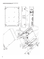
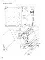
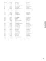
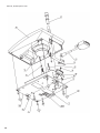
Explosionszeichnung / Ersatzteilliste
MCS 50 . . . . . . . . . . . . . . . . . . . . . . . . . . . . . . Seite 26
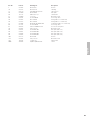
Explosionszeichnung / Ersatzteilliste
Sprechstellen MCS 521, 523 . . . . . . . . . . . . . . Seite 28
Konformitätserklärung . . . . . . . . . . . . . . . . . . . Seite 82
Short description . . . . . . . . . . . . . . . . . . . . . . . Page 30
MCS 50 Discussion control unit . . . . . . . . . . . . Page 34
Installation of MCS 50 and
Microphone units . . . . . . . . . . . . . . . . . . . . . . . Page 35
Setting up . . . . . . . . . . . . . . . . . . . . . . . . . . . . Page 36
MCS System Configuration via MCS-Editor . . . Page 41
Glossary . . . . . . . . . . . . . . . . . . . . . . . . . . . . . . Page 44
Trouble Shooting . . . . . . . . . . . . . . . . . . . . . . . Page 45
Versions . . . . . . . . . . . . . . . . . . . . . . . . . . . . . . Page 46
Optional Accessories . . . . . . . . . . . . . . . . . . . . Page 46
Technical Specifications. . . . . . . . . . . . . . . . . . . Page 46
Exploded View / Spare Parts MCS 50 . . . . . . . . Page 52
Exploded View / Spare Parts
MCS 521, 523 Microphone Units . . . . . . . . . . . Page 54
EC-Declaration of Conformity. . . . . . . . . . . . . . Page 82
NOTICE D’UTILISATION MCS 50
français
Description abrégée . . . . . . . . . . . . . . . . . . . . . Page 56
Centrale de contrôle MCS 50 . . . . . . . . . . . . . . Page 60
Installation de la centrale MCS 50 et
des postes . . . . . . . . . . . . . . . . . . . . . . . . . . . . Page 61
Opération. . . . . . . . . . . . . . . . . . . . . . . . . . . . . Page 62
Configuration du système MCS à l’aide
de l’Editeur MCS . . . . . . . . . . . . . . . . . . . . . . . Page 67
Glossaire . . . . . . . . . . . . . . . . . . . . . . . . . . . . . Page 70
Dépannage. . . . . . . . . . . . . . . . . . . . . . . . . . . . Page 71
Modèles . . . . . . . . . . . . . . . . . . . . . . . . . . . . . . Page 72
Accessories en option. . . . . . . . . . . . . . . . . . . . Page 72
Spécifications techniques . . . . . . . . . . . . . . . . . Page 72
Exploded View / Spare Parts MCS 50 . . . . . . . . Page 78
Exploded View / Spare Parts
MCS 521, 523 Microphone Units . . . . . . . . . . . Page 80
EC-Déclaration de Conformité . . . . . . . . . . . . . Page 82
INHALT / CONTENTS / SOMMAIRE
Page is loading ...
Page is loading ...
Page is loading ...
Page is loading ...
Page is loading ...
Page is loading ...
Page is loading ...
Page is loading ...
Page is loading ...
Page is loading ...
Page is loading ...
Page is loading ...
Page is loading ...
Page is loading ...
Page is loading ...
Page is loading ...
Page is loading ...
Page is loading ...
Page is loading ...
Page is loading ...
Page is loading ...
Page is loading ...
Page is loading ...
Page is loading ...
Page is loading ...
Page is loading ...

30
1. Short Description
1.1 MCS 50
The MCS 50 is a self-contained discussion control unit with integrated power supply and processor control for 32 or 64 microphone units. It is a
stand alone unit with multi-function buttons and LC-Display in a desktop housing that is suitable for 19" rack mounting. With this system the
500-series microphone units can be operated. The discussion control unit is delivered with a manufacturer specific configuration. The user, however,
can carry out a configuration of the system by himself. The configuration is controlled by using the multi-function buttons and the LC-Display. For an
extensive configuration, a PC can be connected to the service port and the supplied MCS-Editor software must be used. All functions of the
discussion control unit can be configured using this software. The system operates in a bus mode.
Safety Information
• Never expose the unit to water or excessive humidity. Do not install near swimming pools, spas, in a wet basement or in other excessively
humid environments.
• Never pour any liquids into the unit.
• Do not install or use this unit near sources of high heat, such as radiators, heat registers, flood lamps, spotlights, stoves, or other appliances.
• Always route cables running to the unit where they will not be pinched or cut by heavy or sharp objects.
• Always turn off the power to the amplifier when making input or output connections.
• Verify that the voltage rating of the unit matches that of the AC mains outlet you are to use. If you connect the unit to the wrong voltage,
you may seriously damage it.
• Do not put wires or small objects through any of the ventilation grilles. Electric shock may result.
• This unit needs a sufficient ventilation. Therefore, never cover the ventilation grilles. If you install the unit into a rack leave a minimum distance
of 1 U above and below the unit.
• Never place burning objects onto the unit.
1.2 Microphone Units
For the MCS 50 discussion control unit there are various chairman and delegate microphone units available:
MCS 521 and MCS 523 with loudspeaker.; MCS 501 and MCS 503 for installation into tables.
All microphone units (delegates and chairman) are equipped as follows.
• A connecting cable (3 m long) with a 15-pin Sub-D plug.
• A 15-pin Sub-D socket.
• A mini Mono jack for the connection of recorders, dictating machines etc. (except MCS 501 and MCS 503)
• A cardioid gooseneck microphone.
• A Dual colour LED that illuminates green when the microphone unit is switched on. When the system is operating in the Request-to-Talk mode,
the LED is illuminated red to indicate the registration as a Request-to-Talk. When the microphone is ready, the colour changes to green.
• An illuminated ring to indicate the Ready-to-Talk condition of the microphone unit, when the microphone is switched on.
• On the bottom of the microphone units there are DIP-switches for programming the microphone units (the DIP-switch no. 6 has no function).
Microphone Units with Loudspeakers (MCS 521 and MCS 523)
• Same as above with built-in wide-range loudspeaker.
• On the bottom of the unit there is an individual output volume control for the loudspeaker adjustable from 0 dB to -20 dB this is in addition to
the system level which is controlled via the MCS 50 (installation circumstances may demand lower loudspeaker levels to avoid feedback).
1.2.1 MCS 523 Chairman Microphone Unit
The chairman microphone unit is equipped with 3 buttons.
Priority button
The function of the priority button depends on how it has been configured in the MCS 50 discussion control unit. The chairman can either mute or
clear all activated delegate microphone units.
Microphone button
The microphone button allows the chairman to switch on his microphone unit independingly from the number of open microphones at any time.
Clear button
Pressing the clear button, the chairman clears all activated microphone units. In the Request-to-Talk mode all registered microphone units are also
cleared.
1.2.2 MCS 521 Delegate Microphone Unit
The delegate microphone unit is equipped with one button, the microphone button. Using this button, the delegates can switch their microphone
unit on and off or register in the Request-to-Talk mode.

31
english
1.2.3 MCS 503 and MCS 501 Microphone Units for Table Mounting
To install the MCS 501 (delegate version) or MCS 503 (chairman version) microphone unit into a table, you need an appropriate piece cut out of the
table. Please refer to the appropriate template.
Then mount the microphone unit with the supplied fittings.
The MCS 501 delegate microphone unit has a microphone button to switch the microphone unit on and off or to register the microphone unit in
the system with the “Request-to-Speak” operating mode.
The MCS 503 chairman microphone unit has a microphone button, priority and clear button. For function please refer to “1.2.1 Chairman
Microphone MCS 513, MCS 523”.
1.2.4 MCS 553 L and MCS 563 L System Unit for Mounting under the Table
The MCS 553 L and MCS 563 L system units have been developed for mounting under the table. Depending on the number of the connected
buttons the system units work as chairman unit (3 buttons: microphone, priority, clear) or delegate unit (1 button: microphone). Using the
MCS Editor software, the system unit is configured as chairman or delegate. Please refer also to chapter “6. MCS System Configuration via
MCS Editor”.
Mounting
There are holes needed in the table for the microphone and the buttons. Each system unit is mounted with 4 screws under the table. Please refer to
the appropriate template.
Connection
The system units are fitted with a fixed connecting cable and a connecting socket. The connection is according to the single cable principle, i.e. the
1st system unit is connected to the control unit, the 2nd system unit to the 1st system unit and so on.
The MCS 553 L is fitted with a detachable gooseneck microphone and a terminal board for the connection of buttons and a loudspeaker.
The MCS 563 L is fitted with a terminal board for the connection of microphone, LED ring, buttons and loudspeaker.

32
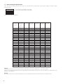
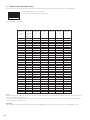
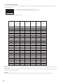
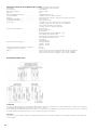
1.3 Addressing the Microphone Units
Before the system is set up, the microphone units have to be addressed via DIP-switches on the bottom according to the following table.
1 = DIP-switch in ON position = switched on
0 = DIP-switch in a number position = switched off
The DIP-switch 6 has no function.
Note:
At the factory the microphone unit 1 has been configured as a chairman microphone unit. Using the MCS-Editor another microphone unit can be
chosen as a chairman microphone unit.
Furthermore, make sure that there are not two microphone units having the same address within the same line. For assistance use the MCS-Editor
(refer to chapter 6.8 “Status Check”).
Important:
The chairman microphone unit has to be defined again with the MCS-Editor, when there is a reset necessary (user or manufacturer specific).
123456
ON
DIP-switch
1
0
1
0
1
0
1
0
1
0
1
0
1
0
1
0
1
0
1
0
1
0
1
0
1
0
1
0
1
0
1
0
1
DIP-switch
2
0
0
1
1
0
0
1
1
0
0
1
1
0
0
1
1
0
0
1
1
0
0
1
1
0
0
1
1
0
0
1
1
DIP-switch
3
0
0
0
0
1
1
1
1
0
0
0
0
1
1
1
1
0
0
0
0
1
1
1
1
0
0
0
0
1
1
1
1
DIP-switch
4
0
0
0
0
0
0
0
0
1
1
1
1
1
1
1
1
0
0
0
0
0
0
0
0
1
1
1
1
1
1
1
1
DIP-switch
5
0
0
0
0
0
0
0
0
0
0
0
0
0
0
0
0
1
1
1
1
1
1
1
1
1
1
1
1
1
1
1
1
Microphones
33 - 64
Line 2
(only MCS 50/64)
33
34
35
36
37
38
39
40
41
42
43
44
45
46
47
48
49
50
51
52
53
54
55
56
57
58
59
60
61
62
63
64
Microphones
1 - 32
Line 1
1
2
3
4
5
6
7
8
9
10
11
12
13
14
15
16
17
18
19
20
21
22
23
24
25
26
27
28
29
30
31
32

33
english
1.4 Maintenance of the MCS Microphone Units
For cleaning the MCS microphone units when they are slightly dirty (finger prints, dust, jam or juice) use a soft, damp cloth, sponge or brush and a
liquid cleaning agent. Before cleaning the surface it must be moistened thoroughly. Afterwards it must be cleaned with clear water. Make sure not to
allow any water to enter the unit. For dirt caused by mineral oils and fats, animal and vegetable fats use spirit, isopropyl alcohol or benzine.
For dirt caused by ballpoint pens, typewriter ribbons or carbon paper use isopropyl alcohol or spirit.
Clean the supplied pop shield with clear water. Make sure that it is completely dry before you put it on the microphone again.

34
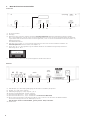
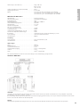
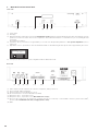
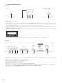
2. MCS 50 Discussion Control Unit
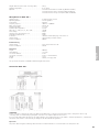
Front view
(1) Power switch
(2) LC-Display
(3) Master-Reset-button. If this button is pressed, the manufacturer specific parameters (average adjustments) are loaded. They guarantee a system
operation even if the user carries out an incorrect adjustment. As the Master-Reset-button is countersunk use a pen or something like that
for pressing.
Two multi-function buttons:
(4) Left button “Reset” pressed alone for approximately 12 seconds resets all adjustable parameters to user specific adjustments (refer to
chapter 5.3).
(5) Right button “N.o.m.” pressed alone shows the maximum number of switchable delegate microphone units for approximately 10 seconds.
(6) Serviceport, RS 232 interface for system configuration with the MCS-Editor via PC
Rear view
(7) Audio output: 3-pin XLR output for the connection of amplifiers, mixing consoles etc.
(8) Input, 3-pin XLR, balanced (250 mV)
(9) Extension input, 3-pin XLR, unbalanced (1,55 V)
(10) Record: Connection to record documentations (250 mV)
(11) Microphones Line 1, 15-pin Sub-D socket
(12) Microphones Line 2, 15-pin Sub-D socket (MCS 50/64 version only!)
(13) RS 232 for the connection of an operator’s PC (operation via mouse or touchscreen) or other available conference systems such as AMX
®
,
Crestron
®
. Use a standard RS 232 cable, straight, (female - male).
(14) Mains
Reset N.o.m.
Configuration
Max NOM 2
(1) (2) (3)(4) (6)(5)
(8)
(7) (9) (10) (11) (12) (13) (14)

35
english
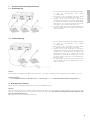
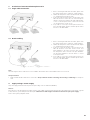
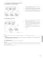
3. Installation of MCS 50 and Microphone Units
3.1 Single Cable Connection
1. Before connecting the MCS 50 to the mains, please check
the supply voltage (refer to chapter 4. “Supply Voltage”).
2. Address the microphone units as described in the chapter
1.3 “Addressing the microphone units”.
3. Connect the first microphone unit to the line input of the
MCS 50 discussion control unit. The other microphone
units are connected according to the single cable principle,
i.e. the second microphone unit is connected to the first
one, the third to the second one etc.
4. It is possible to connect up to 32 microphone units in one
line to the MCS 50/32 and up to 64 microphone units in
two lines to the MCS 50/64.
3.2 Branch Cabling
1. Before connecting the MCS 50 to the mains, please check
the supply voltage (refer to chapter 4. “Supply Voltage”).
2. Address the microphone units as described in the chapter
1.3 “Addressing the microphone units”.
3. Connect a 15-pin Sub-D cable to the line input of the
MCS 50 discussion control unit. Connect a CA 1513
triple distributor to the other end of the cable. Connect
two microphone units to the CA 1513 triple distributor.
The last triple distributor in the line allows to connect
3 microphone units.
4. It is possible to connect up to 32 microphone units in one
line to the MCS 50/32 and up to 64 microphone units in
two lines to the MCS 50/64.
Note:
The total length of the bus cable must not exceed 300 m. Each branch cable in this installation must not exceed 5 m.
Safety instructions
• Make sure that the MCS 50 discussion control unit is always switched off when connecting, disconnecting or addressing the microphone
units.
4. Supply Voltage / Power Supply
The power supply unit has been developed for an input voltage of 85 V to 264 V AC (50/60 Hz).
Caution:
If the F101 fuse of the integrated power supply (refer also to No. 200 in “Exploded View and Spare Parts, MCS 50 Discussion Control Unit”, page 48
to 49) is defective, you should replace the whole part. A different fuse with a higher value than 6.3 A can destroy the power supply.
Please contact your beyerdynamic-dealer.

36
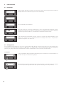
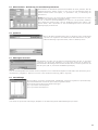
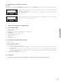
5. Setting up
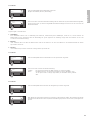
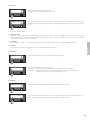
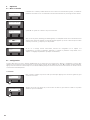
5.1 Switching on
When the system is switched on it carries out a system check checking all stored parameters. An error
message appears at a deviation.
System O.K. = the conference system is ready for operation
After the system check the default screen appears indicating the adjusted mode (Autonomy, Override,
Request-to-talk, Automatic), the signal level of the connected devices/microphone units and the actual
number of switched on microphones, including chairman microphone units.
If this error message occurs, carry out a configuration (refer to chapter 5.2 “Configuration” or adjust the user
specific parameters and configurate the corresponding parameters (refer to chapter “5.3 Adjusting the user
specific parameters”).
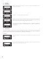
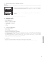
5.2 Configuration
You access the configuration menu when you press both buttons simultaneously of the switched on MCS 50. The arrows in the display indicate
which buttons of the device have to be pressed, left (Reset) = M, right (N.o.m.) = L. To exit the individual menu items press both buttons simultaneously.
You will access the main menu again or return to the operation mode. The entered data is stored automatically.
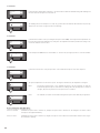
1. Parameter
In this menu the number of connected microphones can be adjusted. Press the left button (4) to enter the
sub-menu.
Press the left button (4) or right button (5) to enter the number. It is possible to enter 32 microphone units at
maximum. (As an option up to 64 microphone units.)
Reset N.o.m.
beyerdynamic
MCS 50 V.1 - Software Version (E)
Reset N.o.m.
System check please wait
Reset N.o.m.
System O.K.
Reset N.o.m.
Level
Override NOM 0
Reset N.o.m.
Wrong number of
microphone units
Reset N.o.m.
Number of mics
More
Reset N.o.m.
20
-+

37
english
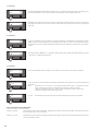
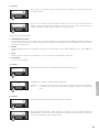
2. Parameter
In this menu the operation mode is adjusted.
Possibilities are: Autonomy, Override, Request-to-Talk
The current adjustment is shown in the top line. The operation mode is chosen with the left button (4), using
the right button (5) the chosen operation mode is confirmed and appears in the top line as present operation
mode.
There are three operation modes:
1. Request-to-Talk
This mode is only possible with an operator manually controlling a PC, media control system (AMX/Panja
®
, Crestron
®
). When pressing the
microphone button of the microphone unit the system registers a request-to-talk. The operator at the PC, console or touchscreen of the media
control system has control over who speaks next.
2. Autonomy
Each participant can switch on or off his microphone unit until the maximum number of open microphones (NOM) is reached.
3. Override
Each switched on microphone unit switches off the previously activated microphone unit.
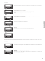
3. Parameter
In this menu the button function is adjusted in the microphone units.
The current adjustment is shown in the top line.
Switching: The microphone unit is switched on and off with the microphone button.
Push-To-Talk: The microphone button acts as a Push-To-Talk button (PTT) i.e. the microphone unit
is switched on as long as the microphone button is pressed.
4. Parameter
In this menu the talk time allowed of the delegate microphone unit is adjusted.
After the talk time allowed has elapsed (in this example 120 seconds) the delegate microphone unit
switches off automatically. Use the left (4) or right (5) button to adjust the value.
Reset N.o.m.
Operation mode
More
Reset N.o.m.
Autonomy
Override OK
Reset N.o.m.
Button mode
More
Reset N.o.m.
ON/OFF
PTT
Reset N.o.m.
Speech time
More
Reset N.o.m.
-+
120 sec.

38
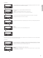
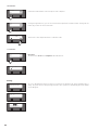
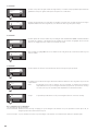
5. Parameter
In this menu the warning time is adjusted i.e. the time between which the illuminated ring starts flashing and
the time when the microphone is switched off.
The warning time (in this example 6 seconds) only operates when the talk time allowed has been previously
adjusted. Use the left (4) or right (5) button for adjusting.
6. Parameter
In this menu the number of the open delegate microphone units (NOM) can be adjusted. This adjustment can
be checked by pressing the right button (5) at any time. The adjustment should be performed according to the
acoustical conditions of the location.
In the example the NOM has been entered with “2”. Use the left (4) or right (5) button to enter the number.
7. Parameter
In this menu the function of the priority button of the chairman microphone unit can be adjusted.
The present adjustment is shown in the top line. Pressing the left button (4) the adjustment is changed.
Mute: Pressing the priority button of the chairman microphone unit the chairman can mute all
activated delegate microphone units while he is talking. When the priority button is switched
off again, all previously switched on microphones are re-activated.
Clear: The chairman can switch off all activated delegate microphone units with the priority button.
Note Configuration with MCS-Editor
(refer also to page 38 “Chairman mode”):
Function “Normal”: Chairman microphone unit is switched on, delegate microphone unit is switched off. The delegates can switch on their
microphone unit again immediately.
Function “Clear”: Chairman microphone unit is switched on, delegate microphone unit is switched off and remains switched off as long as
the chairman is speaking.
Reset N.o.m.
Warning time
More
Reset N.o.m.
-+
6 sec.
Reset N.o.m.
NOM
More
Reset N.o.m.
-+
2
Reset N.o.m.
Prior button
More
Reset N.o.m.
Mute
Clear
Reset N.o.m.
Clear
Mute

39
english
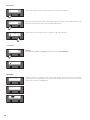
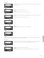
8. Parameter
In this menu the parameters of input levels can be adjusted. Press the left button (4) to enter the sub-menu.
Press the right button (5) to choose between:
- Microphone Line 1
- Microphone Line 2 (only with an extension for further 32 microphone units)
- Input
Pressing the left button (4) you will access the chosen menu item.
The present adjustment is shown in the top line. In this example the microphone line 1 is switched on.
Press the right button (5) to adjust the level.
Use the left (4) or right button (5) to adjust the level.
Important:
The microphone line 2 is only connected when using the MCS 50/64 version.
When the two buttons are pressed simultaneously the adjusted value is saved and you will return to the main menu. If you want to carry out more
level adjustments follow the steps as described in the 8. Parameter.
9. Parameter
In this menu the overall volume of the loudspeakers in the microphone units can be adjusted. The
adjustment is done when all input levels have been matched to each other with the same volume.
The adjustment of the output level is done in 2 dB-steps.
Important:
The output level of the Audio Output (7) and Record (10) for external devices (e.g. external sound
reinforcement system) is not affected.
Reset N.o.m.
Mic line 1
More
Reset N.o.m.
On
Off Level
Reset N.o.m.
-6 dB
-+
Reset N.o.m.
Mic line 2
More
Reset N.o.m.
Off
On
Reset N.o.m.
Input level
More
Reset N.o.m.
-4 dB
-+
Reset N.o.m.
Output level
More

40
10. Parameter
In this menu treble and bass of the microphone units is adjusted.
Pressing the right button (5) you can choose between the adjustment of treble and bass. Pressing the left
button (4) you enter the chosen menu item.
Treble or bass can be adjusted between +12 dB and -12 dB.
11. Parameter
Important:
The menu items “Insert” and “Telephone” have no function!
Saving
As soon as all parameters have been entered, you must press both buttons (4) and (5) simultaneously for
saving. The system shows a saving message and carries out a system check automatically. At last the default
screen will appear.
Reset N.o.m.
Tone control
More
Reset N.o.m.
Treble
More
Reset N.o.m.
0 dB
-+
Reset N.o.m.
Insert
More
Reset N.o.m.
Off
On
Reset N.o.m.
System check please wait
Reset N.o.m.
System O.K.
Reset N.o.m.
Level
Override NOM 0

41
english
5.3 Adjusting the User Specific Parameters
Important:
As the MCS system is delivered with manufacturer specific parameteres, all user specific parameters have to be adjusted at the initial setting up.
To adjust the user specific parameters you have to press the right (5) and left (4) button simultaneously when
switching on the MCS 50.
The user specific adjustments must be changed in the configuration menu as described in chapter
5.2 “Configuration”.
When all parameters of the user specific adjustments have been changed and you exit the menu, the para-
meters are stored and the system will re-start.
6. MCS System Configuration via MCS Editor
6.1 System Requirements
• PC Pentium 300 MHz or faster
• 8 MB RAM at least
• PC with Windows 95, 98 or Windows NT/2000, XP operating system
• 1 CD-ROM drive
• 1 fixed disk with 1 MB of free storage location
• 1 mouse, track ball or touchscreen
• 1 serial RS 232 interface
• 1 keyboard
• 1 corresponding monitor
6.2 Installation of the MCS Editor Software
• Switch on your PC.
• Start your “Windows”-programme
• Put the CD-ROM into the drive.
• Choose “Execute” in the “Start” menu.
• Choose the corresponding drive and program:
1. If you want to start the MCS-Editor with the CD-ROM choose the editor in the Exe. file in German (MCSeditd), English (MCSedite) or
French (MCSeditf).
2. If you want to copy the MCS-Editor on your PC and start from the fixed disk, choose the corresponding language file (German, English,
French) and start the Setup. Follow the instructions on the screen or write the following in the command line: D:\Englisch\setup.exe
(if "D" is your CD-ROM drive)
• Click “OK” and follow the instructions on the screen.
6.3 Connection
• Connect the service port of the MCS 50 via a standard RS 232 connecting cable to the serial RS 232 interface of your PC.
• At the factory the serial interface has been set to “COM 2”. For changes refer to chapter “6.7 Downloading the data”.
Reset N.o.m.
User setup
saving
Reset N.o.m.
User setup
loaded

42
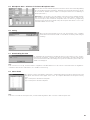
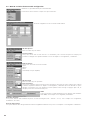
6.4 MCS 50 - Creation of a new Configuration
• Start the installed MCS-Editor Software via the “Programs” start menu.
• Choose the “File” menu and click the “New” command.
• Enter the desired configuration into the MCS-Editor mask.
Number of Stations
Enter the number of microphone units being used.
Button function
You can choose between PTT and ON/OFF function of the microphone button of all microphone units
(chairman and delegates). (Refer also to chapter “5.2 Configuration 3. Parameter”.)
Operation
You can choose between:
Request-to-talk
Autonomy
Override
(Automatic has no function)
Max. Chairman
Enter the number of chairman microphone units.
Chairman mode
You can adjust the priority button of the chairman microphone unit and choose between “Mute” and “Clear”
(refer also to chapter “5.2 Configuration 7. Parameter”). In the “Normal” mode the delegate microphone units
are switched off and the chairman microphone unit is switched on, when the priority button is pressed. After this
more delegates can switch on their microphone units.
NOM
You can adjust the max. number of switchable delegate microphone units (NOM).
Refer also to chapter “5.2 Configuration 6. Parameter”.
Speech time
You can enter the speech time of the delegate microphone units (hr.hr.-min.min.-sec.sec.). Refer also to chapter “5.2 Configuration 4. Parameter”.
Warning time
You can adjust the warning time of the illuminated ring in the microphone unit. Refer also to the chapter “5.2 Configuration 5. Parameter”.

43
english
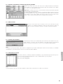
6.5 Microphone Data - Selection of Chairman Microphone Units
After the status check the chairman microphone unit can be selected. This is achieved by marking
the corresponding microphone unit and the “Chairman” panel. A delegate microphone unit can
be selected also as chairman. (Refer to chapter “1.2 Microphone units” and “1.3 Addressing of
the microphone unit”.)
Important: It is only possible to select the number of microphone units as chairman that have
been entered in the “Max. Chairman” panel before. In the “Mute Stations” panel you can
select the microphone units of which the loudspeakers have to be muted (e.g. neighbouring
microphone unit). This function should be used, if the microphone units stand too close to each
other and feedback sets in too early.
6.6 Saving
When you have entered all data, access the “File” menu and the “Save” command.
Enter a name for the file and click “OK”. You should also save when you have changed
something.
6.7 Downloading the Data
For downloading the entered data to the MCS 50 discussion control unit access the “Control”
menu and the “Download” command. The data are downloaded to the MCS 50 discussion
control unit. After this the MCS 50 is starting a new system check and if the system is “OK”, the
default screen will appear.
Note
If the connection is not set up, check the interface configuration in the MCS-Editor. Choose the “Diverse” menu item and the “Configuration”
command to define the free serial interface (set to “COM 2” at the factory).
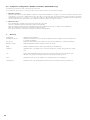
6.8 Status Check
Choosing the “Control” menu and the “Status Check” command all possible 32 microphone units are checked. All
microphone units that were found appear on the screen. The computer differentiates the microphone units by
types.
Type 1 = Microphone unit without loudspeaker
Type 2 = Microphone unit with loudspeaker
Note
If the PC does not indicate a microphone unit, check the addressing and the cable connection of that microphone unit.

44
6.9 Example for Configuration “Number of Stations” (MCS 50/64 only!)
In each line up to 32 stations can be connected to the control unit.
If for example 16 stations are to be connected in line 1 and 17 stations in line 2, you must do the following:
1. MCS Editor Software
Enter the number 64 into the field “Number of Stations”. Now you have 64 stations to configure: 1 to 32 in line 1 and 33 to 64 in line 2 that
is the stations 1 to 16 in line 1 and the stations 33 to 50 in line 2 (corresponds to the 17 microphone units connected in line 2). A possible
chairman station in line 2, e.g. station no. 7 corresponds to station no. 40 in the MCS Editor. Save the configuration and download the file
into the Control Unit. The control unit is now looking for 64 stations, but there are only 33 connected.
2. MCS Control Unit
Close the MCS Editor Software or disconnect the PC from the control unit.
Start the configuration with the multi-function buttons and LC-Display.
Enter the number of stations into the configuration menu (in this example 33). Refer also to chapter “5.2 Configuration”.
When the configuration is finished, the system works with 33 stations.
In the system check the control unit is looking for 33 stations and will find them.
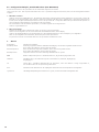
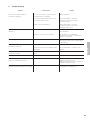
7. Glossary
Configuration Adjustment of all parameters.
Manufacturer specific Parameters which have been set at the factory and which can be changed. Press the reset button (6)
to load these parameters.
User specific Parameters which have been set from the user. Press the reset button (4) to load these parameters.
Operation specific Adjusted parameters and their change to operate the system.
NOM Number of Open Microphones which can be switched on simultaneously.
Parameter Adjustable values, e.g. Number of the connected microphones, operation mode, input level, output
level.
PTT Push-To-Talk = adjustable operation mode for the microphone unit, where the microphone unit is
switched on as long as the microphone button of the microphone unit is pressed.
Reset All parameters are reset to the original user or manufacturer specific configuration.
System Check Automatic check of all system parameters which is carried out when the system is switched on.

45
english
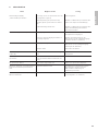
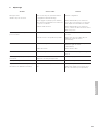
Problem
Error message “Wrong number of
microphones” displayed
No sound when the microphone units are
switched on
Distorted sound
Connection to PC is not set up
(MCS-Editor to MCS 50)
E.g. there are not more than 5
microphones working
All microphone units are flashing
Chairman unit does not work anymore after
reset (user + manufacturer specific)
No sound via integrated loudspeaker of the
microphone unit, but microphone is working
Possible Cause
Too few or too many microphone units as
configured in the configuration
The supply voltage and the address of the
microphone units is missing
Cable connection interrupted
Input switched off
Gain is too low on the selected input
Input overloaded
Defective cable
Wrong interface has been configured in the
MCS-Editor
Hotplugging has destroyed the data bus
driver
Microphone units have the same address
Chairman definition is missing
Insert function is activated
Solution
New configuration
Use the MCS-Editor to check the
microphone units (refer to chapter
“6.8 Status Check”)
Use the MCS-Editor to check the
microphone units and connect the
missing microphone unit
Use the MCS-Editor to switch on the input in
the configuration
Use the buttons of the MCS 50 to
increase the level of the concerning input
amplifier (8. Parameter)
Use the buttons of the MCS 50 to
decrease the sound of the concerning input
(10. Parameter)
Connect a new cable
Use the MCS-Editor to configure a new
interface
Contact the service or your dealer
Check the address of the microphone units
Configure the chairman microphone unit
with the MCS-Editor (refer to
chapter “6.5 Microphone data - Selection of
chairman microphone units”)
Switch off the insert function (refer to “5.2
Configuration 11. Parameter”)
8. Trouble Shooting

46
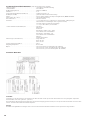
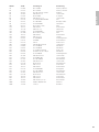
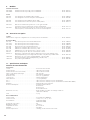
9. Versions
Discussion Control Unit
MCS 50/32 Discussion Control Unit for max. 32 microphone units . . . . . . . . . . . . . . . . . . . . . . . . . . . . Order # 459.275
MCS 50/64 Discussion Control Unit for max. 64 microphone units . . . . . . . . . . . . . . . . . . . . . . . . . . . . Order # 463.388
Microphone Units
MCS 501 Delegate microphone unit for mounting into a table . . . . . . . . . . . . . . . . . . . . . . . . . . . . . Order # 470.422
MCS 521 Delegate microphone unit with microphone button and loudspeaker . . . . . . . . . . . . . . . . . Order # 459.305
MCS 503 Chairman microphone unit for mounting into a table . . . . . . . . . . . . . . . . . . . . . . . . . . . . . Order # 470.430
MCS 523 Chairman microphone unit with microphone button and loudspeaker . . . . . . . . . . . . . . . . Order # 459.313
MCS 553 L System unit for mounting under the table with removable gooseneck microphone and
terminal strip for buttons and loudspeaker . . . . . . . . . . . . . . . . . . . . . . . . . . . . . . . . . . . . . Order # 471.119
MCS 563 L System unit for mounting under the table with terminal strip for microphone
LED ring, buttons and loudspeaker . . . . . . . . . . . . . . . . . . . . . . . . . . . . . . . . . . . . . . . . . . . Order # 471.127
10. Optional Accessories
Software
MCS Controller Operation and Configuration software for PC-control under Windows
®
. . . . . . . . . . . . . . . Order # 454.435
MCS-Accessories
CA 1241 Piezo button without description . . . . . . . . . . . . . . . . . . . . . . . . . . . . . . . . . . . . . . . . . . . . Order # 546.658
CA 1241 P Piezo button with “Prior” description . . . . . . . . . . . . . . . . . . . . . . . . . . . . . . . . . . . . . . . . . Order # 546.666
CA 1241 C Piezo button with “Clear” description . . . . . . . . . . . . . . . . . . . . . . . . . . . . . . . . . . . . . . . . Order # 546.674
CA 1242 Hubtaster mit integriertem zweifarbigen Leuchting. . . . . . . . . . . . . . . . . . . . . . . . . . . . . . . Order # 486.329
CA 1502 Connecting cable 15-pin Sub-D, 2.5 m long . . . . . . . . . . . . . . . . . . . . . . . . . . . . . . . . . . . . Order # 451.002
CA 1510 Connecting cable 15-pin Sub-D, 10 m long . . . . . . . . . . . . . . . . . . . . . . . . . . . . . . . . . . . . Order # 451.010
CA 1513 15-pin Sub-D, Y-adapter, 1 input, 3 outputs . . . . . . . . . . . . . . . . . . . . . . . . . . . . . . . . . . . . Order # 450.308
MCS 10 Transport case for 10 microphone units and discussion control unit . . . . . . . . . . . . . . . . . . Order # 466.948
MPC 22 E Acoustical boundary condenser microphone (semi-cardioid), black, without pre-amp,
for ceiling or table installation, for MCS 563 L . . . . . . . . . . . . . . . . . . . . . . . . . . . . . . . . . . Order # 465.194
SHM 214 E Gooseneck microphone, length 400 mm, plug-in type, with rigid tube (end piece)
XLR connector and illuminated ring, without pre-amp, for MCS 563 L . . . . . . . . . . . . . . . . Order # 464.635
SHM 215 E same as above, but length 500 mm . . . . . . . . . . . . . . . . . . . . . . . . . . . . . . . . . . . . . . . . . . Order # 464.708
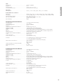
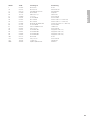
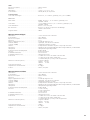
11. Technical Specifications
MCS 50 Discussion Control Unit
Connections
Mains. . . . . . . . . . . . . . . . . . . . . . . . . . . . . . . . . . . . . . . . IEC connector
RS 232 interface . . . . . . . . . . . . . . . . . . . . . . . . . . . . . . . 9-pin Sub-D-socket
Service RS 232 interface (front) . . . . . . . . . . . . . . . . . . . . 9-pin Sub-D-socket
Line-level inputs and outputs . . . . . . . . . . . . . . . . . . . . . . 3-pin XLR
Input level (Aux). . . . . . . . . . . . . . . . . . . . . . . . . . . . . . . . max. 250 mV, balanced
Output level (Audio Output) . . . . . . . . . . . . . . . . . . . . . . max. 1.55 V, balanced
Output Record . . . . . . . . . . . . . . . . . . . . . . . . . . . . . . . . . 250 mV, unbalanced
Input Extension . . . . . . . . . . . . . . . . . . . . . . . . . . . . . . . . 1.55 V, unbalanced
Microphone Line 1. . . . . . . . . . . . . . . . . . . . . . . . . . . . . . 15-pin Sub-D-socket, max. 32 microphone units
Microphone Line 2. . . . . . . . . . . . . . . . . . . . . . . . . . . . . . 15-pin Sub-D-socket, max. 32 microphone units (MCS 50/64 only!)
Display. . . . . . . . . . . . . . . . . . . . . . . . . . . . . . . . . . . . . . . LC-Display 2 x 16 characters
Switch - Button . . . . . . . . . . . . . . . . . . . . . . . . . . . . . . . . ON/OFF-switch
one Reset-Button for user specific adjustments
one N.o.m-Button
one Master-Reset-Button for manufacturer specific adjustments
Dimensions (W x H x D) . . . . . . . . . . . . . . . . . . . . . . . . . . 2 rack units high for desktop or 19" rack mounting (450 x 134 x 320 mm)
Weight. . . . . . . . . . . . . . . . . . . . . . . . . . . . . . . . . . . . . . . 5.7 kg
Power supply units
Mains voltage . . . . . . . . . . . . . . . . . . . . . . . . . . . . . . . . . 85 V to 264 V AC (50/60 Hz)
Output voltage . . . . . . . . . . . . . . . . . . . . . . . . . . . . . . . . +24 V, +5 V, +15 V, -15 V
Power consumption . . . . . . . . . . . . . . . . . . . . . . . . . . . . . 38 W (MCS 50/32)
60 W (MCS 50/64)
Output power at +24 V . . . . . . . . . . . . . . . . . . . . . . . . . . 6 A
Residual ripple . . . . . . . . . . . . . . . . . . . . . . . . . . . . . . . . . 150 mVpp
Ambient temperature. . . . . . . . . . . . . . . . . . . . . . . . . . . . 0°C to +50°C
Humidity . . . . . . . . . . . . . . . . . . . . . . . . . . . . . . . . . . . . . max. 90%
Protective measurements . . . . . . . . . . . . . . . . . . . . . . . . . overload, short circuit and open circuit proof

47
english
Audio
Frequency response . . . . . . . . . . . . . . . . . . . . . . . . . . . . . 80 Hz to 19,000 Hz
T.H.D.. . . . . . . . . . . . . . . . . . . . . . . . . . . . . . . . . . . . . . . . ≤ 1%
Power supply . . . . . . . . . . . . . . . . . . . . . . . . . . . . . . . . . . +24 V, +5 V, +15 V, -15 V
Power consumption at +24 V . . . . . . . . . . . . . . . . . . . . . 80 mA, 60 mA, 72 mA, 33 mA
XLR-plug
Line-output . . . . . . . . . . . . . . . . . . . . . . . . . . . . . . . . . . . Pin 2+, 3- and 1 screen, balanced, floating, 1.55 V (+6 dBm)
Microphone Line 1 and Line 2
AF-input. . . . . . . . . . . . . . . . . . . . . . . . . . . . . . . . . . . . . . 0 Ohm master, pin 7+, 6- and 14 screen, balanced, floating, adjustable -40 dB
AF-output . . . . . . . . . . . . . . . . . . . . . . . . . . . . . . . . . . . . 1.55 V (+6 dBm), Pin 5+, 4- and 12 screen, balanced, floating, adjustable -40 dB
Power supply output . . . . . . . . . . . . . . . . . . . . . . . . . . . . Pin 1 and 9 +24 V, 6 A
Data-Bus-line (CPU) . . . . . . . . . . . . . . . . . . . . . . . . . . . . . Pin 2 = A, Pin 3 = B, Pin 10 = screen
acc. to RS 485 standard
Max. cable length . . . . . . . . . . . . . . . . . . . . . . . . . . . . . . 300 m
MCS 521 Delegate Microphone Unit
Power supply . . . . . . . . . . . . . . . . . . . . . . . . . . . . . . . . . . +24 V, microphone line
Power consumption . . . . . . . . . . . . . . . . . . . . . . . . . . . . . max. 100 mA
AF-frequency response. . . . . . . . . . . . . . . . . . . . . . . . . . . 80 Hz to 19,000 Hz
T.H.D.. . . . . . . . . . . . . . . . . . . . . . . . . . . . . . . . . . . . . . . . ≤ 1%
Signal-to-noise ratio with microphone . . . . . . . . . . . . . . . ≥ 59 dB related to 1 Pa
AF-Output (+6 dBm) . . . . . . . . . . . . . . . . . . . . . . . . . . . . balanced, microphone line
AF-Output (-10 dBm) . . . . . . . . . . . . . . . . . . . . . . . . . . . . unbalanced, mini-jack (3.5 mm)
Limiter . . . . . . . . . . . . . . . . . . . . . . . . . . . . . . . . . . . . . . . compensates variations in speaking distance, cannot be switched off
Microphone . . . . . . . . . . . . . . . . . . . . . . . . . . . . . . . . . . . SHM 214 C 02 gooseneck microphone with illuminated ring, fixed
Loudspeakers. . . . . . . . . . . . . . . . . . . . . . . . . . . . . . . . . . wide-band, integrated loudspeaker
Volume control for loudspeaker-output . . . . . . . . . . . . . . 0 dB to -20 dB
1 button . . . . . . . . . . . . . . . . . . . . . . . . . . . . . . . . . . . . . Microphone-button
1 DIP-switch (No. 6) . . . . . . . . . . . . . . . . . . . . . . . . . . . . . no function
5 DIP-switches (No. 1 to 5) . . . . . . . . . . . . . . . . . . . . . . . Address of the microphone units (Binary code)
Connections. . . . . . . . . . . . . . . . . . . . . . . . . . . . . . . . . . . 1 x 3 m long cable with 15-pin Sub-D plug, microphone line
1 x 15-pin Sub-D socket, microphone line
1 x mini-jack (3.5 mm), documentation-output
Dimensions (without microphone) . . . . . . . . . . . . . . . . . . Length: 190 mm
Width: 155 mm
Height: 52 mm
Weight (without microphone) . . . . . . . . . . . . . . . . . . . . . 1500 g
Ambient temperature. . . . . . . . . . . . . . . . . . . . . . . . . . . . 0° - 50°C
Colour . . . . . . . . . . . . . . . . . . . . . . . . . . . . . . . . . . . . . . . Nextel
®
, stone grey
MCS 523 Chairman Microphone Unit
Power supply . . . . . . . . . . . . . . . . . . . . . . . . . . . . . . . . . . +24 V, microphone line
Power consumption . . . . . . . . . . . . . . . . . . . . . . . . . . . . . max. 100 mA
AF-frequency response. . . . . . . . . . . . . . . . . . . . . . . . . . . 80 Hz to 19,000 Hz
T.H.D.. . . . . . . . . . . . . . . . . . . . . . . . . . . . . . . . . . . . . . . . ≤ 1%
Signal-to-noise ratio with microphone . . . . . . . . . . . . . . . ≥ 59 dB related to 1 Pa
AF-Output (+6 dBm) . . . . . . . . . . . . . . . . . . . . . . . . . . . . balanced, microphone line
AF-Output (-10 dBm) . . . . . . . . . . . . . . . . . . . . . . . . . . . . unbalanced, mini-jack (3.5 mm)
Limiter . . . . . . . . . . . . . . . . . . . . . . . . . . . . . . . . . . . . . . . compensates variations in speaking distance, cannot be switched off
Microphone . . . . . . . . . . . . . . . . . . . . . . . . . . . . . . . . . . . SHM 214 C 02 gooseneck microphone with illuminated ring, fixed
Loudspeakers. . . . . . . . . . . . . . . . . . . . . . . . . . . . . . . . . . wide-band, integrated loudspeaker
Volume control for loudspeaker-output . . . . . . . . . . . . . . 0 dB to -20 dB
3 buttons. . . . . . . . . . . . . . . . . . . . . . . . . . . . . . . . . . . . . 1. Priority button
2. Microphone button
3. Clear button
1 DIP-switch (No. 6) . . . . . . . . . . . . . . . . . . . . . . . . . . . . . no function
5 DIP-switches (No. 1 to 5) . . . . . . . . . . . . . . . . . . . . . . . Addressing of the microphone units (Binary code)
Connections. . . . . . . . . . . . . . . . . . . . . . . . . . . . . . . . . . . 1 x 3 m long cable with 15-pin Sub-D plug, microphone line
1 x 15-pin Sub-D socket, microphone line
1 x mini-jack (3.5 mm), documentation output
Dimensions (without microphone) . . . . . . . . . . . . . . . . . . Length: 190 mm
Width: 155 mm
Height: 52 mm
Weight (without microphone) . . . . . . . . . . . . . . . . . . . . . 1500 g
Ambient temperature. . . . . . . . . . . . . . . . . . . . . . . . . . . . 0° - 50°C
Colour . . . . . . . . . . . . . . . . . . . . . . . . . . . . . . . . . . . . . . . Nextel
®
, stone grey
Page is loading ...
Page is loading ...
Page is loading ...
Page is loading ...
Page is loading ...
Page is loading ...
Page is loading ...
Page is loading ...
Page is loading ...
Page is loading ...
Page is loading ...
Page is loading ...
Page is loading ...
Page is loading ...
Page is loading ...
Page is loading ...
Page is loading ...
Page is loading ...
Page is loading ...
Page is loading ...
Page is loading ...
Page is loading ...
Page is loading ...
Page is loading ...
Page is loading ...
Page is loading ...
Page is loading ...
Page is loading ...
Page is loading ...
Page is loading ...
Page is loading ...
Page is loading ...
Page is loading ...
Page is loading ...
Page is loading ...
Page is loading ...
Page is loading ...
-
 1
1
-
 2
2
-
 3
3
-
 4
4
-
 5
5
-
 6
6
-
 7
7
-
 8
8
-
 9
9
-
 10
10
-
 11
11
-
 12
12
-
 13
13
-
 14
14
-
 15
15
-
 16
16
-
 17
17
-
 18
18
-
 19
19
-
 20
20
-
 21
21
-
 22
22
-
 23
23
-
 24
24
-
 25
25
-
 26
26
-
 27
27
-
 28
28
-
 29
29
-
 30
30
-
 31
31
-
 32
32
-
 33
33
-
 34
34
-
 35
35
-
 36
36
-
 37
37
-
 38
38
-
 39
39
-
 40
40
-
 41
41
-
 42
42
-
 43
43
-
 44
44
-
 45
45
-
 46
46
-
 47
47
-
 48
48
-
 49
49
-
 50
50
-
 51
51
-
 52
52
-
 53
53
-
 54
54
-
 55
55
-
 56
56
-
 57
57
-
 58
58
-
 59
59
-
 60
60
-
 61
61
-
 62
62
-
 63
63
-
 64
64
-
 65
65
-
 66
66
-
 67
67
-
 68
68
-
 69
69
-
 70
70
-
 71
71
-
 72
72
-
 73
73
-
 74
74
-
 75
75
-
 76
76
-
 77
77
-
 78
78
-
 79
79
-
 80
80
-
 81
81
-
 82
82
-
 83
83
-
 84
84


Beyerdynamic MCS 523 User manual
- Type
- User manual
- This manual is also suitable for
Ask a question and I''ll find the answer in the document
Finding information in a document is now easier with AI
in other languages
- français: Beyerdynamic MCS 523 Manuel utilisateur
- Deutsch: Beyerdynamic MCS 523 Benutzerhandbuch
Related papers
-
Beyerdynamic MCS 523 User manual
-
-
-
-
-
-
-
-
-
Other documents
-
Biamp MDS Microphone Discussion System User manual
-
Optimus DSC-50 User manual
-
Black Box ME800A User manual
-
Duravit D11100008 Operating instructions
-
LY International Electronics H-EX08 Owner's manual
-
Chiayo GM-243S(TL) Owner's manual
-
RCS PSS-224BVARES Owner's manual
-
-
-
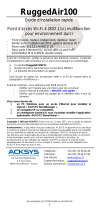 Acksys RuggedAir100 Quick Installation Manual
