RIDGID 975 Combo Roll Groover Change-out Operating instructions
- Type
- Operating instructions

975 Combo Roll Groover
Groove and Drive Roll Set Change-out Instructions
Kit Includes:
• 32838 Driveshaft for 2" - 8" Copper
• 30893 Driveshaft Key
• 32843 Groove Roll for 2" - 8" Copper
WARNING
Read and understand the threading machine and roll groover
operator’s manuals and instructions for all other equipment
being used before operating. Failure to follow all instruc-
tions may result in property damage and/or serious personal
injury.
Make sure the machine FOR/OFF/REV switch is in the OFF
position and the machine is unplugged before performing any
maintenance or making any adjustments.
SAVE THESE INSTRUCTIONS!
Contact Ridge Tool Technical Service De partment at (800)
519-3456 or [email protected] if you have any
questions.
Changing Roll Sets
When changing roll set parts, always make
sure drive and groove roll markings match. Mismatched
parts can make improper grooves and cause leaks.
Remove the roll groover from the power drive or threading
machine and place on a stable work bench.
Required Tools:
•
3
/
8
" Hex Wrench
•
3
/
32
" Hex Wrench
• .070" External Retaining Ring Pliers
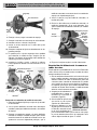
Removing and Installing Drive Roll
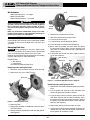
1. Remove 6 screws that hold rear cover to the housing.
2. Remove the rear cover
(See Figure 1)
.
Figure 1 – Removing Rear Cover
3. Remove pinion.
4. Remove the driveshaft assembly out of the back of the
975 Roll Groover.
5. Remove retaining ring from driveshaft and slide gear off.
(See Figure 2.)
Figure 2 – Removing Retaining Ring
6. Remove key and then thrust washer.
7. Slide thrust washer onto new driveshaft.
8. Insert key and install gear.
9. Install retaining ring into driveshaft groove.
10. Place driveshaft assembly into main housing.
11.Grease from the gearbox may have been lost during
the driveshaft change. Make sure the bearings and
gear teeth are coated sufficiently with a good general
purpose grease.
12. Insert pinion and reinstall rear cover. Tighten screws to
12-16 ft
*
lbs of torque.
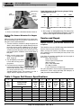
Figure 3 – 975 Combo Roll Groover Parts Diagram
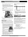
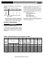
Removing and Installing Groove Roll
1. Remove the setscrew that holds the groove roll shaft in
place.
2. Pull the groove roll shaft out of the slide block and
remove the groove roll and thrust washer.
3. Insert the thrust washer and new groove roll into the
slide block. Ensure that the internal retaining ring in
the groove roll is closest to the main housing, and that
the groove roll is between the thrust washer and main
housing.
(See Figure 4.)
4. Replace the groove roll shaft and the set screw.
5. Visually inspect the alignment between the groove roll
and the drive roll. If they are not aligned, check orienta-
tion of groove roll and thrust washer.
Ridge Tool Company/Elyria, Ohio, U.S.A.
3/09
058-005-726.10
NOTICE
Gear
Thrust
Washer
Retaining Ring
Main Housing
Pinion
Driveshaft
Rear Cover
Gear
Screws
Retaining Ring
Thrust
Washer
Key
Rear Cover

Ridge Tool Company/Elyria, Ohio, U.S.A.
2
975 Combo Roll Groover
Groove and Drive Roll Set Change-out Instructions
Figure 4
6. Grease as directed in
Lubrication Section
of manual.
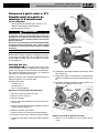
Setting The Groove Diameter For Copper
Tubing
When using the 975 Combo Roll Groover for copper tube,
the groove depth gauge on the groover cannot be used. It
will give incorrect groove diameters.
1. Turn the feedscrew clockwise to bring the groove roll
down in contact with the pipe outside diameter, then turn
the feedscrew one quarter additional turn. The adjust-
ing screw may need to be loosened (turned counter-
clockwise) to allow the groove roll to contact pipe. The
pipe and roll groover should be se cure to each other at
this point.
2. Make sure the groove depth
gauge is in the grooving po -
sition.
(Figure 5)
3. Turn the adjusting screw until it
is flush with the top plate of
the groover.
4. Find the diameter and type of
pipe to be grooved on Table A
and back the adjusting screw
off the top plate the corre-
sponding number of turns. For example, for 4" Sch. L
copper, back the adjustment screw 1
1
/
4
turns.
5.
Go to step 4 of “Setting/Measuring The Groove Dia -
meter” in the 975 Combo Groover operator’s manual. In
step 6 use the Copper Roll Groove Specifications.
Service and Repair
WARNING
Improper service or repair can make machine unsafe
to operate.
Tool should be taken to a RIDGID Independent Author ized
Service Center or returned to the factory.
When servicing this machine, only identical replacement
parts should be used. Use of other parts may create a risk
of serious injury.
If you have any questions regarding the service or repair of
this machine, call or write to:
Ridge Tool Company
Technical Service Department
400 Clark Street
Elyria, Ohio 44035-6001
Tel: (800) 519-3456
E-mail: T[email protected]
For name and address of your nearest Independent Author -
ized Service Center, contact the Ridge Tool Com pany at
(800) 519-3456 or www.RIDGID.com
Chart A – Depth Adjustment for Roll Grooving Copper
Tubing
Depth Adjustment for Roll Grooving Copper Tubing
(Adjusting Screw Turns)
Dia. K L M DWV
2-2.5"
7
/
8
7
/
8
5
/
8
5
/
8
3" 1
1
/
16
1
1
/
16
1
1
/
16
1
1
/
16
4" 1
1
/
4
1
1
/
4
1
1
/
4
1
1
/
8
5" 1
1
/
2
1
1
/
2
1
1
/
2
1
1
/
2
6" 1
13
/
16
1
3
/
4
1
3
/
4
1
3
/
4
8" 2
1
/
2
2
3
/
8
2
1
/
8
2
1
/
8
Figure 5 – Gauge In
Grooving Position
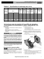
Table I. Copper Roll Groove Specifications
1 2 345678
AB CDT
Nom. Tubing Outside Gasket Groove Groove Groove Min. Max.
Size Diameter O.D. Seat Width Dia. Depth Allow. Allow.
Inches A +.03 +.00 Ref.
1
Wall Flare
Basic Tolerance ±0.03 –.000 –.02 Thick. Dia.
2" 2.125 ±0.002 0.610 0.300 2.029 0.048 DWV 2.220
2
1
/
2
" 2.625 ±0.002 0.610 0.300 2.525 0.050 0.065 2.720
3" 3.125 ±0.002 0.610 0.300 3.025 0.050 DWV 3.220
4" 4.125 ±0.002 0.610 0.300 4.019 0.053 DWV 4.220
5" 5.125 ±0.002 0.610 0.300 5.019 0.053 DWV 5.220
6" 6.125 ±0.002 0.610 0.300 5.999 0.063 DWV 6.220
8" 8.125 +0.002/-0.004 0.610 0.300 7.959 0.083 DWV 8.220
1. Nominal Groove Depth is provided as a reference dimension. Do not use groove depth to determine groove acceptability.
Main Housing
Set Screw
Thrust
Washer
Groove
Roll
Slide
Block
Page is loading ...
Page is loading ...
Page is loading ...
Page is loading ...
Page is loading ...
Page is loading ...
-
 1
1
-
 2
2
-
 3
3
-
 4
4
-
 5
5
-
 6
6
-
 7
7
-
 8
8


RIDGID 975 Combo Roll Groover Change-out Operating instructions
- Type
- Operating instructions
Ask a question and I''ll find the answer in the document
Finding information in a document is now easier with AI
in other languages
Related papers
-
RIDGID Ranuradora de rodillo combinada 975 User manual
-
RIDGID 916 Roll Groover User manual
-
-
-
RIDGID 300 User manual
-
RIDGID 23498 Specification
-
RIDGID 300 Compact User manual
-
RIDGID 30118 User manual
-
-
Other documents
-
Emerson B-294 HD User manual
-
Ega Master RANUMATIC COMBI UNIVERSAL 56032 Owner's manual
-
REED RGCOMBO2 User manual
-
-
-
REED RG6CU User manual
-
Crain 968 Owner's manual
-
 Rigid Industries 535-A User manual
-
Ford Meter Box DMBB-67 Installation guide
-
Makita CA5000X User manual
