
PRIMECARE
®
Sit to Stand Lift
OWNER’s MANUAL
DEALER: This manual must be given to the user of the patient lift.
USER: Before using this patient lift, read this manual and save for future reference.
SERVICE AGENT: Only Drive DeVilbiss Healthcare authorized service agents are
permitted to install, service or repair DRIVE product.
Items#
STSP450 (Power Base)
STSM450 (Manual Base)

Page1
The information in this document is subject to change without notice
Owner's Manual
REV2.7.14.20
TABLE OF CONTENTS
STANDARD SYMBOLS USED IN THIS MANUAL .......................................................................... 3
INTENDED USE ........................................................................................................................... 4
CONTRA-INDICATIONS ............................................................................................................ 4
GENERAL SAFETY ...................................................................................................................... 5
ELECTROMAGNETIC EMISSION AND IMMUNITY ...................................................................... 8
FEATURES AND BENEFITS ..........................................................................................................11
TECHNICAL SPECIFICATIONS ..................................................................................................12
COMPLIANCE INFORMATION .................................................................................................13
UNPACKING INSTRUCTIONS ....................................................................................................13
ASSEMBLY ................................................................................................................................14
OPERATION ..............................................................................................................................18
BATTERY INFORMATION ...........................................................................................................26
CARE AND MAINTENANCE .....................................................................................................27
SERVICING ...............................................................................................................................29
TROUBLESHOOTING GUIDE .....................................................................................................31
WARRANTY ..............................................................................................................................32
END OF LIFE DISPOSAL ............................................................................................................33
NOTE: DO NOT operate this product without first reading and understanding this user
manual. Damage or injury may result from improper use of this product.

The information in this document is subject to change without notice
Page2
Owner's Manual
REV2.7.14.20
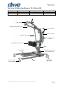
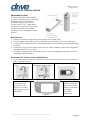
The Drive DeVilbiss Healthcare’s Sit to Stand Lifts
Product#
Product Name
Power/Manual Base
Weight Capacity
STSP450
Sit to Stand Lift
Power
450lbs
STSM450
Sit to Stand Lift
Manual
450lbs
Push Handle
Handgrip
Sling Attachment Hook
Adjustable Knee Pad
Footplate
Mast
Front Caster
(Non-Braking)
Battery/Control
Pack
Electric Actuator
Rear Caster
(Braking)
Base
Hand Control
Electric or Manual
Leg Operations

Page3
The information in this document is subject to change without notice
Owner's Manual
REV2.7.14.20
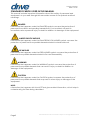
STANDARD SYMBOLS USED IN THIS MANUAL
This manual includes important information about the safety of personnel and
equipment. As you read through this manual be aware of the symbols and their
meanings.
DANGER
Information that appears under the DANGER symbol concerns the protection of
personnel from direct and pending hazards that, if not avoided, will result in
immediate, serious personal injury or death in addition to damage of the equipment.
DANGER SHOCK HAZARD
Information that appears under the DANGER SHOCK HAZARD symbol concerns the
protection of personnel from possible hazards related to electrical shock.
FIRE HAZARD
Information that appears under the FIRE HAZARD symbol concerns the protection of
personnel from possible hazards related to fire and flammability.
WARNING
Information that appears under the WARNING symbol concerns the protection of
personnel from possible hazards that can result in injury or death in addition to
damage of the equipment.
CAUTION
Information that appears under the CAUTION symbol concerns the protection of
personnel from possible hazards that may result in minor injury or damage of the
equipment.
NOTE:
Information that appears with the NOTE text gives added information, which helps in
understanding the item being described.

The information in this document is subject to change without notice
Page4
Owner's Manual
REV2.7.14.20
PRODUCT SYMBOLS
Symbols
Description
Symbols
Description
Type B applied part
equipment.
Intertek’s ETL listed mark for US and Canada.
A product bearing the ETL listed Mark is
determined to have met the minimum
requirements of prescribed product safety
standards.
According to IEC 60529. This
lift is identified as equipment
that is protected against
solid foreign objects of 12,5
mm and greater and
splashing water.
The symbol required to be displayed on
regulated products for sale on the European
Market. It indicates that the product complies
with applicable European Directives related to
health, safety, environment and consumer
protection.
The owner’s manual must
be read before operating
the bed.
The disposal of electronics should not be
mixed with general household waste
Maximum safe working
load.
For indoor use.
Combined mass + SWL
INTENDED USE
The intended use of this lifting device is for the safe lifting and transfer of an
individual from one resting surface to another (such as a bed to a wheelchair). Drive
DeVilbiss Healthcare recommends that the transfer of a patient is fully risk assessed
and conducted safely over a short distance only.
The lift is a battery powered, mobile electric sit to stand lift intended for individuals at
home, hospital and institutional healthcare environment use, the lift is indoor use only.
The lift designed to support and promote safe patient handling and transfer for both
the patient and caregiver.
The lift incorporates a 4-point hook as standard and is designed to be used in
conjunction with, and only Drive DeVilbiss branded range of slings.
Note: The caregiver must only use two hooks at one time and they must be on the
same level. The farther away two hooks are for a shorter person, closer hooks are for
a taller person.
CONTRA-INDICATIONS
This lift should not be operated (control the movements of the lift through the control
interfaces)by persons who do not have the cognitive skills to understand the
information in the owner’s manual or cannot understand and perform the proper
operation of the lift.
This Lift should not be used by persons who are not able to support the majority of
their own weight.
This lift should not be used or operated by children.

Page5
The information in this document is subject to change without notice
Owner's Manual
REV2.7.14.20
GENERAL SAFETY
WARNING
• Check all parts for shipping damage before using. In case of damage, DO NOT use
the equipment. Contact the Drive DeVilbiss Healthcare for further instructions.
• DO NOT operate this lift without first reading and understanding the warnings,
cautions and instructions in this manual. If you are unable to understand the
warnings, cautions, and instructions, contact a healthcare professional, dealer or
technical personnel if applicable before attempting to use this lift-otherwise injury
or damage may result.
• Drive DeVilbiss Healthcare patient lifts may be safely operated by a single
appropriately trained and experienced caregiver, in accordance with ISO
10535:2006. However, there are circumstances (including but not limited to the
patient’s medical, psychological or behavioral condition, as well as the caregiver’s
training, experience or physical limitations) that may require two people to safely
operate the lift. It is the responsibility of each facility or caregiver to determine if
more than one person is required to safely operate the lift at the time of transfer,
depending on these circumstances. It is also the responsibility of each facility or
caregiver to ensure that the lift is only operated without additional assistance, if
circumstances safely allow, by someone who: (1) has thoroughly studied the
instructions for use for both the lift and any accessories; (2) has adequate training
and experience to determine that the lift may be safely operated without
additional assistance; and (3) can operate the lift without assistance.
• DO NOT use the sling in combination with the lift as a transport device. It is
intended to transfer an individual from one resting surface to another (such as a
bed to a wheelchair).
• DO NOT attempt any transfer without approval of the patient’s physician, nurse or
medical assistant. Thoroughly read the instructions in this Instruction manual,
observe a trained team of experts perform the lifting procedures and then perform
the entire lift procedure several times with proper supervision and a capable
individual acting as a patient.
• Individuals that use the sling MUST be able to support the majority of their own
weight, otherwise injury can occur.
• DO NOT exceed maximum weight limitation of the Lift. The maximum weight
limitation is 450 lbs. regardless of any additional weight limitations on accessories.
• DO NOT raise the patient to a full standing position while using the sling otherwise
injury can occur.
• When lifting patient, make sure the base legs are in the most widely opened
position and the rear caster are unlock. Otherwise, the lifter may tilt over.
• Before positioning the legs of the lift around the patient, make sure the patient’s
feet are out of the way of the footplate, otherwise injury can occur.

The information in this document is subject to change without notice
Page6
Owner's Manual
REV2.7.14.20
WARNING
• Drive DeVilbiss Healthcare’s slings and patient lift accessories are
specifically designed to be used in conjunction with DRIVE’s patient lifts.
Slings and accessories designed by other manufacturers are not to be
utilized as a component of DRIVE’s lift system. Use of these products is
prohibited and will void DRIVE’s patient lift warranty. Use only DRIVE’s slings
and patient lift accessories to maintain patient safety and product utility.
• ALWAYS check the sling is suitable for the particular patient and is of the
correct size and capacity
• Before lifting the patient, make sure the bottom edge of the sling is
positioned on the lower back of the patient and the patient's arms are
outside the sling.
• The belt of Sling MUST be snug, but comfortable on the patient, otherwise
the patient can slide out of the sling during transfer, possibly causing injury.
• ENSURE sling loops are pulled completely and rest securely on hooks
• NEVER use a sling, which is frayed or damaged
• When elevated a few inches off the surface being transferred from and
before moving the patient, check again to make sure that the sling is
properly connected to the attachment points of the lift. If any attachments
are NOT properly in place, lower the patient back onto the surface and
correct this problem.
• NEVER operate the lift with loose or missing parts or fasteners.
• Use push handle on the mast at ALL times to push or pull the lift
• DO NOT roll lift over deep carpet, raised carpet bindings or any uneven
surfaces which may cause lift to lose its balance.
• DO NOT bump the lift down steps, loaded or unloaded.
• DO NOT push a loaded lift at speeds, which exceed a slow walking pace
(2.6 ft/sec)
• DO NOT park a loaded lift on ANY sloping surface.
• DO NOT use or store in a wet or corrosive environment: shower, bath or pool
locations.
• DO NOT attempt to negotiate a slope without a second helper being
present.
• Push the “Emergency” red button if the control unit system is out of control.

Page7
The information in this document is subject to change without notice
Owner's Manual
REV2.7.14.20
WARNING
• DO NOT attempt to negotiate a loaded lift on a slope, which exceeds 1:12
(aprox. 5 degrees)
• The battery must be connected to an appropriate power source when loss
of power source would result in an unacceptable risk
• DO NOT charge batteries in a bathroom or shower room.
• DO NOT place or store batteries under direct sunlight or near a heat source.
• Maintenance MUST be performed ONLY by qualified personnel.
• Regular maintenance of the Lift and accessories is necessary to assure
proper operation.
• Do not modify this lift without authorization of the manufacturer. If
unauthorized service is performed on any components the warranty is void
DANGER SHOCK HAZARD
• DO NOT roll the lift over any power or pendant cords.
• DO NOT open any actuators, control boxes, pendants or battery. Service
and repair must only to be performed by authorized service personnel. If
unauthorized service is performed on any components the warranty is void.
• DO NOT allow the cord, electrical outlets, and electrical control box or
hand pendant to become wet or submerged.
• DO NOT operate the lift if any electrical component such as the electrical
outlet, connections, motor/actuator, battery or mechanical component
has malfunctioned or has been damaged in any way.
• To avoid risk of electric shock, this equipment must only be connected to
supply mains with protection earth when charging.
FIRE HAZARD
• DO NOT use near open flame or explosive gases.
• This lift should not be placed in an oxygen enriched environment.

The information in this document is subject to change without notice
Page8
Owner's Manual
REV2.7.14.20
CAUTION
• Drive DeVilbiss Healthcare recommends locking the rear swivel casters
ONLY when positioning or removing the sling from around the patient
• Drive DeVilbiss Healthcare does NOT recommend locking the rear swivel
casters of the lift when lifting and transferring an individual. Doing so could
cause the lift to tip and endanger the patient and assistants. Drive DeVilbiss
Healthcare does recommend that the rear swivel casters be left unlocked
during lifting and transferring procedures to allow the lift to stabilize itself
when the patient is initially lifted from and transferred to a chair, bed or any
stationary object
• This lift frame complies with EMC requirements of IEC 60601-1-2. Radio
transmitting equipment, cell phones or similar electronic devices, used in
proximity of the lift, may affect the lifts performance.
• Pinch Points: Feet and hands could be pinched. Keep feet and hands
away from the pinch points.
ELECTROMAGNETIC EMISSION AND IMMUNITY
This MEDICAL ELECTRICAL EQUIPMENT needs special precautions regarding EMC and
needs to be installed and put into service according to the EMC information
provided in the table below.
Portable and mobile RF communications equipment can affect MEDICAL
ELECTRICAL EQUIPMENT
WARNING
The use of ACCESSORIES, transducers and cables other than those specified, with
the exception of transducers and cables sold by the manufacturer of the
EQUIPMENT or SYSTEM as replacement parts for internal components, may result in
increased EMISSION or decreased IMMUNITY of the EQUIPMENT or SYSTEM.
WARNING
The ME EQUIPMENT or SYSTEM should not be used adjacent to or stacked with other
equipment and that if adjacent or stacked use is necessary, the ME EQUIPMENT or
SYSTEM should be observed to verify normal operation in the configuration in which it
will be used.

Page9
The information in this document is subject to change without notice
Owner's Manual
REV2.7.14.20
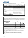
DECLARATION - ELECTROMAGNETIC EMISSIONS
Guidance and manufacturer's declaration - Electromagnetic emissions
The Prime Care™STSP450, STSM450 is intended for use in the electromagnetic environment
specified below. The customer or the user of the Prime Care™ STSP450, STSM450 should
ensure that it is used in such an environment.
Emissions Test
Compliance
Electromagnetic environment - Guidance
RF Emissions CISPR 11
Group 1
The Prime Care™ STSP450, STSM450 uses RF energy
only for its internal function. Therefore, its RF
emissions are very low and are not likely to cause
any interference in nearby electronic equipment.
RF Emissions
CISPR 11
Class B
Harmonic Emissions
IEC 61000-3-2
Class A
The Prime Care™ STSP450, STSM450 is suitable for
use in all establishments including domestic
establishments and those directly connected to
the public power supply network that supplies
buildings used for domestic purposes.
RF emissions
CISPR 14-1
Complies
The Prime Care™ STSP450, STSM450 is not suitable
for interconnection with other equipment.
RF emissions
CISPR 15
Complies
Recommended separation distances between portable and mobile
RF communications equipment and the Prime Care™STSP450,STSM450
The Prime Care™ STSP450, STSM450 is intended for use in the electromagnetic environment in which radiated RF
disturbances are controlled. The customer or the user of the Prime Care™ STSP450, STSM450 can help prevent
electromagnetic interference by maintaining a minimum distance between portable and mobile RF
communications equipment (transmitters) and the Prime Care™ STSP450, STSM450 as recommended below,
according to the maximum output power of the communications equipment.
Rated maximum output
power
of transmitter
W
Separation distance according to frequency of transmitter
m
150 kHz to 80 MHz
80 MHz to 800 MHz
800 MHz to 2,5
GHz
0.01
0.12
0.12
0.23
0.1
0.38
0.38
0.73
1
1.2
1.2
2.3
0.1
0.38
0.38
0.73
10
3.8
3.8
7.3
100
12
12
23
For transmitters rated at a maximum output power not listed above, the recommended
separation distance d in meters (m) can be estimated using the equation applicable to the
frequency of the transmitter, where P is the maximum output power rating of the transmitter
in watts (W) accordable to the transmitter manufacturer.
NOTE1: At 80 MHz and 800 MHz the separation distance for the higher frequency
range applies
NOTE2: These guidelines may not apply in all situations. Electromagnetic
propagation is affected by absorption and reflection from structures, objects and
people.

The information in this document is subject to change without notice
Page10
Owner's Manual
REV2.7.14.20
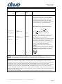
Guidance and manufacturer's declaration: Electromagnetic Immunity
The Prime Care™ STSP450, STSM450 is intended for use in the electromagnetic environment specified below. The
customer or the user of the Prime Care™ STSP450, STSM450 should ensure that it is used in such an environment.
Immunity test
IEC 60601 test
level
Compliance
level
Electromagnetic environment - guidance
Conducted
RF
IEC 61000-4-6
Radiated RF
IEC
61000-4-3
3 Vrms
150 kHz to 80
MHz
3 V/m
80 MHz to 2.5
GHz
10 V
10 V/m
Portable and mobile RF communications
equipment should be used no closer to
any part of the Prime Care™ STSP450,
STSM450, including cables, than the
recommended separation distance
calculated from the equation applicable
to the frequency of the transmitter.
Recommended separation distance
80MHz to 800MHz
800MHz to 2,5GHz
Where P is the maximum output power
rating of the transmitter in watts (W)
according to the Transmitter
manufacturer and d is the recommended
separation distance in meters (m). Field
strengths from fixed RF transmitters, as
determined by an electromagnetic site
survey,
a
should be less than the
compliance level in each frequency
range.
b
Interference may occur in the vicinity of
equipment marked with the following
symbol:
NOTE1: At 80MHz and 800MHz the higher frequency range applies.
NOTE2: These guidelines may not apply in all situations. Electromagnetic propagation is
affected by absorption and reflection from structures, objects and people.
a
Field strengths from fixed transmitters, such as base stations for radio (cellular/cordless)
telephones and land mobile radios, amateur radio, AM and FM radio broadcast and TV
broadcast cannot be predicted theoretically with accuracy. To assess the electromagnetic
environment due to fixed RF transmitters, an electromagnetic site survey should be
considered. If the measured field strength in the location in which the Prime Care™ STSP450,
STSM450 is used exceeds the applicable RF compliance level above, the Prime Care™
STSP450, STSM450 should be observed to verify normal operation. If abnormal performance is
observed, additional measures may be necessary, such as reorienting or relocating the Prime
Care™ STSP450, STSM450.
b
Over the frequency range 150 kHz to 80 MHz, field strengths should be less than 10 V/m.

Page11
The information in this document is subject to change without notice
Owner's Manual
REV2.7.14.20
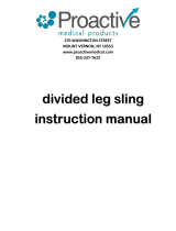
FEATURES AND BENEFITS
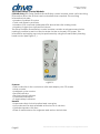
Lift Serial Numbers
When ordering parts or when contacting Drive DeVilbiss Healthcare Customer
Service Department, please include lift's model and serial numbers, found on the
identification labels as below. The identification labels are located on the legs of lift
base
9W: Factory Code
YY : Manufacturing Year (two digits)
MM: Manufacturing Month (two digits)
######: Six Sequential Digits
➢ Provides stable assistance in standing, transferring
and toileting.
➢ Four sling attachment hooks enable the lift to
accommodate a variety of sling designs.
➢ Extra-wide, non-skid footplate provides a stable
base for foot positioning.
➢ Soft, padded adjustable leg support.
➢ Easy-roll 4" rear casters and 3" front casters mean
stability and easy maneuverability over a variety of
surfaces.
➢ 24V DC motor provides power and reliability.
➢ Motor has an emergency stop button and manual
lowering feature.
➢ Visual battery fuel indicator on hand control.
➢ Audible Alert if the lift is low battery power.
➢ Can be charged on, or off the lift.
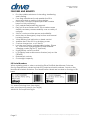
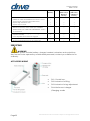
➢ Includes removable, rechargeable battery (Figure
A) , wall mount charger(Figure B) and external
charging cradle (Figure C) (optional).
➢ Smart/Safety control module.
➢ LCD Display and maintenance feature (only on the
STSP450)
➢ Redundant controls
➢ Overweight capacity
Figure A
Figure C
Figure B

The information in this document is subject to change without notice
Page12
Owner's Manual
REV2.7.14.20
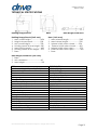
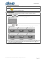
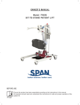
TECHNICAL SPECIFICATIONS
Hoisting Range/Reach
Base
Base Height/Clearance
Hoisting Range/Reach (Unit: mm)
1. Max overall height...................1494
2. Height at Max reach................956
3. Min overall height.....................780
4. Hoisting reach at Max height...381
5. Max hoisting reach....................632
6. Hoisting reach at Min height....593
7. Base
Base (Unit: mm)
1. Max external length.....................1069
2. Max internal length.......................780
3. Internal width when closed.........534
4. External width when closed........623
5. Internal width when open.............972
6. External width when open............1061
7. Base
Base height/clearance (Unit: mm)
1. Base
2. Min clearance...........................69
3. Max height..................................120
ITEM
SPECIFICATION
Maximum Weight Capacity (SWL)**
450 lbs (204kg)
Product Weight
148 lbs (67kg)
Castors
3"(Front)4"(Rear)
Brakes
Yes – Rear
Charger Input
100 - 240 VAC,50/60 Hz
Charger Output
28 VDC, 1.5 A
Maximum noise measured(sound level)
less than 65DB
Protective Earth Ground
Internally powered
Electrical Shock Protection
TYPE B
Enclosure Protection
IP24
Duty cycle
Min. 2min (on)/ Max. 18min (off)
Motor Anti-Entrapment
Yes
Emergence Stop
Yes
Emergence Lowering
Yes
Battery Model
BAT
Battery Type
Lead-Acid
Battery Capacity
2.9 or 5Ah
Battery Input voltage
29~45V DC
Battery Output voltage
24V DC, 2.9A or 5A

Page13
The information in this document is subject to change without notice
Owner's Manual
REV2.7.14.20
COMPLIANCE INFORMATION
Matching the correct lift components to meet regulatory specifications can be
complicated. Drive DeVilbiss Healthcare offers a wide variety of compliance options
and we can assist your facility in selecting components or accessories that are
recommended for the specific lift model.
GENERAL INFORMATION
The recommended environment for operation and storage/transportation of the lift
is listed below:
Operation
Storage/Transportation
Ambient temperature:
10°C ~ 36°C (50°F~96.8°F)
-10°C ~ 50°C (14°F~122°F)
Relative humidity range:
30% ~ 75%
20% ~ 95%
Atmospheric pressure:
86KPa~ 106Kpa
70KPa~ 106KPa
This lift is classified for intermittent operation. Lift may be operated for 2 minutes out
of every 20 minutes.
APPLIED PARTS LIST
• Lift Frame
• Pendant
• Handgrip
• Knee pad
MATERIALS ACCESSIBLE TO USER
• Surface Coating: Powder Coating
• Color of Powder: Grey
• Pendant Housing: ABS
• Surface of Handgrip: PVC
• Surface of Knee pad : PU
UNPACKING INSTRUCTIONS
CAUTION
Unpack the lift in an area with sufficient room to work. Do not allow patients near the
lift until it has been completely set up and the work area has been cleared of all
debris.
1. Inspect the lift for shipping damage. If the lift is damaged, do not use lift and
immediately contact Drive DeVilbiss Healthcare for further instruction.
2. Verify the proper lift model was shipped. If you feel there was a mistake, do
not use lift and immediately contact Drive DeVilbiss Healthcare for further
instruction.
3. After verifying you’ve received the correct device without damage, cut
strapping around box and remove enclosing lift.
NOTE: If the carton is in an upright position, slowly lower to the floor. It may be
necessary for two or more people to help in lowering the lift.
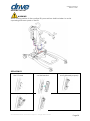
4. Inspection of All Components - Receipt of assembled lift, the carton contains:
• Sit to Stand Lift: Mast, Boom, Base, Footplate , Knee pad ,Battery /Control
Pack;
• Wallet containing documents;
• Handset;
• Charger;
• Shifter Handle (for those lifts that have a manual base).

The information in this document is subject to change without notice
Page14
Owner's Manual
REV2.7.14.20
ASSEMBLY
KNOWLEDGE/SKILLS REQUIRED
• Ability to read and understand
owner’s manual
• Ability to manipulate required
tools
• Basic mechanical aptitude
TOOLS REQUIRED
• Philips Screwdriver
• Adjustable Wrench
• Allen Wrench #13,14,16,18,20
WARNING
• Installation MUST be performed ONLY by qualified personnel.
• Avoid trapping fingers. Keep fingers away from the end of the mast when
inserting into the base socket. Full engagement of the mast is indicated by the
label on the side of the mast. The electric leg operation will not function unless
the mast is fully engaged.
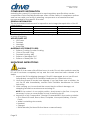
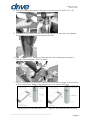
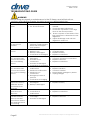
1. Remove all the parts from the carton and place on the floor, taking care to
protect the finish from damage.
2. Place the base in a clear space and apply the rear brakes. If you are
assembling a unit with a power base, connect the two power base
connectors before sliding mast into base. Be careful to not damage the wire
connectors.
3. Fit the mast into the base socket.

Page15
The information in this document is subject to change without notice
Owner's Manual
REV2.7.14.20
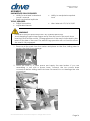
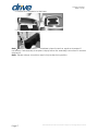
4. Secure the mast to the base with four hex screws(5/16"-18*5/8")and one hex
set screw(1/4"-20*1/2").
5. If you are assembling the manual base, connect the manual leg adjustment
shifter handle to the base with one hex set screw (1/4"-20*1/2")
6. Put one nylon gasket on each side of the boom end, and fit the boom into
the mast.
7. Secure the boom to the mast with one hex bolt (1/2"-13*1 3/4").

The information in this document is subject to change without notice
Page16
Owner's Manual
REV2.7.14.20
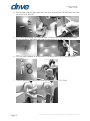
8. Secure the lifting actuator to the boom with the hex bolt (3/8"-16*2 1/4").
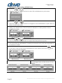
9. Install the control box onto the mounting bracket on the mast, and tighten
the control box with two mounting screws (M4).
10. Fit battery to control box and make sure the latch holding the battery in
place is fully engaged “Click” in place.
11. Plug the handset and actuator cables into the socket located on the bottom
side of control box. Refer to the figures below for correct positions.
Figure D (for Power Base unit only) Figure E (for Manual base unit only)

Page17
The information in this document is subject to change without notice
Owner's Manual
REV2.7.14.20
12. Attach the footplate to the base
13. Attach the kneepad to the kneepad receiver
Note
:
The lift should not be disassembled unless for service, repair or transport if
necessary. If disassembly is required, simply follow the assembly instructions in reverse
sequence.
Note: Please always check the mast is fully locked into position.

The information in this document is subject to change without notice
Page18
Owner's Manual
REV2.7.14.20
OPERATION
WARNING
Always check the following before operation:
• The mast is fully locked into position.
• Confirm the boom rises and lowers (This is done via the hand control).
• The legs of the lift open and close satisfactorily (This is done via the hand
control or shifter handle).
• Prior to first use, please make sure that the battery has been charged for 24
hours in order to reach proper function and prolong the lifetime of battery.
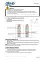
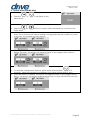
Locking/Unlocking the Rear Swivel Casters
Raising and Lowering the Lift
• Raising the lift -Press the (M1) UP button on the hand control to raise the lift arms
and the patient.
• Lowing the lift -Press the (M1) DOWN button on the hand control to lower the lift
arms and the patient.
NOTE: If the Lift is in the full UP position, it may be necessary to pull down slightly on
the lift arms before the mast will lower.
Closing/Opening the Leg Base
Electric leg adjustment (STSP450)
• Opening the leg base- Pressing the (M2) left button widens the leg base;
• Closing the leg base-Pressing the (M2) right button closes the leg base.
Manual leg adjustment (STSM450)
• Opening/Closing the leg base-lowering on the shifter handle
• Locking - Press DOWN on the bottom of the
locking lever.
• Unlocking -Press DOWN on the top of the
locking lever.
Definitions: M1 -Actuators for Lifting; M2 -Actuators for Leg Adjustments

Page19
The information in this document is subject to change without notice
Owner's Manual
REV2.7.14.20
WARNING
If mechanical emergency lowering is used, the lift MUST be subsequently checked
out by a qualified engineer.
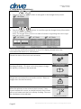
How to Lift the Patient
1. Instruct the patient to do the following:
• Hold onto the vertical or horizontal handgrips which even is more comfortable
on both sides of the lift.
• Lean back into the sling.
2. Make sure of the following:
• Patient's knees are secure against the knee pad.
• Patient's feet are positioned on the footplate.
• The bottom edge of the sling is positioned on the lower back. Sling is at the base
of the patient's spine.
• The patient's arms are outside of the sling.
• The rear casters are unlocked.
• Make sure the legs are in the maximum open position.
3. If transferring from a wheelchair - Lock the wheel locks of the wheelchair.
4. Press the (M1) UP button to raise the patient above the surface (bed, wheelchair
or commode) being transferred from. The patient should be elevated just high
enough to clear the surface with their weight fully supported by the lift.
How to move the Patient
1. Using the push handle, move the lift away from the surface.
2. SLOWLY, move the patient to the desired surface.
How to transfer the Patient to the desired surface
1. Have the wheelchair, bed or commode in ready:
• If transfer the patient to a wheelchair, move the wheelchair into position, lock
the wheels of the wheelchair, position the patient over the wheelchair
• If transfer the patient to a bed, position the patient as far over the bed as
possible
• If transfer the patient to a commode, position the patient over the commode.
2. Press the (M1) DOWN button and lower the patient onto the desired surface.
3. Lock the rear swivel casters of lift.
4. Unhook the sling from all attachment points on the lift.
5. Instruct the patient to lift their feet off of the footplate.
6. Remove the sling from around the patient.
7. Pull the lift away from the wheelchair, bed or commode.
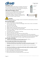
Emergency Stop
The red Emergency Stop Button is located on the top of
the control box and is activated by pressing in. This will
cut all power to the lift and only be reset by twisting the
button counter clockwise and releasing.
Mechanical Emergency Down
In the case of a complete electrical failure, the
electrical actuator is fitted with a mechanical
lowering red device on top of actuator.
It is twisted by hand to activate lowering. A slow
decent will commence. Repeat this process until
the patient has been safely lowered.
Mechanical lowering device
Page is loading ...
Page is loading ...
Page is loading ...
Page is loading ...
Page is loading ...
Page is loading ...
Page is loading ...
Page is loading ...
Page is loading ...
Page is loading ...
Page is loading ...
Page is loading ...
Page is loading ...
Page is loading ...
Page is loading ...
-
 1
1
-
 2
2
-
 3
3
-
 4
4
-
 5
5
-
 6
6
-
 7
7
-
 8
8
-
 9
9
-
 10
10
-
 11
11
-
 12
12
-
 13
13
-
 14
14
-
 15
15
-
 16
16
-
 17
17
-
 18
18
-
 19
19
-
 20
20
-
 21
21
-
 22
22
-
 23
23
-
 24
24
-
 25
25
-
 26
26
-
 27
27
-
 28
28
-
 29
29
-
 30
30
-
 31
31
-
 32
32
-
 33
33
-
 34
34
-
 35
35


Drive Medical STSP450 Owner's manual
- Type
- Owner's manual
- This manual is also suitable for
Ask a question and I''ll find the answer in the document
Finding information in a document is now easier with AI
Related papers
-
Drive Medical 13012 Owner's manual
-
-
-
-
-
-
-
-
Drive Medical Pinniped Pediatric Commode Owner's manual
-
Other documents
-
Invacare RPS350-2 User manual
-
-
 MILWAUKEE'S Milwaukee 2457-20 M12 Cordless 3/8" Sub-Compact 35 ft-Lbs 250 RPM Ratchet click here.
-
-
-
 Proactive Medical 30100 User manual
-
-
 SPAN F500S Owner's manual
-
-


