Shimano SG-3C41 User manual

Type
User manual

This manual is also suitable for

©Aug. 2020 by Shimano Inc. ITP
Ver.1.1
SERVICE MANUAL
SG-3R40
SG-3C41
SG-3D55
1
Introduction of INTER-3 / Explain the technologies
………………………
2
Dealer's Manual
………………………………………………………………………………………………………………………
3
  
SG-3R40, SG-3C41, SG-3D55
    
• INSTALLATION
   
• MAINTENANCE
Troubleshooting
………………………………………………………………………………………………………………………
32
Disassembly & Assembly
………………………………………………………………………………………………
34
  
Tools
  
Disassembly of the Inter-3 hub (Roller Brake Spec.)
  
Assembly of the Inter-3 hub (Roller Brake Spec.)
Service Parts
…………………………………………………………………………………………………………………………………
46
Interchangeability
…………………………………………………………………………………………………………………
48
Hub dimensions
…………………………………………………………………………………………………………………………
50
EV / Spare Parts List
………………………………………………………………………………………………………………
52
CONTENTS
2
Return to index page
SG-3R40
INTER-3 Rear Hub (3-speed)
• Internal Gear Shifting
» Gear shifting action is independent of pedaling.
You can shift gears anytime, while standing still,
pedaling or coasting
• Gear Change Support
• Weight: 885g
• Color options: Black, Silver, White
SG-3C41
INTER-3 Rear Hub (3-speed)
• Internal geared hub for Coaster Brake version
• Integral Coaster Brake
• Gear Change Support Mechanism
• Weight: 1,120g
SG-3D55
INTER-3 Rear Hub (3-speed)
• Internal geared hub for Disc Brake version
• Gear Change Support Mechanism
• Aluminum hub shell
• CENTER LOCK Rotor mount system
• Weight: 945g
• Color options: Black, Silver
Surface Treatment
• The Standard version is designed to use under normal climate conditions.
• The DX version features a clear coated finish and/or stainless steel material.
This finish is offering an advanced protection against corrosion and is therefore recommended to use under more severe climate
conditions.
Gear Change Support
TECHNOLOGIES
SHIMANO gear change support mechanism utilizes some portion of pedaling force at down shifting. The result is a quick and precise
downshift with very light feeling.
Coaster Brake
The SHIMANO NEXUS coaster brake is operated by pedaling backward in a similar way as ordinary types. Its uniqueness is that braking
power transmitted to the wheel directly for the SHIMANO NEXUS internal coaster brake is independent of the gear shifting mechanism
built into the hub. Also it always generates the same braking force regardless of gear position to actualize comfortable and reliable
riding. It actualizes the braking force to meet the ISO 4210 standard.
Hub shell
Sprocket
Brake shoe
Brake roller Braking cam
Actuator
Equal braking force in each gear
What is the difference between the Standard and the DX version?
3
Return to index page
Dealer's Manual
SG-3R40
SG-3C41
SG-3D55
4
https://si.shimano.com/DM/SG0005
Return to index page
Click here for the latest Dealer's Manual
4
INSTALLATION
Installation of the lever
Installation of the REVOSHIFT lever
1
(B)(A)
(C)
(z)
Install the brake lever (B).
(z)
Use Φ22.2 mm handlebars.
(A)
Brake lever band
(B)
Brake lever
(C)
Handlebar
Tightening torque
6 - 8 N·m
TECH TIPS
Use a brake lever with a band having a
thickness of 4.3 mm or lower to prevent the
brake lever and REVOSHIFT lever from
interfering with each other.
2
(A)
Install the REVOSHIFT lever (A).
(A)
REVOSHIFT lever
WARNING
When securing the brake arm to the frame, be sure to use an arm clip that matches the size of the chainstay, and securely tighten it with the clip bolt and
clip nut to the specified tightening torque. Use a lock nut with a nylon insert (self-locking nut) for the clip nut. It is recommended that Shimano made clip
bolts, clip nuts, and arm clips be used. Use an arm clip that matches the chainstay.
If the clip nut comes off the brake arm, or if the clip bolt or arm clip becomes damaged, the brake arm may rotate on the chainstay and cause the
handlebars to jerk suddenly, or the bicycle wheel may lock and the bicycle fall over, causing serious injury.
5
https://si.shimano.com/DM/SG0005
Return to index page
Click here for the latest Dealer's Manual
5
3
(A)
(B)
Install the half grip (A).
Leave a gap (B) of 0.5 mm between the
REVOSHIFT lever and the half grip.
(A)
Half grip
(B)
Gap between the REVOSHIFT lever
and the half grip
4
(A)
Tighten the REVOSHIFT lever.
(A)
Fixing bolt
Tightening torque
2 - 2.5 N·m
2 - 4 N·m
Installation of the shifting lever (RAPIDFIRE PLUS)
(A)
Secure the shifting lever using the clamp
screw (A).
(A)
Clamp screw
Tightening torque
5
N·m
6
https://si.shimano.com/DM/SG0005
Return to index page
Click here for the latest Dealer's Manual
6
Installation of the bell crank type hub
Installation of the shifting cable
1
REVOSHIFT lever
(A)
RAPIDFIRE PLUS
(A)
Insert the outer casing into the outer
casing holder (A).
(A)
Outer casing holder
2
(A)
(B)
(C)
(D)
Fit the inner cable into the link (B) in the
bell crank.
Loosen the inner cable mounting nut (D)
on the bell crank.
Pass the inner cable through the cable
adjustment barrel (A) along the groove
in the link and between the link and
inner cable mounting plate (C).
(A)
Cable adjustment barrel
(B)
Link
(C)
Inner cable mounting plate
(D)
Inner cable mounting nut
NOTICE
Make sure to pass the inner cable through the
groove in the link.
3
REVOSHIFT lever
RAPIDFIRE PLUS
Set the shifting lever to 2.
7
https://si.shimano.com/DM/SG0005
Return to index page
Click here for the latest Dealer's Manual
7
4
(y) (y)
(z)
With the inner cable kept tight, tighten
the inner cable mounting nut while
positioning the end of the link between
the two white lines on the window.
(y)
White lines
(z)
Position the end of the link
between the white lines.
5
(z)
After tightening the inner cable
mounting nut, cut off the excess length
of inner cable.
(z)
Within 4 mm
8
https://si.shimano.com/DM/SG0005
Return to index page
Click here for the latest Dealer's Manual
8
6
(A)
(B)
Tighten the bottom cover (B) with the
bottom cover fixing screw (A).
(A)
Bottom cover fixing screw
(B)
Bottom cover
Tightening torque
0.4 - 0.7 N·m
(SM-BC03)
0.35 - 0.55 N·m
(SM-BC04/SM-BC06)
9
https://si.shimano.com/DM/SG0005
Return to index page
Click here for the latest Dealer's Manual
9
Installation of the sprocket to the hub (SM-GEAR)
(z)
(A)
(B)
(C)
(D)
(E)
Place the right-hand waterproof cap B
(C) onto the driver (D) on the right side
of the hub body.
Next, install the sprocket (B) and secure
it in place with the snap ring (A).
(z)
Note the direction
(A)
Snap ring
(B)
Sprocket
(C)
Right-hand waterproof cap B
(D)
Driver
(E)
Right-hand waterproof cap A
Installation of the sprocket to the hub (CS-S500 sprocket with chain guard)
1
(A)
(B)
(C)
(D)
(z)
(B)
(A)
Install the chain guard (B) to the
right-hand waterproof cap A (D) of the
hub body, and then install the right-
hand waterproof cap B (A) to the driver
(C).
(z)
Note the direction
(A)
Right-hand waterproof cap B
(B)
Chain guard
(C)
Driver
(D)
Right-hand waterproof cap A
NOTICE
Do not use an inward assembling sprocket
with 16T or less, otherwise the right-hand
waterproof cap A will come into contact with
the sprocket.
10
https://si.shimano.com/DM/SG0005
Return to index page
Click here for the latest Dealer's Manual
10
2
(D)
(C)
(B)
(A)
Install the CS-S500 sprocket (C) to the
driver (D) on the right side of the hub
body with the guard plate (B) facing
outward, and secure it in place with the
snap ring (A).
(A)
Snap ring
(B)
Guard plate
(C)
CS-S500 Sprocket
(D)
Driver
11
https://si.shimano.com/DM/SG0005
Return to index page
Click here for the latest Dealer's Manual
11
Installation of the hub to the frame (for disc brakes)
1
(A) (B) (C)
Install the disc brake rotor (A) to the
hub.
(A)
Disc brake rotor
(B)
Disc brake rotor mounting ring
(C)
TL-LR10
Tightening torque
40 N·m
< When not using the chain tensioner >
2
(A)
(B)
Mount the chain on the sprocket, and
then set the hub axle (B) into the
dropout (A).
(A)
Dropout
(B)
Hub axle
< When using the chain tensioner >
2
(A)
Mount the chain on the sprocket, and
then set the hub axle into the dropout.
When using the chain tensioner (A), be
sure to read the attached instruction
manual for the CT-S500 chain tensioner.
(A)
Chain tensioner
12
https://si.shimano.com/DM/SG0005
Return to index page
Click here for the latest Dealer's Manual
12
3
(A)
(z)
Place the non-turn washer (A) onto the
left side of the hub axle from the outer
side.
At this time, turn the hub axle and install
the non-turn washer so that the
protrusion of the washer fits into the
groove in the dropout.
(z)
The protrusion should be on the
dropout side.
Install the non-turn washer so
that the protrusion fits securely in
the dropout groove at the front
and back sides of the hub axle.
(A)
Non-turn washer
NOTICE
Use a non-turn washer that matches the
shape of the dropout.
Dropout
Non-turn washer (for left side use)
Mark / Color Size
Standard
2 / Yellow
ϴ ≤ 20°
ϴ ≤ 38°
Reversed ϴ = 0°
Reversed (full chain
case)
ϴ = 0°
Vertical 8L / Green ϴ = 60° - 90°
Mark
13
https://si.shimano.com/DM/SG0005
Return to index page
Click here for the latest Dealer's Manual
13
4
(A)
(B)
Take up the slack in the chain and secure
the wheel to the frame, using a 3.2 mm
washer (A) and a 9 mm hub nut (B) on
the right side and a cap nut on the left
side of the hub axle.
(A)
Washer (3.2 mm)
(B)
Hub nut (9 mm)
Tightening torque
30 - 45 N·m
NOTICE
Make sure that the hub axle on the right side
protrudes about 8 to 13 mm from the end
face of the hub nut.
Dropout
Hub axle
Hub nut
(9 mm)
W
asher (3.2 mm)
Sprocket
8 - 13 mm
Total width of the dropout and
chain tensioner: 6.5 to 10 mm
When installing the hub to the frame, the
chain guard may come off, so check that the
chain guard is securely installed so that it will
not come off.
If installation is incomplete, noise may be
generated.
Chain guard
14
https://si.shimano.com/DM/SG0005
Return to index page
Click here for the latest Dealer's Manual
14
Installation of the hub to the frame (for roller brakes)
1
(A) (B)
(z)
Engage the splines on the hub body (B)
with the splines on the inter-M brake
(A), and then provisionally tighten the
brake unit fixing nut.
(z)
Align the splines
(A)
Inter-M brake
(B)
Hub body
NOTICE
Fully tightening the brake unit fixing nut may
make the wheel difficult to turn when the
arm clip is attached later.
Refer to the instruction manual for the
inter-M brake for details on installing the
inter-M brake.
2
(A)
(B)
Mount the chain on the sprocket, and
then set the hub axle (A) into the
dropout (B).
(A)
Hub axle
(B)
Dropout
3
(A) (z)
Place the non-turn washer (A) onto the
left side of the hub axle from the outer
side.
At this time, turn the hub axle and install
the non-turn washer so that the
protrusion of the washer fits into the
groove in the dropout.
(z)
The protrusion should be on the
dropout side.
Install the non-turn washer so
that the protrusion fits securely in
the dropout groove at the front
and back sides of the hub axle.
(A)
Non-turn washer (gold)
NOTICE
When installing a stand to the hub axle,
place the non-turn washer onto the stand
from the outer side so that the protrusion
fits into the groove in the stand.
When installing a part such as a mudguard
stay to the hub axle, place it onto the outer
side of the non-turn washer.
Non-turn washer
Mudguard stay
Carrier stay
Stand
15
https://si.shimano.com/DM/SG0005
Return to index page
Click here for the latest Dealer's Manual
15
4
(C)
(D)
(A) (B)
Install the brake arm (C) of the inter-M
brake to the chainstay (A) using the arm
clip (B) and temporarily tighten the clip
bolt and clip nut loosely.
Then, tighten the brake unit fixing nut
(D).
(A)
Chainstay
(B)
Arm clip
(C)
Brake arm
(D)
Brake unit fixing nut
Tightening torque
20 - 25 N·m
NOTICE
If it is impossible to temporarily attach the
brake arm to the chainstay due to
misalignment of the brake arm as shown in
the illustration, loosen the brake unit fixing
nut and turn the brake arm before
temporarily attaching it to the chainstay.
Then, tighten the brake unit fixing nut.
< For a 170.3 mm long axle >
5
(A)
Take up the slack in the chain and secure
the wheel to the frame with the flange
nut (A).
(A)
Flange nut
Tightening torque
30 - 45 N·m
NOTICE
Make sure that the hub axle on the right side
protrudes 8 to 13 mm from the end face of
the flange nut.
8 - 13 mm
Total width of the dropout and chain
tensioner: 4 to 7.5 mm
Sprocket
Hub axle
Flange nut
(11 mm)
Dropout
16
https://si.shimano.com/DM/SG0005
Return to index page
Click here for the latest Dealer's Manual
16
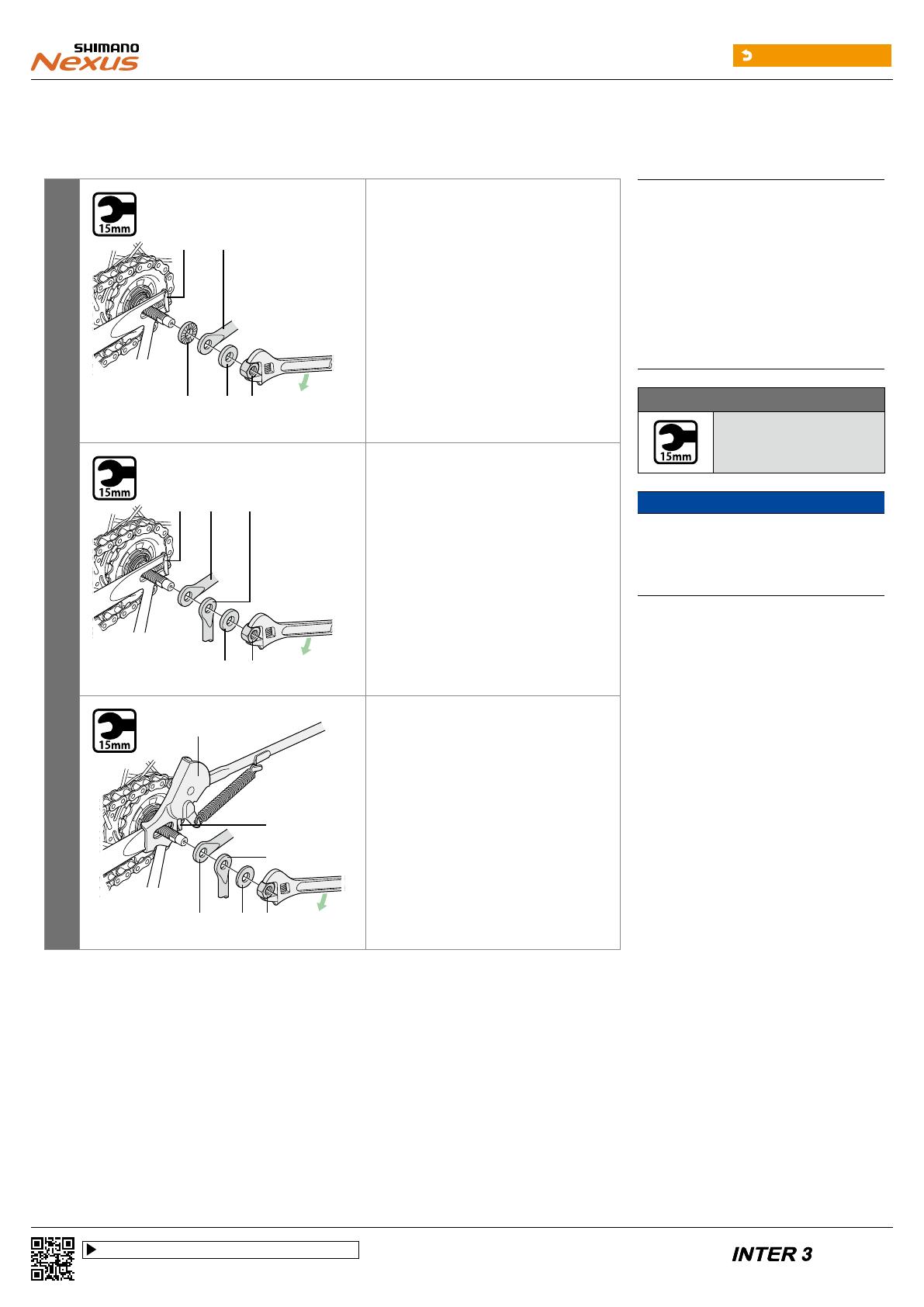
< For a 189.4 mm long axle >
5
(C) (C) (D)
(A) (B)
If the total width of the dropout and
other parts such the stand and
mudguard stay (B), on the right side of
the hub axle, is 8.5 to 11.5 mm
Secure the right side of the hub axle
with two 3.2 mm washers (C) and a 9 mm
hub nut (D).
Secure the left side of the hub axle with
a 3.2 mm washer and a 9 mm hub nut.
Example: Mount the parts in the order
shown in the illustration.
(A)
Chain tensioner
(B)
Mudguard stay
(C)
Washer (3.2 mm)
(D)
Hub nut (9 mm)
(E)
Carrier stay
(F)
Stand
(G)
Washer (2 mm)
(H)
Hub nut (7 mm)
Tightening torque
30 - 45 N·m
NOTICE
In any of the cases described in this step,
make sure that the hub axle on the right side
protrudes 8 to 13 mm from the end face of
the hub nut.
(C) (D)
(A) (B) (E)
If the total width of the dropout and
other parts such the stand and
mudguard stay, on the right side of the
hub axle, is 11.5 to 14.5 mm
Secure the both side of the hub axle with
a 3.2 mm washer (C) and a 9 mm hub nut
(D).
Example: Mount the parts in the order
shown in the illustration.
(G)(B) (H)
(F)
(E)
(A)
If the total width of the dropout and
other parts such the stand (F) and
mudguard stay, on the right side of the
hub axle, is 14.5 to 17 mm
Secure both sides of the hub axle with a
2 mm washer (G) and a 7 mm hub nut
(H).
Example: Mount the parts in the order
shown in the illustration.
17
https://si.shimano.com/DM/SG0005
Return to index page
Click here for the latest Dealer's Manual
17
6
(C)
(B)
(z)
(A)
Fix the brake arm (C) of the inter-M
brake securely to the chainstay (A) with
the arm clip (B).
(z)
If excessive force is applied to the
brake arm, the wheel will become
difficult to turn.
Be careful not to apply excessive
force when installing.
(A)
Chainstay
(B)
Arm clip
(C)
Brake arm
Tightening torque
2 - 3 N·m
NOTICE
When installing the arm clip, securely
tighten the clip bolt while holding the clip
nut with a 10 mm spanner.
After installing the arm clip, check that the
clip bolt protrudes about 4 mm from the
end face of the clip nut.
About 4 mm
Arm clip
Clip bolt
(M6 × 16 mm)
Brake armClip nut
18
https://si.shimano.com/DM/SG0005
Return to index page
Click here for the latest Dealer's Manual
18
Installing the brake cable
1
(z)
( C)
(A) (B)
Place the cable adjustment barrel (A) so
that it is 15 – 17 mm from the end of the
brake arm (B), and then pass the inner
cable through the cable adjustment
barrel of the brake arm and then
through the hole in the inner cable
fixing bolt (C).
(z)
Should be 15 – 17 mm
(A)
Cable adjustment barrel
(B)
Brake arm
(C)
Hole in the inner cable fixing bolt
2
(z)
(A)
Check that both ends of the outer casing
are securely inserted into the cable
adjustment barrels (A) of both the brake
lever and brake arm.
(z)
Both ends of the outer casing
should be securely inserted.
(A)
Cable adjustment barrel
3
(z)
(A)
(C)
(B)
Pull the link (A) back until it stops. Then,
while pulling the inner cable (C) to apply
the full amount of tension to the cable,
tighten the inner cable fixing nut (B).
(A)
Link
(B)
Inner cable fixing nut
(C)
Inner cable
Tightening torque
6 - 8 N·m
NOTICE
Set the inner cable so that it passes below the
link as shown in illustration (z).
19
https://si.shimano.com/DM/SG0005
Return to index page
Click here for the latest Dealer's Manual
19
Adjusting the brake cable
1
(z)
After checking that the wheel does not
easily turn while the brake cable is being
pulled, depress the brake lever about 10
times as far as the grip in order to run in
the brake cable.
(z)
Depress about 10 times
NOTICE
If the brake cable is not run in, it will need to
be adjusted again after only a short period of
use.
2
(z)
(A)
Turn the cable adjustment barrel (A) so
that there is about 15 mm of gap (z) in
the brake lever.
*
The amount of brake lever gap is the
distance from the position where the
brake lever is not operated to the
position where a force is felt suddenly
when the brake lever is pulled.
(A)
Cable adjustment barrel
3
(A)
After depressing the brake lever to check
the braking performance, secure the
cable adjustment barrel with the cable
adjusting nut (A).
(A)
Cable adjusting nut
Tightening torque
1 - 2 N·m
  • Page 1 1
  • Page 2 2
  • Page 3 3
  • Page 4 4
  • Page 5 5
  • Page 6 6
  • Page 7 7
  • Page 8 8
  • Page 9 9
  • Page 10 10
  • Page 11 11
  • Page 12 12
  • Page 13 13
  • Page 14 14
  • Page 15 15
  • Page 16 16
  • Page 17 17
  • Page 18 18
  • Page 19 19
  • Page 20 20
  • Page 21 21
  • Page 22 22
  • Page 23 23
  • Page 24 24
  • Page 25 25
  • Page 26 26
  • Page 27 27
  • Page 28 28
  • Page 29 29
  • Page 30 30
  • Page 31 31
  • Page 32 32
  • Page 33 33
  • Page 34 34
  • Page 35 35
  • Page 36 36
  • Page 37 37
  • Page 38 38
  • Page 39 39
  • Page 40 40
  • Page 41 41
  • Page 42 42
  • Page 43 43
  • Page 44 44
  • Page 45 45
  • Page 46 46
  • Page 47 47
  • Page 48 48
  • Page 49 49
  • Page 50 50
  • Page 51 51
  • Page 52 52
  • Page 53 53
  • Page 54 54
  • Page 55 55
  • Page 56 56
  • Page 57 57
  • Page 58 58

Shimano SG-3C41 User manual

Type
User manual
This manual is also suitable for

Ask a question and I''ll find the answer in the document

Finding information in a document is now easier with AI