LGE Internal Use Only
-18-
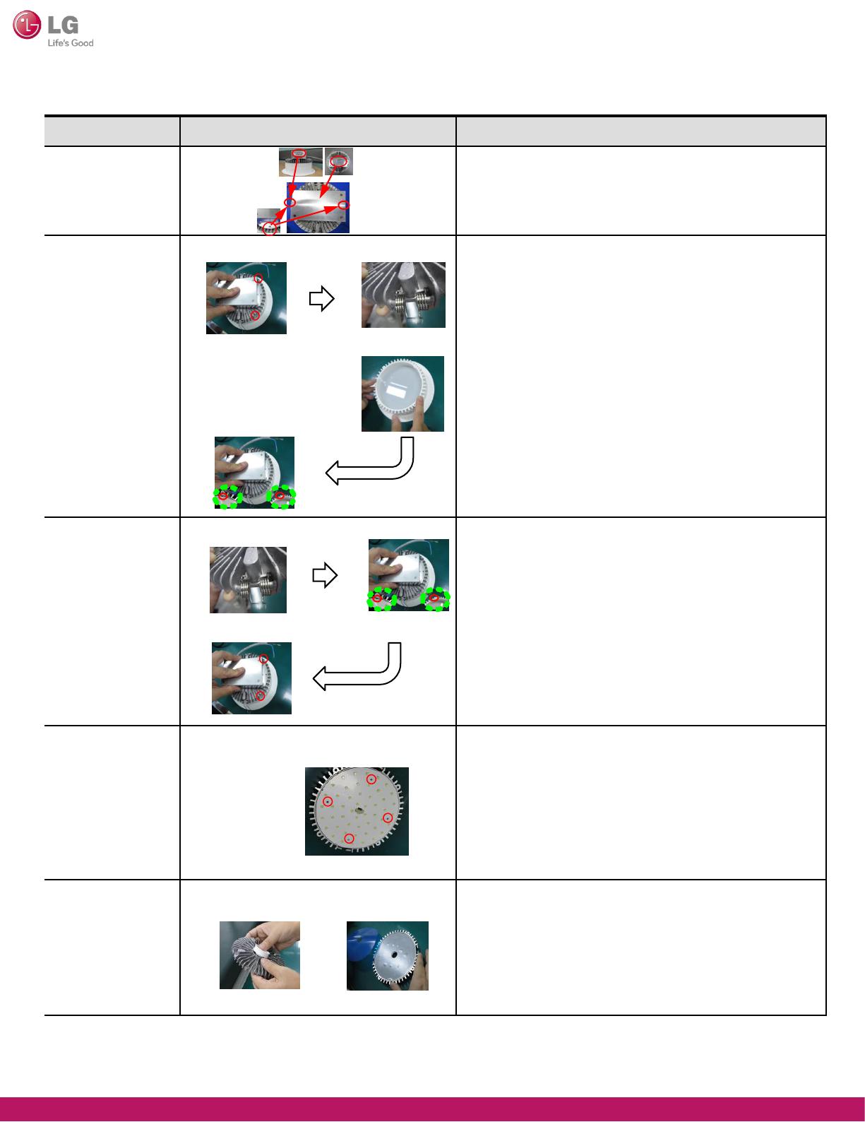
Part replacement method
Part Picture Direction
SMPS
① Use electric or manual driver to loosen 2 M3*6
machine screws assembled on SMPS and heat sink.
② Replace the SMPS.
Case, Body
Cover, Optic
Cover, Guide
① Use the electric driver to loosen the M3*30
tapping screw assembled on the heat sink
and main unit (Case body, cover guide).
(M3*30 4 screws)
② Disassemble the heat sink from the case body.
③ Disassemble the case body from the cover guide.
④ Disassemble the cover optic from the cover guide.
⑤ Remove the part to replace and replace it with a new part.
⑥ Place the cover optic on the cover guide.
⑦ Place the case body on the cover guide.
⑧ Align the case body groove to that of the heat sink
and place the heat sink on top of the case body.
⑨ Use the electric or manual driver to tighten the M3*30
tapping screw to assemble the heat sink and main unit
(Case body, cover guide). (M3*30 4 screws)
Spring
① Use the electric driver to loosen the M3*30 tapping screw
assembled on the heat sink and main unit
(Case body, cover guide). (M3*30 3 screws)
② Disassemble the heat sink from the case body.
③ Separate the heat sink and the spring, and replace
the spring. (2 springs)
④ Align the case body groove to that of the heat sink
and place the heat sink on top of the case body.
⑤ Use the electric or manual driver to tighten the M3*30
tapping screw to assemble the heat sink and main unit
(Case body, cover guide). (M3*30 4 screws)
LED Assembly
① Use the electric driver to loosen the M3*30 tapping screw
assembled on the heat sink and main unit
(Case body, cover guide). (M3*30 4 screws)
② Disassemble the heat sink from the case body
③ Disassemble the LED PCB from the heat sink.
(M2*4 4 locations)
④ Replace the LED PCB with a new one. If the insulator is
damaged, replace it as well.
Base Assembly,
Rear
① Use the electric driver to loosen the M3*30 tapping screw
assembled on the heat sink and main unit
(Case body, cover guide). (M3*30 4 screws)
② Disassemble the heat sink from the case body.
③ Disassemble the LED PCB from the heat sink.
(M2*4 4 locations)
④ Replace heat sink, bush or insulator with a new part.
①
①
②
③,④
⑥,⑦,⑧,⑨
①,②,③
④
⑤
①,②,③
①,②,③,④


