Homelite ut41110 Owner's manual
- Category
- Grass trimmers
- Type
- Owner's manual

OPERATOR’S MANUAL
MANUEL D’UTILISATION
MANUAL DEL OPERADOR
UT41110 / String Trimmer
Tondeuse à fouet
Recortadora de hilo
SAVE THIS MANUAL FOR FUTURE REFERENCE
Your string trimmer has been engineered and manufactured to Homelite’s high standard for dependability, ease of operation,
and operator safety. When properly cared for, it will give you years of rugged, trouble-free performance.
WARNING: To reduce the risk of injury, the user must read and understand the operator’s manual before us-
ing this product.
Thank you for buying a Homelite product.
Cette tondeuse à fouet a été conçue et fabriquée conformément
aux strictes normes de fiabilité, simplicité d’emploi et sécurité
d’utilisation de Homelite. Correctement entretenue, elle vous
donnera des années de fonctionnement robuste et sans
problème.
AVERTISSEMENT : Pour réduire les risques de
blessures, l’utilisateur doit lire et veiller à bien comprendre le
manuel d’utilisation avant d’employer ce produit.
Merci d’avoir acheté un produit Homelite.
Su recortadora de hilo ha sido diseñada y fabricada de
conformidad con las estrictas normas de Homelite para brindar
fiabilidad, facilidad de uso y seguridad para el operador. Con el
debido cuidado, le brindará muchos años de sólido y eficiente
funcionamiento.
ADVERTENCIA: Para reducir el riesgo de lesiones,
el usuario debe leer y comprender el manual del operador antes
de usar este producto.
Le agradecemos la compra de un producto Homelite.
CONSERVER CE MANUEL POUR
FUTURE RÉFÉRENCE
GUARDE ESTE MANUAL PARA
FUTURAS CONSULTAS

Page 2
Introduction ...................................................................................................................................................................... 2
Introduction / Introducción
Important Safety Instructions ........................................................................................................................................3-4
Instructions importantes concernant la sécurité / instrucciones de seguridad importantes
Symbols .........................................................................................................................................................................5-6
Symboles / Símbolos
Electrical ........................................................................................................................................................................... 7
Caractéristiques électriques / Aspectos eléctricos
Features ............................................................................................................................................................................ 8
Caractéristiques / Características
Tools Needed .................................................................................................................................................................... 8
Outils nécessaires / herramientas necesarias
Assembly .......................................................................................................................................................................... 9
Assemblage / Armado
Operation ...................................................................................................................................................................10-12
Utilisation / Funcionamiento
Maintenance ................................................................................................................................................................... 13
Entretien / Mantenimiento
Troubleshooting .............................................................................................................................................................. 14
Dépannage / Corrección de problemas
Warranty ......................................................................................................................................................................... 15
Garantie / Garantía
Parts Ordering and Service ...............................................................................................................................Back Page
Commande de pièces et réparation / Pedidos de piezas y servicio ......................................................... Page arrière / Pág. posterior
TABLE OF CONTENTS
TABLE DES MATIÈRES / ÍNDICE DE CONTENIDO
This product has many features for making its use more pleasant and enjoyable. Safety, performance, and dependability
have been given top priority in the design of this product making it easy to maintain and operate.
* * *
Ce produit offre de nombreuses fonctions destinées à rendre son utilisation plus plaisante et satisfaisante. Lors de la
conception de ce produit, l’accent a été mis sur la sécurité, les performances et la fiabilité, afin d’en faire un outil facile à
utiliser et à entretenir.
* * *
Este producto ofrece numerosas características para hacer más agradable y placentero su uso. En el diseño de este producto
se ha conferido prioridad a la seguridad, el desempeño y la fiabilidad, por lo cual se facilita su manejo y mantenimiento.
INTRODUCTION
INTRODUCTION / INTRODUCCIóN

Page 3 — English
IMPORTANT SAFETY INSTRUCTIONS
WARNING:
Read and understand all instructions. Failure to follow
all instructions listed below may result in electric shock,
fire and/or serious personal injury.
READ ALL INSTRUCTIONS
For safe operation, read and understand all instructions
before using this product. Follow all safety instructions.
Failure to follow all safety instructions listed below, can
result in serious personal injury.
Do not allow children or untrained individuals to use this
unit.
Check the work area before each use. Remove all objects
such as rocks, broken glass, nails, wire, or string which
can be thrown or become entangled in the machine.
Wear eye protection which is marked to comply with ANSI
Z87.1 when operating this product.
Use Safety Glasses – Always use face or dust mask if
operation is dusty.
Always wear safety glasses with side shields.
Everyday glasses have only impact resistant lenses. They
are NOT safety glasses. Following this rule will reduce the
risk of eye injury. Use face mask if operation is dusty.
Dress Properly – Use rubber gloves and substantial foot-
wear is recommended when working outdoors.
Wear heavy, long pants, boots, and gloves. Do not wear
loose fitting clothing, short pants, or go barefoot. Do not
wear jewelry of any kind.
Secure long hair above shoulder level to prevent entan-
glement in moving parts.
Keep children away - Keep all bystanders, children, and
pets at least 50 ft. away.
Stay alert - Do not operate this unit when you are tired, ill,
or under the influence of alcohol, drugs, or medication.
Do not operate in poor lighting.
Keep all parts of your body away from any moving part.
Do not operate power tools in explosive atmospheres,
such as in the presence of flammable liquids, gases, or
dust. Power tools create sparks which may ignite the dust
or fumes.
To reduce the risk of electric shock, this tool has a po-
larized plug (one blade is wider than the other) and will
require the use of a polarized extension cord. The plug
will fit into a polarized extension cord only one way. If the
plug does not fit fully into the extension cord, reverse the
plug. If the plug still does not fit, obtain a correct polarized
extension cord. A polarized extension cord will require
the use of a polarized wall outlet. This plug will fit into the
polarized wall outlet only one way. If the plug does not fit
fully into the wall outlet, reverse the plug. If the plug still
does not fit, contact a qualified electrician to install the
proper wall outlet. Do not change the equipment plug,
extension cord receptacle, or extension cord plug in any
way.
Avoid body contact with grounded surfaces such as
pipes,
radiators, ranges, and refrigerators. There is an increased
risk of electric shock if your body is grounded.
Avoid Dangerous Environments - Don’t expose power
tools to rain or wet conditions. Water entering a power
tool will increase the risk of electric shock.
Warning – To reduce the risk of electric shock -
Use
outdoor extension cords marked W-A, W,
SW-A, SOW-A,
STW-A, STOW-A, SJW-A, SJTW-A, or SJTOW-A.
These
cords are rated for outdoor use and reduce the risk of elec-
tric shock.
Ground Fault Circuit Interrupter (GFCI) protection should
be provided on the circuit(s) or outlet(s) to be used for the
gardening appliance.
Receptacles are available having
built-in GFCI protection and may be used for this measure
of safety.
Use Right Appliance - Do not force tool. Use the correct
tool for your application. The correct tool will do the job
better and safer at the rate for which it is designed.
Do not operate the equipment while barefoot or when
wearing sandals or similar lightweight footwear. Wear
protective footwear that will protect your feet and improve
your footing on slippery surfaces.
Do not overreach. Keep firm footing and balance. Over-
reaching can result in loss of balance.
Avoid Accidental Start – Do not carry plugged in appliance
with finger on trigger. Be sure the switch trigger is not en-
gaged before plugging in.
Do not use tool if switch trigger does not turn it on or off.
Any tool that cannot be controlled with the switch trigger
is dangerous and must be repaired.
Disconnect appliance from power source before storing,
servicing, changing accessories such as cutting line. Such
preventive safety measures reduce the risk of starting the
tool accidentally.
Use only identical manufacturer’s replacement parts and
accessories. Use of any other parts may create a hazard
or cause product damage.

Page 4 — English
Maintain appliance with care - Replace string head if
cracked, chipped, or damaged in any way. Be sure the
string head is properly installed and securely fastened.
Failure to do so can cause serious injury.
Make sure all guards, straps, deflectors and handles are
properly and securely attached.
Use only the manufacturer’s replacement string in the
cutting head. Do not use any other cutting attachment,
for example, metal wire, rope, or the like. To install any
other brand of cutting head to this string trimmer can
result in serious personal injury.
Never operate unit without the grass deflector in place
and in good condition.
Check damaged parts. Before further use of the tool, a
guard or other part that is damaged should be carefully
checked to determine that it will operate properly and
perform its intended function. Check for alignment of
moving parts, binding of moving parts, breakage of parts,
mounting and any other conditions that may affect its
operation. A guard or other part that is damaged must
be properly repaired or replaced by an authorized service
center to avoid risk of personal injury.
Maintain a firm grip on both handles while trimming. Keep
string head below waist level. Never cut with the string
head located over 30 in. or more above the ground.
Store idle appliances - When not in use, string trimmer
should be stored indoors in a dry, locked place out of the
reach of children.
Make sure your extension cord is in good condition.
When using an extension cord, be sure to use one heavy
enough to carry the current your product will draw. A wire
gauge size (A.W.G.) of at least 16 is recommended for an
extension cord 50 feet or less in length. A cord exceeding
100 feet is not recommended. If in doubt, use the next
heavier gauge. The smaller the gauge number, the heavier
the cord. An undersized cord will cause a drop in line
voltage resulting in loss of power and overheating.
Never use blades or flailing devices. Unit is designed for
line trimmer use only. Use of any other accessories or
attachments will increase the risk of injury.
Inspect area to be cut. Remove objects (rocks, broken
glass, nails, wire, string, etc.) which can be thrown or
become entangled in cutting head.
Keep the air vents clean and free of debris to avoid
overheating the motor. Clean after each use.
Stop the unit and disconnect the power source when not
in use. Carry the unit with the motor stopped.
Store unplugged and out of the reach of children.
Do not hang unit so that the switch trigger is
depressed.
Do not use multiple cords.
Do not abuse the cord. Never carry the unit by the
extension cord or yank extension cord to disconnect
unit.
Keep the extension cord clear of operator and obstacles
at all times. Do not expose cords to heat, oil, water, or
sharp edges.
If the power supply cord is damaged, it must be replaced
only by the manufacturer or by an authorized service
center to avoid risk.
Save these instructions. Refer to them frequently and
use them to instruct others who may use this power tool.
If you loan someone this power tool, loan them these
instructions also.
IMPORTANT SAFETY INSTRUCTIONS
WARNING:
Some dust created by power sanding, sawing, grinding, drilling, and other construction activities contains chemicals
known to cause cancer, birth defects or other reproductive harm. Some examples of these chemicals are:
• lead from lead-based paints,
• crystalline silica from bricks and cement and other masonry products, and
• arsenic and chromium from chemically-treated lumber.
Your risk from these exposures varies, depending on how often you do this type of work. To reduce your exposure to
these chemicals: work in a well ventilated area, and work with approved safety equipment, such as those dust masks
that are specially designed to filter out microscopic particles.

Page 5 — English
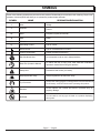
SYMBOLS
Keep Bystanders Away
To reduce the risk of injury, user must read and understand
operator’s manual before using this product.
Keep all bystanders at least 50 ft. away.
Some of the following symbols may be used on this product. Please study them and learn their meaning. Proper inter-
pretation of these symbols will allow you to operate the product better and safer.
Read The Operator’s Manual
Safety Alert
SYMBOL NAME DESIGNATION/EXPLANATION
Voltage
Current
Frequency (cycles per second)
Power
Time
Type of current
Type or a characteristic of current
Double-insulated construction
Do not expose to rain or use in damp locations.
Precautions that involve your safety.
Wet Conditions Alert
Class II Construction
Direct Current
Alternating Current
min
Minutes
W
Watt
Hz
Hertz
A
Amperes
V
Volts
Ricochet
Thrown objects can ricochet and result in personal injury or
property damage.
No Blade
Do not install or use any type of blade on a product displaying
this symbol.
Eye Protection
Always wear safety goggles or safety glasses with side shields and,
as necessary, a full face shield when operating this product.

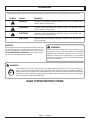
Page 6 — English
SYMBOLS
SERVICE
Servicing requires extreme care and knowledge and should
be performed only by a qualified service technician. For
service we suggest you return the product to your nearest
AUTHORIZED SERVICE CENTER for repair. When servic-
ing, use only identical replacement parts.
WARNING:
SAVE THESE INSTRUCTIONS
The following signal words and meanings are intended to explain the levels of risk associated with this product.
SYMBOL SIGNAL MEANING
DANGER: Indicates an imminently hazardous situation, which, if not avoided, will
result in death or serious injury.
WARNING: Indicates a potentially hazardous situation, which, if not avoided, could
result in death or serious injury.
CAUTION: Indicates a potentially hazardous situation, which, if not avoided, may
result in minor or moderate injury.
CAUTION: (Without Safety Alert Symbol) Indicates a situation that may result in
property damage.
WARNING:
To avoid serious personal injury, do not attempt to use
this product until you read thoroughly and understand
completely the operator’s manual. If you do not under-
stand the warnings and instructions in the operator’s
manual, do not use this product. Call Homelite customer
service for assistance.
The operation of any power tool can result in foreign objects being thrown into your eyes, which can
result in severe eye damage. Before beginning power tool operation, always wear safety goggles or
safety glasses with side shields and, when needed, a full face shield. We recommend Wide Vision Safety
Mask for use over eyeglasses or standard safety glasses with side shields. Always use eye protection
which is marked to comply with ANSI Z87.1.

Page 7 — English
EXTENSION CORDS
When using a power product at a considerable distance from
a power source, be sure to use an extension cord that has
the capacity to handle the current the product will draw. An
undersized cord will cause a drop in line voltage, resulting in
overheating and loss of power. Use the chart to determine
the minimum wire size required in an extension cord. Only
round jacketed cords listed by Underwriter’s Laboratories
(UL) should be used.
When working outdoors with a product, use an extension
cord that is designed for outside use. This type of cord is
designated with “WA” on the cord’s jacket.
Before using any extension cord, inspect it for loose or
exposed wires and cut or worn insulation.
**Ampere rating (on product data plate)
0-2.0 2.1-3.4 3.5-5.0 5.1-7.0 7.1-12.0 12.1-16.0
Cord Length Wire Size (A.W.G.)
25´ 16 16 16 16 14 14
50´ 16 16 16 14 14 12
100´ 16 16 14 12 10 —
**Used on 12 gauge - 20 amp circuit.
NOTE: AWG = American Wire Gauge
WARNING:
Keep the extension cord clear of the working area.
Position the cord so that it will not get caught on lumber,
tools, or other obstructions while you are working with
a power tool. Failure to do so can result in serious per-
sonal injury.
WARNING:
Check extension cords before each use. If damaged
replace immediately. Never use product with a damaged
cord since touching the damaged area could cause elec-
trical shock resulting in serious injury.
DOUBLE INSULATION
Double insulation is a concept in safety in electric power
tools, which eliminates the need for the usual three-
wire grounded power cord. All exposed metal parts are
isolated from the internal metal motor components with
protecting insulation. Double insulated tools do not need
to be grounded.
WARNING:
The double insulated system is intended to protect
the user from shock resulting from a break in the tool’s
internal insulation. Observe all normal safety precautions
to avoid electrical shock.
NOTE: Servicing of a product with double insulation requires
extreme care and knowledge of the system and should be
performed only by a qualified service technician. For service,
we suggest you return the tool to your nearest authorized
service center for repair. Always use original factory replace-
ment parts when servicing.
ELECTRICAL CONNECTION
This product has a precision-built electric motor. It should
be connected to a power supply that is 120 volts, AC only
(normal household current), 60 Hz. Do not operate this
product on direct current (DC). A substantial voltage drop
will cause a loss of power and the motor will overheat. If
your product does not operate when plugged into an outlet,
double-check the power supply.
GFCI
Ground Fault Circuit Interrupter (GFCI) protection should be
provided on the circuit(s) or outlet(s) to be used for the prod-
uct. Receptacles are available having built-in GFCI protection
and may be used for this measure of safety.
ELECTRICAL

Page 8 — English
FEATURES
FEATURES
Input ..............................................................................................................................................120 V, AC only, 60 Hz, 4 A
Cutting Swath .................................................................................................................................................................13 in.
Weight .........................................................................................................................................................................5.2 lbs.
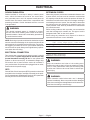
KNOW YOUR STRING TRIMMER
See Figure 1.
The safe use of this product requires an understanding of
the information on the tool and in this operator’s manual as
well as a knowledge of the project you are attempting. Before
use of this product, familiarize yourself with all operating
features and safety rules.
CORD RETAINER
A convenient cord retainer helps keep the extension cord
connection secure during string trimmer operation.
EDGER GUIDE
The easily mounted edger guide allows the string trimmer
to perform as an edger.
FEATURES
TOOLS NEEDED
PHILLIPS SCREWDRIVER
TELESCoPIng
BooM
EDgER
gUIDE
gRASS
DEFLECToR
RoTATIng REAR
HAnDLE
FRonT
HAnDLE
Fig. 1
FRONT HANDLE
The string trimmer is equipped with a front handle assembly
for ease of operation and to prevent loss of control.
GRASS DEFLECTOR
The trimmer includes a grass deflector that helps protect
from flying debris.
ROTATING REAR HANDLE
The rotating rear handle on the string trimmer can be locked
in two different positions for ease of use when edging.
TELESCOPING BOOM
The string trimmer can be adjusted to different extension
points for ease of use.
SWITCH
TRIggER
CoRD
RETAInER
The following tool (not included or drawn to scale) is needed for assembly:

Page 9 — English
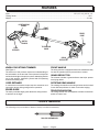
ASSEMBLY
UNPACKING
This product requires assembly.
Carefully remove the product and any accessories from
the box. Make sure that all items listed in the packing list
are included.
Inspect the product carefully to make sure no breakage
or damage occurred during shipping.
Do not discard the packing material until you have
carefully inspected and satisfactorily operated the
product.
If any parts are damaged or missing, please call
1-800-242-4672 for assistance.
PACKING LIST
Trimmer Assembly
Grass Deflector Assembly with Screw
Operator’s Manual
WARNING:
If any parts are damaged or missing do not operate this
product until the parts are replaced. Failure to heed this
warning could result in serious personal injury.
WARNING:
Do not attempt to modify this product or create acces-
sories not recommended for use with this product. Any
such alteration or modification is misuse and could result
in a hazardous condition leading to possible serious
personal injury.
WARNING:
Do not connect to power supply until assembly is com-
plete. Failure to comply could result in accidental starting
and possible serious personal injury.
Fig. 2
gRASS
DEFLECToR
SLIDE
oVER HEAD
AnD
TURn
CoUnTERCLoCKWISE
Fig. 3
SCREW
SCREW
HoLE
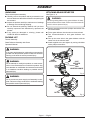
ATTACHING GRASS DEFLECTOR
See Figure 2 - 3.
WARNING:
The string cutting blade on the grass deflector is sharp.
Avoid contact with the blade. Failure to avoid contact can
result in serious personal injury.
Remove supplied screw with a phillips screwdriver from
the trimmer head.
Fit the grass deflector into the slots on trimmer head.
Turn counterclockwise to lock grass deflector into
place.
Line up the screw hole in the grass deflector with the
center hole in the trimmer head.
Install supplied screw and tighten by turning clockwise
with a phillips screwdriver.
BUTTon

Page 10 — English
OPERATION
WARNING:
Do not allow familiarity with products to make you care-
less. Remember that a careless fraction of a second is
sufficient to inflict severe injury.
WARNING:
Always wear safety goggles or safety glasses with side
shields when operating products. Failure to do so could
result in objects being thrown into your eyes resulting in
possible serious injury.
WARNING:
Do not use any attachments or accessories not recom-
mended by the manufacturer of this product. The use of
attachments or accessories not recommended can result
in serious personal injury.
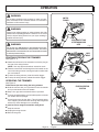
STARTING/STOPPING THE TRIMMER
See Figure 4 - 5.
Attach the outlet end of an extension cord to the plug on
the rear of the string trimmer.
NOTE: Use only approved outdoor extension cords.
Route the extension cord through the slot located on the
rear of the string trimmer housing and place underneath
the cord retainer.
To start the string trimmer, press the switch trigger.
To stop the string trimmer, release the switch trigger.
OPERATING THE TRIMMER
See Figure 6.
Follow these tips when using the string trimmer:
Hold the trimmer with your right hand on the rear handle
and your left hand on the front handle.
Keep a firm grip with both hands while in operation.
Trimmer should be held at a comfortable position with the
rear handle about hip height.
Cut tall grass from the top down. This will prevent grass
from wrapping around the shaft housing and string head
which may cause damage from overheating.
If grass becomes wrapped around the string head:
Stop the trimmer.
Unplug the string trimmer.
Remove the grass.
Fig. 4
SWITCH
TRIggER
Fig. 6
ATTACH oUTLET EnD
oF EXTEnSIon CoRD
HERE
PRoPER oPERATIng
PoSITIon
Fig. 5
CoRD
WRAP
oUTLET
EnD

Page 11 — English
2
2
1
PUSH
180°
2
1
2
180°
1
OPERATION
WARNING:
Always hold the string trimmer away from the body
keeping clearance between the body and the string
trimmer. Any contact with the string trimmer cutting head
while operating can result in serious personal injury.
ADVANCING STRINGS
NOTE: The trimmer is equipped with an auto-feed head.
Bumping the head to try to advance the string will damage
trimmer and void warranty.
With the trimmer running, release the switch trigger.
Wait two seconds, and press the switch trigger.
NOTE: The strings will extend approximately 1/4 in. with
each stop and start of the switch trigger until the strings
reach the length of the grass deflector blade.
Resume trimming.
ADVANCING THE STRINGS MANUALLY
Disconnect the string trimmer from the power supply, then
push the spool retainer button in while pulling on strings to
manually advance the strings.
CUT OFF BLADE
This trimmer is equipped with a cut-off blade on the grass
deflector. For best cutting, advance strings until they are
trimmed to length by the cut-off blade. Advance strings
whenever you hear the engine running faster than normal,
or when trimming efficiency diminishes. This will maintain
best performance and keep strings long enough to advance
properly.
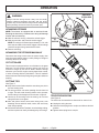
CUTTING TIPS
See Figure 7.
Keep the trimmer tilted toward the area being cut; this is
the best cutting area.
The string trimmer cuts when passing the unit from left
to right. This will avoid throwing debris at the operator.
Avoid cutting in the dangerous area shown in figure 8.
Use the tip of the string to do the cutting; do not force
string head into uncut grass.
Wire and picket fences cause extra string wear, even
breakage. Stone and brick walls, curbs, and wood may
wear strings rapidly.
Avoid trees and shrubs. Tree bark, wood moldings, siding,
and fence posts can easily be damaged by the strings.
DAngERoUS
CUTTIng AREA
BEST CUTTIng AREA
DIRECTIon
oF
RoTATIon
Fig. 7
Fig. 8
TELESCOPING BOOM
See Figure 8.
The boom can be extended or shortened for ease of use.
Unplug the string trimmer.
Unscrew telescoping boom coupler and slide to desired
position.
Tighten telescoping boom coupler.
2
2
1
PUSH
180°
2
1
2
180°
1
TELESCoPIng
BooM CoUPLER

Page 12 — English
2
180°
2
1
2
180°
2
1
OPERATION
Fig. 10
WARNING:
When servicing, use only identical replacement parts.
Use of any other parts may create a hazard or cause
product damage.
WARNING:
Always wear safety goggles or safety glasses with side
shields during product operation. If operation is dusty,
also wear a dust mask.
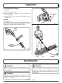
ROTATING REAR HANDLE
See Figure 9.
Unplug the string trimmer.
Pull up edging coupler and tur n handle end
counterclockwise.
Release edging boom coupler when handle has been
rotated 180°.
EDGING
See Figures 9 - 11.
The rotating handle can be used in combination with the
edger guide for edging sidewalks and walkways. To use the
edger guide, flip down from it’s stored position.
PULL UP
EDgIng CoUPLER
To RoTATE
EDgER gUIDE
Fig. 9
WARNING:
Before inspecting, cleaning, or servicing the machine,
shut off motor, wait for all moving parts to stop, and
disconnect extension cord. Failure to follow these
instructions can result in serious personal injury or prop-
erty damage.
REAR
HAnDLE
Fig. 11
MAINTENANCE

Page 13 — English
Fig. 12
SPooL
RETAInER
SLoTS
SPooL
MAINTENANCE
TABS
SPooL
Fig. 13
HoLE
WInD CLoCKWISE
SPooL
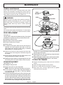
GENERAL MAINTENANCE
Avoid using solvents when cleaning plastic parts. Most
plastics are susceptible to damage from various types of
commercial solvents and may be damaged by their use. Use
clean cloths to remove dirt, dust, oil, grease, etc.
WARNING:
Do not at any time let brake fluids, gasoline, petroleum-
based products, penetrating oils, etc., come in contact
with plastic parts. Chemicals can damage, weaken or
destroy plastic which may result in serious personal
injury.
Periodically, clean all foreign material from the trimmer head
vents.
You can often make repairs described here. For other repairs,
have the trimmer serviced by an authorized service dealer.
SPOOL REPLACEMENT
See Figure 12.
Use only .065 in. diameter monofilament string. Use original
manufacturer’s replacement string for best performance.
Unplug the string trimmer.
Push in tabs on side of spool retainer.
Pull spool retainer up to remove.
Remove spool.
To install the new spool, make sure the two strings are
captured in the slots opposite each other on the new
spool. Make sure the end of each string is extended
approximately 6 in. beyond each slot.
Install the new spool so that the strings and slots align
with the eyelets in the string head. Thread the strings into
the eyelets.
Pull the strings extending from the string head so the
string releases from the slots in the spool.
Reinstall the spool retainer by depressing tabs into slots
and pushing down until spool retainer clicks into place.
STRING REPLACEMENT
See Figures 12 - 13.
Unplug the string trimmer.
Remove the spool from the string head.
NOTE: Remove any old string remaining on the spool.
Cut two pieces of string, each being approximately 9
ft. (2.7 m) long. Use only .065 in. (1.65 mm) diameter
monofilament string.
Insert the first string into the anchor hole in the upper part
of the spool. Wind the first string around the upper part of
the spool counterclockwise, as shown by the arrows on
the spool. Place string in the slot on upper spool flange,
leaving about 6 in. (152 mm) extended beyond the slot.
Do not overfill. After winding the string, there should be
at least 1/4 in. (6 mm) between the wound string and the
outside edge of the spool.
Repeat above step with second string, using the bottom
part of spool. Do not overfill.
Replace the plastic retainer, spool, and the spool retainer.
Refer to Spool Replacement earlier in this manual.
STORING THE TRIMMER
Depress telescoping boom coupler and set at shortest
setting.
Clean all foreign material from the trimmer.
Store it in a place that is inaccessible to children.
Keep away from corrosive agents such as garden
chemicals and de-icing salts.

Page 14 — English
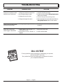
TROUBLESHOOTING
1. Lubricate with silicone spray.
2. Install more string. Refer to String Replacement
earlier in this manual.
3. Pull both strings while pressing button.
4. Remove strings from spool and rewind. Refer to
String Replacement earlier in this manual.
1. Cut tall grass from the top down to prevent
wrapping.
1. Plug in the power cord.
2. Check circuit breaker.
1. Strings are welded to themselves.
2. Not enough string on spool.
3. Strings are worn too short.
4. Strings are tangled on spool.
1. Cutting tall grass at ground level.
1. Power cord is not plugged in or
connection is loose.
2. Household circuit breaker is
tripped.
Strings will not advance when
using the Auto Feed Head:
Grass wraps around driveshaft
housing and string head
Motor fails to start when
switch trigger is depressed.
PROBLEM POSSIBLE CAUSE SOLUTION
CAL
L
1-800-242-4672
www
.homeli
te.com
CALL US FIRST
For any questions about operating or maintaining your product,
call the Homelite
®
Help Line!
Your product has been fully tested prior to shipment to ensure
your complete satisfaction.

Page 15 — English
WARRANTY
LIMITED WARRANTY STATEMENT
Homelite Consumer Products, Inc., (“Homelite”) warrants
to the original retail purchaser that this HOMELITE brand
outdoor product is free from defect in material and
workmanship and agrees to repair or replace, at Homelite’s,
discretion, any defective product free of charge within these
time periods from the date of purchase.
Two years for all models if used for personal, family, or
household use;
90 days for any unit used for other purposes, such as
rental or commercial.
This warranty extends to the original retail purchaser
only and commences on the date of the original retail
purchase.
Any part of the this product manufactured or supplied
by Homelite and found in the reasonable judgment of
Homelite to be defective in material or workmanship will
be repaired or replaced without charge for parts and labor
by a Homelite authorized service center.
The product, including any defective part, must be returned
to an authorized service dealer within the warranty period.
The expense of delivering the product to the dealer for
warranty work and the expense of returning it back to the
owner after repair or replacement will be paid by the owner.
Homelite’s responsibility in respect to claims is limited to
making the required repairs or replacements and no claim
of breach of warranty shall be cause for cancellation or
rescission of the contract of sale of any HOMELITE brand
product. Proof of purchase will be required by the dealer
to substantiate any warranty claim. All warranty work must
be performed by a Homelite authorized service center.
This warranty is limited to ninety (90) days from the date of
original retail purchase for any HOMELITE brand product
that is used for rental or commercial purposes, or any other
income-producing purpose.
This warranty does not cover any HOMELITE brand product
that has been subject to misuse, neglect, negligence, or
accident, or that has been operated in any way contrary
to the operating instructions as specified in this operator’s
manual. This warranty does not apply to any damage to
the product that is the result of improper maintenance or
to any product that has been altered or modified. The
warranty does not extend to repairs made necessary
by normal wear or by the use of parts or accessories
which are either incompatible with the HOMELITE
brand product or adversely affect its operation,
performance, or durability. In addition, this warranty does
not cover:
A. Tune-ups – Spark Plugs, Carburetor, Carburetor
Adjustments, Ignition, Filters
B. Wear items – Bump Knobs, Outer Spools, Cutting
Lines, Inner Reels, Starter Pulleys, Starter Ropes, Drive
Belts, Tines, Felt Washers, Hitch Pins, Mulching Blades,
Blower Fans, Blower and Vacuum Tubes, Vacuum Bags
and Straps, Guide Bars, Saw Chains
Homelite reserves the right to change or improve
the design of any HOMELITE brand product without
assuming any obligation to modify any product previously
manufactured.
ALL IMPLIED WARRANTIES ARE LIMITED IN DURATION
TO THE STATED WARRANTY PERIOD. ACCORDINGLY,
ANY SUCH IMPLIED WARRANTIES INCLUDING
MERCHANTABILITY, FITNESS FOR A PARTICULAR
PURPOSE, OR OTHERWISE, ARE DISCLAIMED IN
THEIR ENTIRETY AFTER THE EXPIRATION OF THE
APPROPRIATE TWO-YEAR, ONE-YEAR, OR NINETY-DAY
WARRANTY PERIOD. HOMELITE’S OBLIGATION UNDER
THIS WARRANTY IS STRICTLY AND EXCLUSIVELY
LIMITED TO THE REPAIR OR REPLACEMENT OF
DEFECTIVE PARTS AND HOMELITE DOES NOT ASSUME
OR AUTHORIZE ANYONE TO ASSUME FOR THEM ANY
OTHER OBLIGATION. SOME STATES DO NOT ALLOW
LIMITATIONS ON HOW LONG AN IMPLIED WARRANTY
LASTS, SO THE ABOVE LIMITATION MAY NOT APPLY
TO YOU. HOMELITE ASSUMES NO RESPONSIBILITY
FOR INCIDENTAL, CONSEQUENTIAL, OR OTHER
DAMAGES INCLUDING, BUT NOT LIMITED TO, EXPENSE
OF RETURNING THE PRODUCT TO AN AUTHORIZED
HOMELITE SERVICE CENTER AND EXPENSE OF
DELIVERING IT BACK TO THE OWNER, MECHANIC’S
TRAVEL TIME, TELEPHONE OR TELEGRAM CHARGES,
RENTAL OF A LIKE PRODUCT DURING THE TIME
WARRANTY SERVICE IS BEING PERFORMED, TRAVEL,
LOSS OR DAMAGE TO PERSONAL PROPERTY, LOSS
OF REVENUE, LOSS OF USE OF THE PRODUCT,
LOSS OF TIME, OR INCONVENIENCE. SOME STATES
DO NOT ALLOW THE EXCLUSION OR LIMITATION OF
INCIDENTAL OR CONSEQUENTIAL DAMAGES, SO THE
ABOVE LIMITATION OR EXCLUSION MAY NOT APPLY
TO YOU.
This warranty gives you specific legal rights, and you may
also have other rights which vary from state to state.
This warranty applies to all HOMELITE brand products
manufactured by or for Homelite and sold in the United
States and Canada.
To locate your nearest Homelite authorized service
center, dial 1-800-242-4672 or log on to our website at
www.homelite.com.

Page 16
987000-221
07-01-08 (REV:04)
HOMELITE CONSUMER PRODUCTS, INC.
1428 Pearman Dairy Road, Anderson, SC 29625
1-800-242-4672 • www.homelite.com
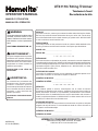
WARNING:
The engine exhaust from this product
contains chemicals known to the
State of California to cause cancer,
birth defects, or other reproductive
harm.
CALIFORNIA PROPOSITION 65
SERVICE
For parts or service, contact your nearest Homelite authorized service dealer.
Be sure to provide all relevant information when you call or visit. For the loca-
tion of the authorized service dealer nearest you, please call 1-800-242-4672
or visit us online at www.homelite.com.
REPAIR PARTS
The model number of this product is found on a plate or label attached to the
housing. Please record the serial number in the space provided below.
MODEL NO. _________________________________
SERIAL NO. _________________________________
DÉPANNAGE
Pour tout entretien ou réparation du produit, contacter le centre de réparations
Homelite agréé le plus proche. Veiller à fournir toutes les informations pertinentes
lors de tout appel téléphonique ou visite. Pour obtenir l’adresse du centre de
réparations agréé le plus proche, téléphoner au 1-800-242-4672, ou visiter
notre site www.homelite.com.
PIÈCES DE RECHANGE
Le numéro de modèle se trouve sur une plaquette ou étiquette placée sur le
bâti. Noter le numéro de série dans l’espace ci-dessous.
NUMÉRO DE MODÈLE ______________________
NUMÉRO DE SÉRIE _________________________
SERVICIO
Para obtener piezas o servicio, comuníquese con el centro de servicio
autorizado de Homelite más cercano. Asegúrese de proporcionar todos los
datos pertinentes al llamar o al presentarse personalmente. Para obtener
información sobre el establecimiento de servicio autorizado más cercano a
usted, le suplicamos llamar al 1-800-242-4672 o visitar nuestro sitio en la red
mundial, en la dirección www.homelite.com.
PIEZAS DE REPUESTO
El número de modelo de este producto se encuentra en una placa o etiqueta
pegada a la caja del motor. Le recomendamos anotar el número de serie en
el espacio suministrado abajo.
NÚMERO DE MODELO ______________________
NÚMERO DE SERIE _________________________
AVERTISSEMENT :
Les gaz d’échappement de ce produit
contiennent des produits chimiques
identifiés par l’état de Californie comme
causes de cancer, de malformations
congénitales et d’autres troubles de
l’appareil reproducteur.
PROPOSITION 65 DE L’ÉTAT DE
CALIFORNIE
ADVERTENCIA:
Las emanaciones provenientes del
escape del motor de este producto
contienen sustancias químicas
reconocidas por el estado de California
como causantes de cáncer, defectos
congénitos y otras afecciones del
aparato reproductor.
CALIFORNIA - PROPUESTA DE LEY
NÚM. 65
OPERATOR’S MANUAL
MANUEL D’UTILISATION
MANUAL DEL OPERADOR
UT41110 / String Trimmer
Tondeuse à fouet
Recortadora de hilo
-
 1
1
-
 2
2
-
 3
3
-
 4
4
-
 5
5
-
 6
6
-
 7
7
-
 8
8
-
 9
9
-
 10
10
-
 11
11
-
 12
12
-
 13
13
-
 14
14
-
 15
15
-
 16
16


Homelite ut41110 Owner's manual
- Category
- Grass trimmers
- Type
- Owner's manual
Ask a question and I''ll find the answer in the document
Finding information in a document is now easier with AI
Related papers
-
Homelite ut41799 Owner's manual
-
-
-
-
-
-
-
-
-
Other documents
-
Greenworks Grass trimmer/edger Owner's manual
-
-
 Menards 15" 5.5A Owner's manual
-
-
Ryobi RY41130 User manual
-
-
-
Craftsman CMEST900 Owner's manual
-
-
