Page is loading ...

Millerfi
October
1989
FORM:
OM-1548A
Effective
With
Serial
Number
JK661802
MODEL:
AUTOMATIC
1
DA-PS
Gas/Current
Sensing
Control
Hub
&
Spindle
Assembly
Spool
Support
OWNERS
MANUAL
IMPORTANT:
Read
and
understand
the
entire
contents
of
both
this
manual
and
the
power
source
manual
used
with
this
unit,
with
special
emphasis
on
the
safety
material
throughout
both
manuals,
before
Installing,
operating,
or
maintaining
this
equipment.
This
unit
and
these
instructions
are
for
use
only
by
persons
trained
and
experienced
In
the
sale
operation
of
welding
equip
ment.
Do
not
aiiow
untrained
persons
to
instail,
operate,
or
maintain
this
unit.
Contact
your
distributor
if
you
do
not
fully
understand
these
instructions.
MILLER
ELECTRIC
Mfg.
Co.
A
MitIe~
Gro~
L%d.
Con~as~y
P.O.
Box
1079
Appleton,
WI
54912
USA
Tel.
414-734-9821
PRINTED
IN
U.S.A

LIMITED
WARRANTY
EFFECTIVE:
MARCH
15,
1989
1~
This
warranty
supersedes
all
previous
MILLER
warranties
and
is
exclusive
with
no
other
guarantees
or
warranties
expressed
or
implied.
LIMITED
WARRANTY
Subject
to
the
terms
and
conditions
hereof,
Miller
Electric
Mfg.
Co.,
Appleton,
Wisconsin
warrants
to
its
Distributor/Dealer
that
all
new
and
unused
Equipment
fur
nished
by
Miller
is
free
from
defect
in
workmanship
and
material
as
of
the
time
and
place
of
delivery
by
Miller.
No
warranty
is
made
by
Miller
with
respect
to
engines,
trade
accessories
or
other
items
manufactured
by
others.
Such
engines,
trade
ac
cessories
and
other
items
are
sold
subject
to
the
warranties
of
their
respective
manufacturers,
if
any.
All
engines
are
war
ranted
by
their
manufacturer
for
one
year
from
date
of
original
purchase,
except
Tecumseh
and
Onan
engines
which
have
a
two
year
warranty.
,
Except
as
specified
below,
Millers
warranty
does
not
apply
to
components
having
normal
useful
life
of
less
than
one
(1)
year,
such
as
spot
welder
tips,
relay
and
contactor
points,
MILLER
MATC
parts
that
come
in
contact
with
the
welding
wire
includ
ing
nozzles
and
nozzle
insulators
where
failure
does
not
result
from
defect
in
workmanship
or
material,
Miller shall
be
required
to
honor
warranty
claims
on
warranted
Equipment
in
the
event
of
failure
resulting
from
a
defect
within
the
following
periods
from
the
date
of
delivery
of
Equipment
to
the
original
user:
1.
Arc
welders,
power
sources,
robots,
and
1
year
components
2.
Loadbanks
lyear
3.
Original
main
power
rectifiers
3
years
(labor
1
year
only)
4.
All
welding
guns,
feeder/guns
and
torches
90
days
5.
All
other
Millermatic
Feeders
1
year
6.
Replacement
or
repair
parts,
exclusive
of
labor
60
days
7.
Batteries
6
months
provided
that
Miller
is
notified
in
writing
within
thirty
(30)
days
of
the
date
of
such
failure.
As
a
matter
of
general
policy
only,
Miller
may
honor
claims
submitted
by
the
original
user
within
the
foregoing
periods.
In
the
case
of
Millers
breach
of
warranty
or
any
other
duty
with
respect
to
the
quality
of
any
goods,
the
exclusive
remedies
therefore
shall
be,
at
Millers
option
(1)
repairor
(2)
replacement
or,
where
authorized
in
writing
by
Miller
in
appropriate
cases,
(3)
the
reasonable
cost
of
repair
or
replacement
at
an
authorized
Miller
service
station
or(4)
payment
of
or
credit
for
the
purchase
price
(less
reasonable
depreciation
based
upon
actual
use)
upon
return
of
the
goods
at
Customers
risk
and
expense.
MILLERs
option
of
repair
or
replacementwill
be
FOB.,
Factory
at
Appleton,
Wisconsin,
or
F.O.
B.
at
a
MILLER
authorized
serv
ice
facility,
therefore,
no
compensation
for
transportation
costs
of
any
kind
will
be
allowed.
Upon
receipt
of
notice
of
apparent
defect
or
failure,
Miller
shall
instruct
the
claimant
on
the
war
ranty
claim
procedures
to
be
followed.
ANY
EXPRESS
WARRANTY
NOT
PROVIDED
HEREIN
AND ANY
IMPLIED
WARRANTY
GUARANTY
OR
REPRE
SENTATION
AS TO
PERFORMANCE,
AND
ANY
REMEDY
FOR
BREACH OF
CONTRACT
WHICH,
BUT
FOR
THIS
PRO
VISION,
MIGHT
ARISE
BY
IMPLICATION,
OPERATION
OF
LAW,
CUSTOM
OF
TRADE
OR
COURSE
OF
DEALING,
IN
CLUDING
ANY
IMPUED
WARRANTY
OF
MERCHAN
TABILITY
OR
OF
FITNESS
FOR
PARTICULAR
PURPOSE,
WITH
RESPECT
TO
ANY
AND
ALL
EQUIPMENT
FUR
NISHED
BY
MILLER
IS
EXCLUDED
AND
DISCLAIMED
BY
MILLER.
EXCEPT
AS
EXPRESSLY
PROVIDED
BY
MILLER
IN
WRITING,
MILLER
PRODUCTS
ARE
INTENDED
FOR
ULTI
MATE
PURCHASE
BY
COMMERCIAL/INDUSTRIAL
USERS
AND
FOR
OPERATION
BY
PERSONS
TRAINED
AND
EXPE
RIENCED
IN
THE
USE
AND
MAINTENANCE
OF
WELDING
EQUIPMENT
AND
NOT
FOR
CONSUMERS
OR
CON
SUMER
USE.
MILLERS
WARRANTIES
DO
NOT
EXTEND
TO,
AND
NO
RESELLER
IS
AUTHORIZED
TO
EXTEND
MILLERS
WARRANTIES
TO,
ANY
CONSUMER.
1.
I

OM.1548A-
IW~O
RECEIVING-HANDLING
Before
unpacking
equipment,
check
carton
for
any
dam-
Use
the
following
spaces
to
record
the
Model
Designa
age
that
may
have
occurred
during
shipment.
File
any
tion
and
Serial
or
Style
Number
of
your
unit.
The
infor
claims
for
loss
or
damage
with
the
delivering
carrier.
mation
is
located
on
the
data
card
or
the
nameplate.
Assistance
for
filing
or
settling
claims
may
be
obtained
from
the
distributor
and/or
the
equipment
manufactur-
Model
______________________________
ers
Transportation
Department.
Senal
or
Style
No.
___________________
When
requesting
information
about
this
equipment,
al
ways
provide
the
Model
Description
and
Serial
or
Style
Date
of
Purchase
____________________
Number.
TABLE
OF
CONTENTS
Section
No.
Page
No.
SECTION
1
-
SAFETY
RULES
FOR
OPERATION
OF
ARC
WELDING
POWER
SOURCE
1-1.
Introduction
1
1-2.
General
Precautions
1
1-3.
Arc
Welding
4
1-4.
Standards
Booklet
index
5
SECTION
2SAFETY
PRECAUTIONS
AND
SIGNAL
WORDS
2-1.
General
Information
And
Safety
6
2-2.
Safety
Alert
Symbol
And
Signal
Words
6
SECTION
3
SPECIFICATIONS
3-1.
Description
7
SECTION
4-INSTALLATION
4-1.
Site
Selection
9
4-2.
Equipment
Installation
9
4-3. Internal
Connections
10
4-4.
Wire
Drive
Motor
Speed
Calibration
Selection
12
4-5.
Weld
Control
Interconnections
13
4-6.
Gas/Current
Sensing
Control
Interconnections
14
4-7.
Welding
Wire
Installation
15
SECTION
5-OPERATOR
CONTROLS
5-1.
Power
Switch
And
Pilot
Light
15
5-2.
Retract
-
Advance
Switch
And
Jog
Switch
15
5-3.
Purge
Switch
16
5-4.
Start
Switch
16
5-5.
Stop
Switch
16
5-6.
Press
To
Set
Buttons
16
5-7.
Digital
Meters
16
5-8.
Run
In
Wire
Speed
Control
17
5-9.
Weld
Wire
Speed
Control
17
5-10.
Weld
Background
Voltage
Control
17

Section
No.
Page
No.
SECTION
5-
OPERATOR
CONTROLS
(Continued)
5-11.
Weld
Peak
Amperage
Control
17
5-12.
Crater
&
Jog
Wire
Speed
Control
17
5-13.
Crater
Background
Voltage
Control
17
5-14.
Crater
Peak
Amperage
Control
17
5-15.
PrefiowTimeControl
17
5-16.
Spot
-
Continuous
Switch
17
5-17.
SpotlimeControl
17
5-18.
Crater
Time
Control
17
5-19.
Burnback
Control
17
5-20.
Postfiow
Time
Control
17
5-21.
Optional
Run
In
Controls
18
SECTION
6
SEQUENCE
OF
OPERATION
6-1.
Gas
Metal
Arc
Welding
(GMAW)
And
Flux
Cored
Arc
Welding
(FCAW)
-
Continuous
19
6-2.
Gas
Metal
Arc
Welding
(GMAW)
And
Flux
Cored
Arc
Welding
(FCAW)
-
Spot
19
6-3.
Shutting
Down
19
SECTION
7
MAINTENANCE
&
TROUBLESHOOTING
7-1.
Routine
Maintenance
20
7-2.
Overload
Protection
20
7-3.
Hub
Reinstallation
20
7-4.
Circuit
Board
Handling
Precautions
21
7-5.
Troubleshooting
21
SECTION
8
ELECTRICAL
DIAGRAMS
Diagram
8-1.
Circuit
Diagram
23
Diagram
8-2.
Winng
Diagram
24
Diagram
8-3.
Circuit
Diagram
For
Models
With
Run
In
Option
26
Diagram
8-4.
Circuit
Diagram
For
Motor
Control
Board
PC2
27
Diagram
8-5.
Circuit
Diagram
For
Timer
Board
PC3
28
Diagram
8-6.
Circuit
Diagram
For
Tach
Board
PC4
29
Diagram
8-7.
Circuit
Diagram
For
Relay
Board
PC5
29
Diagram
8-8.
Circuit
Diagram
For
Low
Speed
Calibration
Board
PC8
30
SECTION
9
PARTS
LIST
Figure
9-1.
Control
Box
32
Figure
9-2.
Meter,
Volt-Digital
35
Figure
9-3.
Panel,
W/Components
36
Figure
9-4.
Circuit
Card,
Motor
Speed
PC2
37
Figure
9-5.
Circuit
Card,
Relay
39
Figure
9-6.
Circuit
Card,
Timer
PC3
40
Figure
9-7.
Circuit
Card
41
Figure
9-8.
Control,
Gas/Shunt
42
Figure
9-9.
Hub
&
Spindle
Assembly
43
Figure
9-10.
Reel,
Wire
44
Figure
9-11.
Circuit
Card
Low
Speed
Motor
Calibration
PC8
44
LIST
OF
CHARTS
AND
TABLES
Table
3-1.
Specifications
7
Table
3-2.
Weld
Parameters
7
Table
7-1.
Troubleshooting
21

SECTION
1
SAFETY
RULES
FOR
OPERATION
OF
ARC
WELDING
POWER
SOURCE
I-i.
INTRODUCTION
We
learn
by
experience.
Learning
safety
through
per
sonal
experience,
like
a
child
touching
a
hot
stove
is
harmful,
wasteful,
and
unwise..Let
the
experience
of
oth
ers
teach
you.
Safe
practices
developed
from
experience
in
the
use
of
welding
and
cutting
are
described
in
this
manual.
Re
search,
development,
and
field
experience
have
evolved
reliable
equipment
and
safe
installation,
opera
tion,
and
servicing
practices.
Accidents
occur
when
equipment
is
improperly
used
or
maintained.
The
rea
son
for
the
safe
practices
may
not
always
be
given.
Some
are
based
on
common
sense,
others
may
require
technical
volumes
to
explain.
It
is
wiser
to
follow
the
rules.
Read
and
understand
these
safe
practices
before
at
tempting
to
install,
operate,
or
service
the
equipment.
Comply
with
these
procedures
as
applicable
to
the
par
ticular
equipment
used
and
their
instruction
manuals,
for
personal
safety
and
for
the
safety
of
others.
Failure
to
observe
these
safe
practices
may
cause
seri
ous
injury
or
death.
When
safety
becomes
a
habit,
the
equipment
can
be
used
with
confidence.
These
safe
practices
are
divided
into
two
Sections:
1-General
Precautions,
common
to
arc
welding
and
cut
ting;
and
2-Arc
Welding
(and
Cutting)
(only).
Reference
standards:
Published
Standards
on
safety
are
also
available
for
additional
and
more
complete
pro
cedures
than those
given
in
this
manual.
They
are
listed
in
the
Standards
Index
in
this
manual.
ANSI
Z49.1
is
the
most
complete.
The
National
Electrical
Code,
Occupational
Safety
and
Health
Administration,
local
industrial
codes,
and
local
inspection
requirements
also
provide
a
basis
for
equip
ment
installation,
use,
and
service.
1-2.
GENERAL
PRECAUTIONS
Different
arc
welding
processes,
electrode
alloys,
and
fluxes
can
produce
different
fumes,
gases,
and
radiatIon
levels.
in
addItion
to
the
InformatIon
in
thIs
manual,
be
sure
to
consult
flux
and
electrode
manu
facturers
MaterIal
Safety
Data
Sheets
(MSDS5)
for
specific
technical
data
and
precautIonary
measures
concerning
their
materIal.
A.
Burn
Prevention
Wear
protective
clothing-gauntlet
gloves
designed
for
use
in
welding,
hat,
and
high
safety-toe
shoes.
Button
shirt
collar
and
pocket
flaps,
and
wear
cutf
less
trousers
to
avoid
entry
of
sparks
and
slag.
Wear
helmet
with
safety
goggles
and
glasses
with
side
shields
underneath,
appropriate
filter
lenses
or
plates
(protected
by
clear
cover
glass).
This
is
a
MUST
for
welding
or
cutting,
(and
chipping)
to
protect
the
eyes
from
radiant
energy
and
flying
metal.
Replace
cover
glass
when
broken,
pitted,
or
spattered.
See
1-3A.2.
Avoid
oily
or
greasy
clothing.
A
spark
may
ignite
them.
Hot
metal
such
as
electrode
stubs
and
workpieces
should
never
be
handled
without
gloves.
Medicai
first
aid
and
eye
treatment.
First
aid
facilities
and
a
qualified
first
aid
person
should
be
available
for
each
shift
unless
medical
facilities
are
close
by
for
immediate
treatment
of
flash
burns
of
the
eyes
and
skin
burns.
Ear
plugs
should
be
worn
when
working
on
overhead
or
in
a
confined
space.
A
hard
hat
should
be
worn
when
others
work
overhead.
Flammable
hair
preparations
should
not
be
used
by
per
sons
intending
to
weld
or
cut.
B.
Toxic
Fume
Prevention
Severe
discomfort,
illness
or
death
can
result
from
fumes,
vapors,
heat,
or
oxygen
enrichment
or
depletion
that
welding
(or
cutting)
may
produce.
Prevent
themwith
adequate
ventilation
as
described
in
ANSI
Standard
Z49.1
listed
in
Standards
Index.
NEVER
ventilate
with
oxygen.
Lead
-,
cadmium
-,
zinc-,
mercury-,
and
beryllium-bear
ing
and
similar
materials,
when
welded
(orcut)
may
pro
duce
harmful
concentrations
of
toxic
fumes.
Adequate
local
exhaust
ventilation
must
be
used,or
each
person
in
the
area as
well
as
the
operator
must
wear
an
air-sup
plied
respirator.
For
beryliium,
both
must
be
used.
Metals
coated
with
orcontaining
materials
that
emit
toxic
fumes
should
not
be
heated
unless
coating
is
removed
from
the
work
surface,
the
area
is
well
ventilated
and,
if
necessary,
while
wearing
an
air-supplied
respirator.
Work
in
a
confined
space
only
while
it
is
being
ventilated
and,
if
necessary,
while
wearing
an
air-supplied
respira
tor.
Gas
leaks
in
a
confined
space
should
be
avoided.
Leaked
gas
in
large
quantities
can
change
oxygen
con
centration
dangerously.
Do
not
bring
gas
cylinders
into
a
confined
space.
Leaving
confined
space,
shut
OFF
gas
Supply
at
source
to
prevent
possible
accumulation
of
gases
in
the
space
if
downstream
valves
have
been
accidentally
opened
or
left
open.
Check
to
be
sure
that
the
space
is
safe
before
re-entering
it.
Vapors
from
chlorinated
solvents
can
be
decomposed
by
the
heat
of
the
arc
(or
flame)
to
form
PHOSGENE,
a
highly
toxic
gas,
and
other
lung
and
eye
irritating
prod
ucts.
The
ultraviolet
(radiant)
energy
of
the
arc
can
also
decompose
trichioroethyiene
and
perchloroethyiene
vapors
to
form
phosgene.
DO
NOT
WELD
or
cut
where
solvent
vapors
can
be
drawn
into
the
welding
or
cutting
atmosphere
or
where
the
radiant
energy
can
penetrate
OM-1548
Page
1

to
atmospheres
containing
even
minute
amounts
of
tnchloroethylene
or
perchloroethylene.
C.
Fire
and
Explosion
Prevention
Causes
of
fire
and
explosion
are:
combustibles
reached
by
the
arc,
flame,
flying
sparks,
hot
slag
or
heated
mate
nal;
misuse
of
compressed
gases
and
cylinders;
and
short
circuits.
BE
AWARE
THAT
flying
sparks
or
falling
slag
can
pass
through
cracks,
along
pipes,
throughwindows
ordoors,
and
through
wall
or
floor
openings,
out
of
sight
of
the
goggled
operator.
Sparks
and
slag
can
fly
35
feet.
To
prevent
fires
and
explosion:
Keep
equipment
clean
and
operable,
free
of
oil,
grease,
and
(in
electrical
parts)
of
metallic
particles
that
can
cause
short
circuits.
If
combustibles
are
in
area,
do
NOT
weld
or
cut.
Move
the
work
if
practicable,
to
an
area
free
of
combustibles.
Avoid
paint
spray
rooms,
dip
tanks,
storage
areas,
venti
lators.
If
the
work
cannot
be
moved,
move
combustibles
at
least
35
feet
away
out
of
reach
of
sparks
and
heat;
or
protect
against
ignition
with
suitable
and
snug-fitting,
fire-resistant
covers
or
shields.
Walls
touching
combustibles
on
opposite
sides
should
not
be
welded
on
(or
cut).
Walls,
ceilings,
and
floor
near
work
should
be
protected
by
heat-resistant
covers
or
shields.
Fire
watcher
must
be
standing
by
with
suitable
fire
extin
guishing
equipment
during
and
for
some
time
afterweld
ing
or
cutting
it:
a.
appreciable
combustibles
(including
building
construction)
are
within
35
feet
b.
appreciable
combustibles
are
further
than
35
feet
but
can
be
ignited
by
sparks
c.
openings
(concealed
orvisible)
in
floors
orwalls
within
35
feet
may
expose
combustibles
to
sparks
d.
combustibles
adjacent
to.walis,
ceilings,
roofs,
or
metal
partitions
can
be
ignited
by
radiant
or
conducted
heat.
Hot
work
permit
should
be
obtained
before
operation
to
ensure
supervisors
approval
that
adequate
precautions
have
been
taken.
After
work
is
done,
check
that
area
is
free
of
sparks,
glowing
embers,
and
flames.
An
empty
container
that
held
combustibles,
or
that
can
produce
flammable
or
toxic
vapors
when
heated,
must
never
be
welded
on
or
cut,
unless
container
has
first
been
cleaned
as
described
in
AWS
Standard
A6.O,
listed
7
in
Standards
Index.
This
includes:
athorough
steamorcausticcleaning(ora
solvent
or
water
washing,
depending
on
the
combusti
bles
solubility)
followed
by
purging
and
inerting
with
ni
trogen
or
carbon
dioxide,
and
using
protective
equip-
ment
as
recommended
in
A6.O.
Waterfilling
just
below
working
level
may
substitute
for
inerting.
A
container
with
unknown
contents
should
be
cleaned
(see
preceding
paragraph).
Do
NOT
depend
on
sense
of
smell
or
sight
to
determine
if
it
is
safe
to
weld
or
cut.
Hollow
castings
or
containers
must
be
vented
before
welding
or
cutting.
They
can
explode.
Explosive
atmospheres.
Never
weld
or
cut
where
the
air
may
contain
flammable
dust,
gas,
or
liquid
vapors
(such
as
gasoline).
D.
Compressed
Gas
Equipment
Standard
precautions.
Comply
with
precautions
in
this
manual,
and
those
detailed
in
CGA
Standard
P-i,
SAFE
HANDLING
OF
COMPRESSED
GASES
IN
CYLIN
DERS,
listed
ii
in
Standards
Index.
1.
Pressure
Regulators
Regulator
relief
valve
is
designed
to
protect
only
the
regulator
from
overpressure;
it
is
not
intended
to
protect
any
downstream
equipment.
Provide
such
protection
with
one
or
more
relief
devices.
Never
connect
a
regulator
to
a
cylinder
containing
gas
other
than
that
for
which
the
regulator
was
designed.
Remove
faulty
regulatorfrom
service
immediately
for
re
pair
(first
close
cylinder
valve).
The
following
symptoms
indicate
a
faulty
regulator:
Leaks-if
gas
leaks
externally.
Excessive
Creep-if
delivery
pressure
continues
to
rise
with
downstream
valve
closed.
Faulty
Gauge-if
gauge
pointer
does
not
move
off
stop
pin
when
pressurized,
nor
returns
to
stop
pin
after
pressure
release.
Repair.
Do
NOT
attempt
to
repair.
Send
faulty
regulators
for
repair
to
manufacturers
designated
repair
center,
where
special
techniques
and
tools
are
used
by
trained
personnel.
2.
Cylinders
Cylinders
must
be
handled
carefully
to
prevent
leaks
and
damage
to
their
walls,
valves,
or
safety
devices:
Avoid
electrical
circuit
contact
with
cylinders
including
third
rails,
electrical
wires,
or
welding
circuits.
They
can
produce
short
circuit
arcs
that
may
lead
to
a
serious
acci
dent.
(See
1-3C.)
ICC
or
DOT
marking
must
be
on
each
cylinder.
It
is
an
assurance
of
safety
when
the
cylinder
is
properly
han
dled.
Identifying
gas
content.
Use
only
cylinders
with
name
of
gas
marked
on
them;
do
not
rely
on
color
to
identify
gas
content.
Notify
supplier
if
unmarked.
NEVER
DEFACE
or
alter
name,
number,
or
other
markings
on
a
cylinder.
It
is
illegal
and
hazardous.
Empties:
Keep
valves
closed,
replace
caps
securely;
mark
MT;
keep
them
separate
from
FULLS
and
return
promptly.
OM-1548
Page
2

Prohibited
use.
Never
use
a
cylinder
or
its
contents
for
other
than
its
intended
use,
NEVER
as a
support
or
roller.
Locate
or
secure
cylinders
so
they
cannot
be
knocked
over.
Passageways
and
work
areas.
Keep
cylinders
clear
of
areas
where
they
may
be
struck.
Transporting
cylinders.
With
a
crane,
use
a
secure
sup
port
such
as a
platform
orcradle.
Do
NOT
lift
cylinders
off
the
ground
by
their
valves
or
caps,
or
by
chains,
slings,
or
magnets.
Do
NOT
expose
cylinders
to
excessive
heat,
sparks,
slag,
and
flame,
etc.
that
may
cause
rupture.
Do
not
al
low
contents
to
exceed
130F.
Cool
with
water
spray
where
such
exposure
exists.
Protect
cylinders
particularly
valves
from
bumps,
falls,
falling
objects,
and
weather.
Replace
caps
securely
when
moving
cylinders.
Stuck
valve.
Do
NOT
use
a
hammer
or
wrench
to
open
a
cylinder
valve
that
can
not
be
opened
by
hand.
Notify
your
supplier.
Mixing
gases.
Never
try
to
mix
any
gases
in
a
cylinder.
Never
refill
any
cylinder.
Cylinderfittings
should
never
be
modified
or
exchanged.
3.
Hose
Prohibited
use.
Never
use
hose
other
than
that
designed
for
the
specified
gas.
A
general
hose
identification
rule
is:
red
for
fuel
gas,
green
for
oxygen,
and
black
for
inert
gases.
Use
ferrules
or
clamps
designed
for
the
hose
(not
ordi
nary
wire
or
other
substitute)
as
a
binding
to
connect
hoses
to
fittings.
No
copper
tubing
splices.
Use
only
standard
brass
fit
tings
to
splice
hose.
Avoid
long
runs
to
prevent
kinks
and
abuse.
Suspend
hose
off
ground
to
keep
it
from
being
run
over,
stepped
on,
or
otherwise
damaged.
Coil
excess
hose
to
prevent
kinks
and
tangles.
Protect
hose
from
damage
by
sharp
edges,
and
by
sparks,
slag,
and
open
flame.
Examine
hose
regularly
for
leaks,
wear,
and
loose
con
nections.
Immerse
pressured
hose
in
water;
bubbles
in
dicate
leaks.
Repair
leaky
or
worn
hose
by
cutting
area
out
and
splic
ing
(1-2D3).
Do
NOT
tape.
4.
Proper
Connections
Clean
cylinder
valve
outlet
of
impunties
that
may
clog
orifices
and
damage
seats
before
connecting
regulator.
Except
for
hydrogen,
crack
valve
momentarily,
pointing
outlet
away
from
people
and
sources
of
ignition.
Wipe
with
a
clean
lintless
cloth.
Match
regulator
to
cylinder.
Before
connecting,
check
that
the
regulator
label
and
cylinder
marking
area,
and
thatthe
regulator
inlet
and
cylinderoutlet
match.
NEVER
CONNECT
a
regulator
designed
for
a
particular
gas
or
gases
to
a
cylinder
containing
any
other
gas.
Tighten
connections.
When
assembling
threaded
con
nections,
clean
and
smooth
seats
where
necessary.
Tighten.
If
connection
leaks,
disassemble,
clean,
and
retighten
using
properly
fitting
wrench.
Adapters.
Use
a
CGA
adapter
(available
from
your
sup
plier)
between
cylinder
and
regulator,
if
one
is
required.
usetwowrenchestotighten
adaptermarked
RIGHTand
LEFT
HAND
threads.
Regulatoroutiet
(or
hose)
connections
may
be
identified
by
right
hand
threads
for
oxygen
and
left
hand
threads
(with
grooved
hex
on
nut
or
shank)
for
fuel
gas.
5.
Pressurizing
Steps:
Drain
regulator
of
residual
gas
through
suitable
vent
be
fore
opening
cylinder
(or
manifold
valve)
by
turning
ad
justing
screw
in
(clockwise).
Draining
prevents
exces
sive
compression
heat
at
high
pressure
seat
by
allowing
seat
to
open
on
pressurization.
Leave
adjusting
screw
engaged
slightly
on
single-stage
regulators.
Stand
to
side
of
regulator
while
opening
cylinder
valve.
Open
cylinder
valve
slowly
so
that
regulator
pressure
in
creases
slowly.
When
gauge
is
pressurized
(gauge
reaches
regulator
maximum)
leave
cylinder
valve
in
fol
lowing
position:
For
oxygen
and
inert
gases,
open
fully
to
seal
stem
against possible
leak.
For
fuel
gas,
open
to
less
than
one
turn
to
permit
quick
emergency
shutoff.
Use
pressure
charts
(available
from
your
supplier)
for
safe
and
efficient,
recommended
pressure
settings
on
regulators.
Check
for
leaks
on
first
pressurization
and
regularly
there-after.
Brush
with
soap
solution
(capfuli
of
Ivory
Liq
uid*
or
equivalent
per
gallon
of
water).
Bubbles
indicate
leak.
Clean
off
soapy
water
after
test:
dried
soap
is
com
bustible.
E.
User
Responsibilities
Remove
leaky
or
defective
equipment
from
service
im
mediately
for
repair.
See
User
Responsibility
statement
in
equipment
manual.
F.
Leaving
Equipment
Unattended
Close
gas
supply
at
source
and
drain
gas.
G.
Rope
Staging-Support
Rope
staging-support
should
not
be
used
for
welding
or
cutting
operation;
rope
may
burn.
*Trademark
of
Proctor
&
Gamble.
OM-1548
Page
3

1-3.
ARC
WELDING
Comply
with
precautions
in
1-1,
1-2,
and
this
section.
Arc
Welding,
properly
done,
is
a
safe
process,
but
a
careless
operator
invites
trouble.
The
equipment
carries
high
currents
at
significant
voltages.
The
arc
is
very
bright
and
hot.
Sparks
fly,
fumes
rise,
ulUavioiet
and
in
frared
energy
radiates,
weldments
are
hot,
and
com
pressed
gases
may
be
used.
The
wise
operator
avoids
unnecessary
risks
and
protects
himself
and
others
from
accidents.
Precautions
are
described
here
and
in
stan
dards
referenced
in
index.
A.
Burn
ProtectIon
Comply
with
precautions
in
1-2.
The
welding
arc
is
intense
and
visibly
bright.
Its
radiation
can
damage
eyes,
penetrate
lightweight
clothing,
reflect
from
light-colored
surfaces,
and
burn
the
skin
and
eyes.
Skin
burns
resemble
acute
sunburn,
those
from
gas-
shielded
arcs
are
more
severe
and
painful.
DONT
GET
BURNED;
COMPLY
WITH
PRECAUTIONS.
1.
Protective
Clothing
Wear
long-sleeve
clothing
(particularly
for
gas-shielded
arc)
in
addition
to
gloves,
hat,
and
shoes
(1
-2A).
As
nec
essary,
use
additional
protective
clothing
such
as
leather
jacket
or
sleeves,
flame-proof
apron,
and
f
ire-re
sistant
leggings.
Avoid
outer
garments
of
untreated
cot
ton.
Bare
skin
protection.
Wear
dark,
substantial
clothing.
Button
collar
to
protect
chest
and
neck
and
button
pock
ets
to
prevent
entry
of
sparks.
2.
Eye
and
Head
Protection
Protect
eyes
from
exposure
to
arc.
NEVER
look
at
an
electric
arc
without
protection.
Welding
helmet
or
shield
containing
a
filter
plate
shade
no.
12
or
denser
must
be
used
when
welding.
Place
over
face
before
striking
arc.
Protect
filter
plate
with
a
clear
cover
plate.
Cracked
or
broken
helmet
or
shield
should
NOT
be
worn;
radiation
can
pass
through
to
cause
burns.
Cracked,
broken,
or
loose
filter
plates
must
be
replaced
IMMEDIATELY.
Replace
clear
cover
plate
when
broken,
pitted,
or
spattered.
Flash
goggles
with
side
shields
MUST
be
worn
under
the
helmet
to
give
some
protection
to
the
eyes
should
the
helmet
not
be
lowered
over
the
face
before
an
arc
is
struck.
Looking
at
an
arc
momentarily
with
unprotected
eyes
(particularly
a
high
intensity
gas-shielded
arc)
can
cause
a
retinal
burn
that
may
leave
a
permanent
dark
area
in
the
field
of
vision.
3.
Protection
of
Nearby
Personnel
Enclosed
welding
area.
For
production
welding,
a
sepa
rate
room
or
enclosed
bay
is
best.
in
open
areas,
sur
round
the
operation
with
low-reflective,
non-combusti
ble
screens
or
panels.
Allow
for
free
air
circulation,
par
ticularly
at
floor
level.
Viewing
the
weld.
Provide
face
shields
for
all
persons
who
will
be
looking
directly
at
the
weld.
Others
working
in
area.
See
that
all
persons
are
wearing
flash
goggles.
Before
starting
to
weld,
make
sure
that
screen
flaps
or
bay
doors
are
closed.
B.
Toxic
Fume
Prevention
Comply
with
precautions
in
1
-2B.
Generator
engine
exhaust
must
be
vented
to
the
outside
air.
Carbon
monoxide
can
kill.
C.
FIre
and
Explosion
Prevention
Comply
with
precautions
in
1
-2C.
Equipments
rated
capacity.
Do
not
overload
arc
welding
equipment.
it
may
overheat
cables
and
cause
a
fire.
Loose
cable
connections
may
overheat
or
flash
and
cause
a
fire.
Never
strike
an
arc
on
a
cylinder
or
other
pressure
ves
sel.
It
creates
a
brittle
area
that
can cause
a
violent
nip
ture
or
lead
to
such
a
rupture
under
rough
handling.
D.
Compressed
Gas
Equipment
Comply
with
precautions
in
1-20.
E.
Shock
Prevention
Exposed
hot
conductors
or
other
bare
metal
in
the
weld
ing
circuit,
or
in
ungrounded,
electrically-HOT
equip
ment
can
fatally
shock
a
person
whose
body
becomes
a
conductor.
DO
NOT
STAND,
SIT,
LIE,
LEAN
ON,
OR
TOUCH
a
wet
surface
when
welding,
without
suitable
protection.
To
protect
against
shock:
Wear
dry
insulating
gloves
and
body
protection.
Keep
body
and
clothing
dry.
Never
work
in
damp
area
without
adequate
insulation
against
electrical
shock.
Stay
on
a
dry
duckboard,
or
rubber
mat
when
dampness
or
sweat
can
not
be
avoided.
Sweat,
sea
water,
or
moisture
be
tween
body
and
an
electrically
HOT
part
or
grounded
metal
reduces
the
electrical
resistance,
and
could
en
able
dangerous
and
possibly
lethal
currents
to
flow
through
the
body.
A
voltage
will
exist
between
the
electrode
and
any
con
ducting
object
in
the
work
circuit.
Examples
of
conduct
ing
objects
include,
but
are
not
limited
to,
buildings,
elec
trical
tools,
work
benches,
welding
power
source
cases,
workpieces,
etc.
Never
touch
the
electrode
and
any
metal
object
unless
the
welding
power
source
is
off.
1.
Grounding
the
Equipment
Arc
welding
equipment
must
be
grounded
according
to
the
National
Electrical
Code,
and
the
work
must
be
grounded
according
to
ANSI
Z49.1
Safety
In
Welding
And
Cutting.
When
installing,
connect
the
frames
of
each
unit
such
as
welding
power
source,
control,
worktable,
and
water
cir
culator
to
the
building
ground.
Conductors
must
be
ade
quate
to
carry
ground
currents
safely.
Equipment
made
OM-1548
Page
4

electrically
HOT
by
stray
current
may
shock,
possibly
I
a-
tally.
Do
NOT
GROUND
to
electrical
conduit,
orto
a
pipe
carrying
ANY
gas
or
flammable
liquid
such
as
oil
or
fuel.
Three-phase
connection.
Check
phase
requirements
of
equipment
before
installing.
If
only
3-phase
power
is
available,
connect
single-phase
equipment
to
only
two
wires
of
the
3-phase
line.
Do
NOT
connect
the
equip
ment
ground
lead
to
the
third
(live)
wire,
or
the
equip
ment
will
become
electrically
HOT-a
dangerous
condi
tion
that
can
shock,
possibly
fatally.
Before
welding,
check
ground
for
continuity.
Be
sure
conductors
are
touching
bare
metal
of
equipment
frames
at
connections.
If
a
line
cord
with
a
ground
lead
is
provided
with
the
equipment
for
connection
to
a
switchbox,
connect
the
ground
lead
to
the
grounded
switchbox.
If
a
three-prong
plug
is
added
for
connection
to
a
grounded
mating
re
ceptacle,
the
ground
lead
must
be
connected
to
the
ground
prong
only.
If
the
line
cord
comes
with
a
three-
prong
plug,
connect
to
a
grounded
mating
receptacle.
Never
remove
the
ground
prong
from
a
plug,
or
use
a
plug
with
a
broken
off
ground
prong.
2.
Electrode
Holders
Fully
insulated
electrode
holders
should
be
used.
Do
NOT
use
holders
with
protruding
screws.
3.
Connectors
Fully
insulated
lock-type
connectors
should
be
used
to
join
welding
cable
lengths.
4.
Cables
Frequently
inspect
cables
for
wear,
cracks
and
damage.
IMMEDIATELY
REPLACE
those
with
excessively
worn
or
damaged
insulation
to
avoid
possibly-lethal
shock
from
bared
cable.
Cables
with
damaged
areas
may
be
taped
to
give
resistance
equivalent
to
original
cable.
Keep
cable
dry,
free
of
oil
and
grease,
and
protected
from
hot
metal
and
sparks.
5.
Terminals
And
Other
Exposed
Parts
Terminals
and
other
exposed
parts
of
electrical
units
should
have
insulating
covers
secured
before
operation.
6.
Electrode
a.
Equipment
with
output
on/off
control
(contactor)
Welding
power
sources
for
use
with
the
gas
metal
arc
welding
(GMAW),
gas
tungsten
arc
welding
(GTAW)
and
similar
processes
nor
mally
are
equipped
with
devices
that
permit
on
off
control
of
the
welding
poweroutput.
When
so
equipped
the
electrode
wire
becomes
electri
cally
HOT
when
the
power
source
switch
is
ON
and
the
welding
gun
switch
is
closed.
Never
touch
the
electrode
wire
or
any
conducting
ob
ject
in
contact
with
the
electrode
circuit
unless
the
welding
power
source
is
off.
b.
Equipment
without
output
on/off
control
(no
contacto
r)
Welding
power
sources
used
with
shielded
metal
arc
welding
(SMAW)
and
similar
proc
esses
may
not
be
equipped
with
welding
power
output
on-off
control
devices.
With
such
equip
ment
the electrode
is
electrically
HOT
when
the
power
switch
is
turned
ON.
Never
touch
the
electrode
unless
the
welding
power
source
is
off.
7.
Safety
Devices
Safety
devices
such
as
interlocks
and
circuit
breakers
should
not
be
disconnected
or
shunted
out.
Before
installation,
inspection,
or
service,
of
equipment,
shut
OFF
all
power
and
remove
line
fuses
(or
lock
or
red-
tag
switches)
to
prevent
accidental
turning
ON
of
power.
Disconnect
all
cables
from
welding
power
source,
and
pull
all
115
volts
tine-cord
plugs.
Do
not
open
power
circuit
or
change
polarity
while
weld
ing.
If,
in
an
emergency,
it
must
be
disconnected,
guard
against
shock
burns,
or
flash
from
switch
arcing.
Leaving
equipment
unattended.
Always
shut
OFF
and
disconnect
all
power
to
equipment.
Power
disconnect
switch
must
be
available
near
the
welding
power
source.
F.
Protection
For
Wearers
of
Electronic
Life
Sup
port
Devices
(Pacemakers)
Magnetic
fields
from
high
currents
can
affect
pacemaker
operation.
Persons
wearing
electronic
life
support
equipment
(pacemaker)
should
consult
with
their
doctor
before
going
near
arc
welding,
gouging,
or
spot
welding
operations.
1-4.
STANDARDS
BOOKLET
INDEX
For
more
information,
refer
to
the
following
standards
or
their
latest
revisions
and
comply
as
appiicable:
1.
ANSI
Standard
Z49.1,
SAFETY
IN
WELDING
AND
CUTTING
obtainable
from
the
American
Welding
Society,
550
N.W.
LeJeune
Rd,
Miami,
FL
33126.
2.
NIOSH,
SAFETY
AND
HEALTH
IN
ARC
WELDING
AND
GAS
WELDING
AND
CUTTING
obtainable
from
the
Superintendent
of
Documents,
U.S.
Gov
ernment
Printing
Office,
Washington,
D.C.
20402.
3.
OSHA,
SAFETY
AND
HEALTH
STANDARDS,
29CFR
1910,
obtainable
from
the
Superintendent
of
Documents,
U.S.
Government
Printing
Office,
Washington,
D.C.
20402.
4.
ANSI
Standard
Z87.1,
SAFE
PRACTICES
FOR
OCCUPATION
AND
EDUCATIONAL
EYE
AND
FACE
PROTECTION
obtainable
from
the
American
National
Standards
Institute,
1430
Broadway,
New
York,
NY
10018.
5.
ANSI
Standard
Z41.1,
STANDARD
FOR
MENS
SAFETY-TOE
FOOTWEAR
obtainable
from
the
American
National
Standards
Institute,
1430
Broad
way,
New
York,
NY
10018.
6.
ANSI
Standard
Z49.2,
FIRE
PREVENTION
IN
THE
USE
OF
CUTTING
AND
WELDING
PROCESSES
OM-1
548
Page
5

obtainable
from
the
American
National
Standards
Institute,
1430
Broadway,
New
York,
NY
10018.
7.
AWS
Standard
A6.0,
WELDING
AND
CUTTING
CONTAINERS
WHICH
HAVE
HELD
COMBUS
TIBLES
obtainable
from
the
American
Welding
So
ciety,
550
N.W.
LeJeune
Ad,
Miami,
FL
33126.
8.
NFPA
Standard
51,
OXYGEN-FUEL
GAS
SYS
TEMS
FOR
WELDING,
CUTTING,
AND
ALLIED
PROCESSES
obtainable
from
the
National
Fire
Protection
Association,
Batterymarch
Park,
Quincy,
MA
02269.
9.
NFPA
Standard
70,
NATIONAL
ELECTRICAL
CODE
obtainable
from
the
National
Fire
Protection
Association,
Batterymarch
Park,
Quincy,
MA
02269.
10.
NFPA
Standard
51B,
CUTTING
AND
WELDING
PROCESSES
obtainable
from
the
National
Fire
Protection
Association,
Batterymarch
Park,
Qui
ncy,
MA
02269.
11.
CGA
Pamphlet
P-i,
SAFE
HANDLING
OF
COM
PRESSED
GASES
IN
CYLINDERS
obtainable
from
the
Compressed
Gas
Association,
1235
Jeffer
son
Davis
Highway,
Suite
501,
Arlington,
VA
22202.
12.
CSA
Standard
W117.2,
CODE
FOR
SAFETY
IN
WELDING
AND
CUTTING
obtainable
from
the
Ca
nadian
Standards
Association,
Standards
Sales,
178
Rexdale
Boulevard,
Rexdale,
Ontario,
Canada
M9W
1R3.
13.
NWSA
booklet,
WELDING
SAFETY
BIBLIOGRA
PHY
obtainable
from
the
National
Welding
Supply
Association,
1900
Arch
Street,
Philadelphia,
PA
19103.
14.
American
Welding
Society
Standard
AWSF4.1,
RECOMMENDED
SAFE
PRACTICES
FOR
THE
PREPARATION
FOR
WELDING
AND
CUTTING
OF
CONTAINERS
AND
PIPINGTHAT
HAVE
HELD
HAZARDOUS
SUBSTANCES,
obtainable
from
the
American
Welding
Society,
550
N.W.
LeJeune
Rd,
Miami,
FL
33126.
15.
ANSI
Standard
Z88.2,
PRACTICE
FOR
RESPIRA
TORY
PROTECTION,
obtainable
from
the
Ameri
can
National
Standards
Institute,
1430
Broadway,
New
York,
NY
10018.
SECTION
2-
SAFETY
PRECAUTIONS
AND
SIGNAL
WORDS
2-1.
GENERAL
INFORMATION
AND
SAFETY
A.
General
Information
presented
in
this
manual
and
on
various
la
bels,
tags,
and
plates
on
the
unit
pertains
to
equipment
design,
installation,
operation,
maintenance,
and
troubleshooting
which
should
be
read,
understood,
and
followed
for
the
safe
and
effective
use
of
this
equipment.
B
.
Safety
The
installation,
operation,
maintenance,
and
trouble
shooting
of
arc
welding
equipment
requires
practices
and
procedures
which
ensure
personal
safety
and
the
safety
of
others.
Therefore,
this
equipment
is
to
be
in
stalled,
operated,
and
maintained
only
by
qualified
per
Sons
fl
accordance
with
this
manual
and
all
applicable
codes
such
as,
but
not
limited
to,
those
listed
at
the
end
of
Section
1
Safety
Rules
For
Operation
Of
Arc
Weld
ing
Power
Source.
2-2.
SAFETY
ALERT
SYMBOL
AND
SIGNAL
WORDS
The
following
safety
alert
symbol
and
signal
words
are
used
throughout
this
manual
to
call
attention
to
and
iden
tify
different
levels
of
hazard
and
special
instructions.
4~
This
safety
alert
symbol
is
used
with
the
signal
words
WARNING
and
CAUTION
to
call
atten
tion
to
the
safety
statements.
4A
WARNING
statements
identify
procedures
or
practices
which
must
be
followed
to
avoid
seri
ous
personal
injury
or
loss
of
life.
a
CAUTION
statements
identify
procedures
or
practices
which
must
be
followed
to
avoid
minor
personal
injury
or
damage
to
this
equipment.
IMPORTANT
statements
identify
special
instructions
necessary
for
the
most
efficient
operation
of
this
equip
ment.
OM-1548
Page
6

SECTION
3-
SPECIFICATIONS
Table
3-1.
SpecIfications
Component
Dimensions
Weight
Height
Width
Depth
Net
Ship
W
IdC
e
ontI~O
17-1/2iri.
(445
mm)
14
in.
(355
mm)
Bin.,
(203
mm)
32~1I2
lbs.
(14.7
kg)
Total
80
lbs.*
(36
kg)
Gas/Current
Sensing
Control
4-1/2
in.
(108
mm)
5-1/2
in.
(140
mm)
10-1/2
in.
(267
mm)
4-1/2
lbs.
(2.0
kg)
Spool
Support
Assembly+
13-31/2
in.
(343
mm)
8-3/4
in.
(222
mm)
8-1/2
in.
(216
mm)
6
lbs.
(2.7
kg)
Add
1
in.
(25
mm)
for
control
knobs.
Spool
Support
without
optional
wire
reel.
lncludes
weight
of
wire
drive
assembly.
A1D-2
A1D-4
50-780
ipm
(1
.8-19.8
mpm)
.023-3/32
in.
wire
Wire
Feed
Speed Range
(0.6-2.4
mm
wire)
A1D-2L
AID-4L
15-200
1pm
(0.4-5.1
mpm)
5/64-5/32
in.
wire
(2.0-4.0
mm
wire)
Weld
Voltage
And
Amperage
Capacity
.
Limited
by
welding
power
source.
3-1.
DESCRIPTION
This
weld
control
is
designed
to
automatically
cycle
welding
events
while
maintaining
constant
wire
teed
speed.
This
unit
is
to
be
used
with
the
Puistar
DC
con
stant
voltage
(CV)
welding
power
source
having
remote
contactor
and
voltage
control
capabilities
for
Gas
Metal
Arc
Welding
(GMAW),
Gas
Metal
Arc
Welding-Pulsed
(GMAW-P),
or
Submerged
Arc
Welding
(SAW).
The
standard
weld
contiDl
has
provisions
to
set
weld
parameters
according
to
Table
3-2.
Spot
weld
controls
are
also
standard.
Normally-open
and
normally-closed
relay
contacts
that
work
in
conjunction
with
the
weld
cycle
are
available
to
interlace
with
other
equipment
(such
as
fixtures).
Optional
controls
include
run
in
voltage
and
time,
and
water
valve.
Table
3-2.
Weld
Parameters
Weld
Cycle
Controls
Wire
Speed
Background
Voltage
Peak
Amperage
.~..
ime
Pref
low
X
,
Run-In
X
,
Weld
X
X
X
Crater
(Jog)
x
Burnback
X
Postf
low
X
Standard
=
Optional
For
information
on
the wire
drive
assembly,
see
Owners
Manual
supplied
with
the
wire
drive
assembly.
A
gas/current
sensing
control,
wire
spool
hub,
and
spindle
support
are
provided
with
the
weld
control.
The
wire
reel
is
optional.
OM-1548
Page
7

14
In.
TA-060
485-A
-
2.7/8
In.
__J
(73
mm)
I
TA.0~
440
Add
1
In.
(25
mm)
for
front
panel
controls.
AUTOMATIC
IDA-PS
Weld
Control
Gas/Current
Sensing
Control
TA-080
429
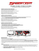
Overall
Dimensions
And
Mounting
Hole
Layout
Inches
Millimeters
A
21-7/8
556
B
13-3/4
349
C
3
76
D
2-1/2
63.5
E
3.1/2
88.9
F
4-1/2
114
G
10-11/16
275
TB-080
486-C
Figure
3-1.
Dimensional
Views
7-3/4
ln.~~
,~-~~~5-1/2
in.
(140
mm)
(197
mm)
(89
mm)
2
In.
TOP
VIEW
TE
4-1/2
in.
8in.
(203
mm)
TC-098
619-A
mm)
Diameter
2
Hol
(267
mm)
OM-1
548
Page
8

SECTION
4INSTALLATION
4-1.
SITE
SELECTION
(Figure
3-1
And
Figure
4-1)
Select
an
installation
site
which
provides
the
following:
1.
Correct
input
power
supply
(see
unit
nameplate)
2.
3.
4.
5.
6.
7.
Proper
temperature
that
avoids
extremes
of
heat
or
cold
8.
Proper
airflow
around
unit
9.
Adequate
space
to
open
and
remove
cover
and
wrapper
for
installation,
maintenance,
and
repair
functions.
Mounting
holes
provide
the
capability
to
install
and
se
cure
the
system
components
in
a
permanent
location.
Figure
3-1
gives
overall
dimensions
and
mounting
hole
layout.
4-2.
EQUIPMENT
INSTALLATION
A.
Supplied
Equipment
The
following
equipment
is
supplied
as
standard
and
re
quires
installation
or
assembly:
1.
Weld
Control
2.
Gas/Current
Sensing
Control
3.
Hub
and
Spindle
Assembly
4.
Spindle
Support
5.
10
ft.
(3
m)
Weld
Control
Gas/Current
Sensing
Control
Interconnecting
Cord
6.
Two
25
ft.
(8
m)
Weld
Control
Welding
Power
Source
Interconnecting
Cords
7.
5ft.(1.5m)
Motor
Cord
8.
lOft.(3m)GasHose
B.
Equipment
Location
(Figure
4-1)
When
deciding
on
equipment
location,
consider
the fol
lowing:
1.
The
equipment
must
be
mounted
to
a
structure
ca
pable
of
supporting
the
weight
of
the
equipment.
2.
The
lead
lengths
of
the
cords
supplied
with
the
equipment
will
limit
the
area
in
which
the
equipment
can
be
located.
Some
cords
can
be
extended
by
us
ing
optional
extension
cords
(check
with
welding
equipment
distributor).
3.
The
interconnecting
cords
must
be
routed
so
that
they
are
not
caught,
pinched,
or
strained
during
welding
operations.
4.
One
weld
output
cable
must
be
routed
to
the
Gas/
Current
Sensing
control.
5.
Welding
wire
must
be
routed
so
that
it
does
not
con
tact
the
weld
control
or
any
other
grounded
equip
ment.
C.
Equipment
InstallatIon
Obtain
appropriate
mounting
brackets
or
adapter
plates
as
necessary
and
mounting
hardware.
Prepare
struc
ture
for
equipment
installation.
Secure
weld
control,
Gas/Current
Sensing
control,
and
all
other
equipment
onto
structures
in
the
welding
area.
W
Id
:~-~T:~
Welding
Power
Source
I
I
FIgure
4-1.
EquIpment
Location
DIagram
Shielding
gas
supply
(if
applicable)
Water
supply
(if
applicable)
Adequate
ventilation
and
fresh
air
supply
No
flammables
A
clean
and
dry
area
Drive
/HJ
~
Assembly
Welding
Power
Source
Typical
Side
Beam
Application
I
TC-13I
138
OM-1
548
Page
9

1.
Remove
hex
nut
from
spindle
support
shaft,
align
keyway,
and
insert
shaft
through
one
of
the
sets
of
holes
in
the
spindle
support.
Hole
selection
depends
on
wire
spool
size.
Be
sure
the
brake
washers
are
properly
seated
in
the
hub.
2.
Replace
hex
nut
and
tighten
until
a
slight
drag
is
felt
while
turning
hub.
3.
Install
welding
wire
according
to
Section
4-7.
Figure
4.2.
Hub
And
Spindle
Installation
4-3.
INTERNAL
CONNECTIONS
There
are
four
terminal
strips
in
the
weld
control
to
which
external
equipment
can
be
connected
or
at
which
inter
nal
reconnections
can
be
made.
The
use
of
these
termi
nal
strips
depends
on
the
welding
system
set-up
and
welding
application.
External
customer
supplied
remote
start/stop
devices
can
be
connected
to
the
weld
control.
External
customer
supplied
devices
(such
as
fixtures)
can
access
relay
contacts
that
change
state
in
conjunction
with
the
weld
cycle.
An
automatic
flux
valve
can
be
connected
to
the
weld
control
for
Submerged
Arc
Welding
(SAW).
The
op
tional
water
valve
can
be
reconnected
to
operate
simul
taneously
with
the
gas
valve.
(See
Section
4-6
for
nor
mal
operation
of
optional
water
valve.)
Determine
the
need
for
these
connections
based
on
the
welding
application,
and
proceed
as
follows:
WARNING:
ELECTRIC
SHOCK
can
kill.
Do
not
(ouch
live
electrical
parts.
Shut
down
weld
control
and
welding
power
source,
and
disconnect
input
power
employing
locko
ut/tagging
procedures
before
inspecting
or
installing.
Lockout/tagging
procedures
consist
of
pad
locking
line
disconnect
switch
in
open
position,
removing
fuses
from
fuse
box,
or
shutting
off
and
red-tagging
circuit
breaker
or
other
disconnect
ing
device.
ELECTROSTATIC
DISCHARGE
(ESD)
can
damage
circuIt
boards.
Put
on
properly
grounded
wrist
strap
BEFORE
working
near
circuit
boards.
Perform
work
only
at
a
static
safe
work
area.
To
access
the
terminal
strips,
open
control
panel
door.
Loosen
screws
from
cabinet
door
on
the
weld
control,
and
open
door.
Route
incoming
cables
through
strain
re
lief
provided
on
right
side
of
weld
control.
Close
and
se
cure
control
door,
and
tighten
strain
relief
when
installa
tion
is
complete.
A.
Remote
Start/Stop
Switch
Connections
(Figure
4-3)
Two
momentary-contact
push-button
switches
are
re
quired
for
remote
start/stop
control.
A
normally-open
switch
is
required
for
start
control
while
a
normally-
closed
switch
is
required
for
stop
control.
1.
Install
remote
switches
at
desired
location,
obtain
proper
length
cable,
and
make
connections
to
re
mote
switches.
3.
Connect
leads
from
normally-open
start
switch
to
1TG
(common)
and
1TJ.
4.
Connect
leads
from
normally-closed
stop
switch
to
1TG
(common)
and
1TH.
B.
Remote
Start/Stop
Relay
(Maintained
Contact)
Connections
(FIgure
4-3)
A
set
of
contacts
from
a
suitable
relay
can
be
used
for
start/stop
control
of
the
weld
cycle.
Closing
the
relay
contact
(energizing
the
relay)
starts
the
weld
cycle.
Opening
the
contact
stops
the
weld
event
and
crater
starts.
1.
Install
relay
at
desired
location,
obtain
proper
length
cable,
and
make
connections
to
the
normally-open
set
of
contacts.
2.
Locate
terminal
strip
1
T
in
the
weld
control,
and
re
move
jumper
link
between
1TF
and
1TG.
3.
Connect
leads
to
1TG
(common)
and
1TJ.
D.
Hub And
Spindle
Installation
To
Spindle
Sup-
port
(Figure
4-2)
Retainina
Ring
Retalner*
Reei
Spindle
Support
spring
Washer
Fl
Was
her
*Optlonai)
Washer
2.
Locate
terminal
strip
1
Tin
weld
control,
and
remove
TD-045
31
5-J
jumper
link
between
1TG
and
1TH.
OM-1548
Page
10

liming
Motor
Speed
DIP
Switch
S50
Ref.
TC-112
519
C.
Skip
Welding
Start/Stop
Connections
(Figure
4-3
And
Figure
4-4)
(Uses
Spot
Time
Con
trols)
A
double-pole,
single-throw,
maintained-contact
switch
is
required
for
skip
welding.
Closing
the
switch
starts
the
spot
weld
cycle.
The
setting
of
the
pref
low
and
postf
low
timers
determines
the
skip
time
(time
between
weld
cycles).
The
spot
weld
cycle
repeats
until
the
switch
is
opened.
To
Weld
Control
Terminal
Strips
2TA
1
TF
ITG
Double-Pole
Single-Throw
Switch
Figure
4-4.
SkIp
Weiding
Switch
Connections
1.
Install
switch
at
desired
location,
obtain
proper
length
cable,
and
make
connections
at
switch
(see
Figure
4-4).
2.
Locate
terminal
strips
IT
and
21
in
weld
control,
and
remove
jumper
link
between
1TF
and
11G.
3.
Connect
switch
common
to
1
TG.
4.
Connect
remaining
leads
to
1
TF
and
2TA.
5.
Place
the
SPOT-CONTINUOUS
switch
in
the
SPOT
position
before
starting
skip
welding.
D.
Relay
Contact
Connections
For
External
Equip
ment
(Figure
4-3
And
Figure
4-5)
A
set
of
normally-open
and
normally-closed
contacts
are
provided
to
work
in
conjunction
with
the
weld
cycle
tim
ers.
For
example,
if
a
fixture
needs
to
start
moving
at
arc
initiation
and
stop
when
the
STOP
switch
is
pressed,the
normally-open
contacts
of
relay
CR51
(at
receptacle
RC4,
terminals
F
and
H)
would
be
used
to
control
fixture
movement.
Connections
can
be
made
to
the
3/16
in.
male
friction
terminals
on
timing
board
edge
connector
receptacles
RC4
and
RC1
0.
To
gain
access
to
these
receptacles,
the
timing
circuit
board
needs
to
be
removed.
1.
Remove
three
screws
securing
timer
panel.
2.
Gently
pull
timer
panel
part
way
out.
3.
Disconnect
plugs
PLG1
and
PLG2
from
the
timer
circuit
board.
4.
Remove
timer
panel
from
weld
control.
Digital
inches
Per
Minute
Meter
PC8
Receptacle
RC1O
Receptacle
RC4
Receptacle
RC2
Location
Figure
4-3.
Connection
Strip
Location
S~O28O
OM-1548
Page
11

5.
Route
leads
from
external
equipment
to
desired
ter
minals
at
RC4
and
RC1O.
Leads
from
external
equipment
must
have
3/16
female
friction
terminals
to
connect
to
RC4
and
Ad
0.
6.
After
connections
are
made,
reverse
Steps
1
through
4
to
reinstall
timer
panel.
E.
Flux
Valve
Connections
(Figure
4-3)
Connect
leads
from
flux
valve
to
terminals
1
TO
and
2TD
in
the
weld
control
(polarity
is
not
important).
The
flux
valve
energizes
when
the
weld
control
START
switch
is
pressed
and
deenergizes
at
the
end
of
post-
F.
Reconnecting
Water
Valve
Power
(Figure
4-3)
If
coolant
flow
is
desired
only
in
conjunction
with
shield
ing
gas
flow,
reconnect
power
to
the
water
valve
as
fol
lows:
1.
Locate
terminal
strips
iT
and
2T.
2.
Locate
lead
1
from
gas/current
sensing
receptacle
RC9
at
2TB
and
disconnect
from
2TB.
3.
Reconnect
lead
1
at
lTD.
Start
Switch
Pressed
4-4.
WIRE
DRIVE
MOTOR
SPEED
CALIBRATION
SELECTION
(FIgure
4-3)
a
WARNING:
ELECTRIC
SHOCK
can
kill.
Do
not
touch
live
electrical
parts.
Shut
down
weld
control
and
welding
power
source,
and
disconnect
in
put
power
employing
locko
ut/tagging
procedures
before
inspecting
or
installing.
Lockout/tagging
procedures
consist
of
pad
lockinQ
line
disconnect
switch
in
open
position,
removing
fuses
from
fuse
box,
or
shutting
off
and
red-tagging
circuit
breaker
or
other
disconnect
ing
device.
CAUTION:
ELECTROSTATIC
DISCHARGE
(ESD)
can
damage
circuit
boards.
Put
on
properly
grounded
wrist
strap
BEFORE
handling
circuit
boards.
Perform
work
only
at
a
static-safe
work
area.
The
weld
control
is
shipped
for
use
with
a
standard
speed
wire
drive
motor
(16.79:1
gear
ratio).
If
a
low
speed
motor
(65.5:1
gear
ratio)
is
used,
it
is
necessary
to
change
the
DIP
switch
position
on
the
Low
Speed
Cali
bration
board
PC8.
To
check
or
change
switch
position,
proceed
as
follows:
flow,
a
~R5~
,
1CR5~
CR54
1CR5~
~
I~
~E
F
IH
L0
~
IL
ii<
~
:
:1~
n x
Iw
Lv
ccIBB
LM
RC1
0
Fixture
(Example
explained
in
Section
4-3D.)
I,
ITU
-III
~
-
i~
t-
I
~
~
I
E~EEE
.
CR56
CR55
CR54
CR50~
CR51
CR52
I
Run
In
Time
Run
In
Speed
PrefluxOr
I-
Preftow
Tim
0-5Sec.
-,
,
Weld
Time
0-Infinity
or
Spot
Time
0-2.5
Sec.
Crater
Time
0-2.5
Sec
!015U)I
Burnback
Time
/
0-0.25
Sec.
I
Poettlow
Time
p
I.
0.5
Sec.-4~
/
/
Stop
Time
Switch
Pressed
The
dotted
line
condition
indicates
the
time
during
the
weld
cycle
that
the
control
relay
is
deenergized.
The
solid
line
condition
indIcates
the
time
during
the
weld
cycle
that
the
control
relay
is
energized.
Ref.
S-0271
Figure
4-5.
Weld
Control
Cycle
OM-1548
Page
12

1.
Loosen
screw
securing
door
on
upper
panel
of
the
weld
control,
and
open
door.
2.
Locate
switch
S50
on
PC8.
See
Figure
4-3
for
circuit
board
location.
3.
Place
S50
in
position
1
for
low
speed
motor
applica
tions.
4.
Close
and
secure
weld
control
door.
If
the
switch
is
in
the
wrong
position,
the
INCHES
PER
MINUTE
meter
display
is
not
accurate.
4-5.
WELD
CONTROL
INTERCONNECTIONS
(Figure
4-6
and
Figure
4-8)
WARNING:
ELECTRIC
SHOCK
can
kill.
Do
not
touch
live
electrical
parts.
Shut
down
weld
control
and
welding
power
source,
and
disconnect
input
power
employing
locko
ut/tagging
procedures
before
inspecting
or
installing.
Lockout/tagging
procedures
consist
of
pad
locking
line
disconnect
switch
in
open
position,
removing
fuses
from
fuse
box,
or
shutting
off
and
red-tagging
circuit
breaker
or
other
disconnect
ing
device.
This
unit
is
supplied
with
the
necessary
interconnecting
cords.
Examine
and
select
the
proper
cord
for
each
of
the
following
connections.
A.
Drive
Motor
Connections
The
5
ft
(1
.5
m)
motor
cord
has
a
14-pin
plug
and
14-socket
free-hanging
receptacle.
The
14-pin
plug
con
nects
to
the
weld
control.
The
14-socket
receptacle
con
nects
to
the
cord
coming
from
the
wire
drive
motor.
To
make
connections,
align
keyways,
insert
plugs
into
re
ceptacles,
and
rotate
threaded
collars
fully
clockwise.
B.
Gas/Current
Sensing
Control
Connections
The
10
ft.
(3
m)
interconnecting
cord
has
a
14-pin
plug
and
16-socket
plug.
The
14-pin
plug
connects
to
the
weld
control.
The
16-socket
plug
connects
to
the
Gas/
Current
Sensing
control.
To
make
connections,
align
keyways,
insert
plugs
into
receptacles,
and
rotate
threaded
collars
fully
clockwise.
C.
Background
Voltage/Peak
Amperage
Control
Connections
The
25
ft.
(8
m)
interconnecting
cord
has
a
10-socket
and
a
10-pin
plug.
The
10-socket
plug
connects
to
the
weld
control.
The
10-pin
plug
connects
to
the
welding
power
source.
To
make
connections,
align
keyways,
in
sert
plugs
into
receptacles,
and
rotate
threaded
collars
fully
clockwise.
Be
sure
the
remote
output
control
switch
on
the
welding
power
source
is
in
the
proper
position
to
allow
use
of
a
remote
control
device.
D.
Electrical
Input/Contactor
Control
Connections
The
25
ft.
(8
m)
interconnecting
cord
has
14-socket
and
14-pin
plugs.
The
14-socket
plug
connects
to
the
weld
control.
The
14-pin
plug
connects
to
the
welding
power
source.
To
make
connections,
align
keyway,
insert
plugs
into
receptacles,
and
rotate
threaded
collars
fully
clock
wise.
Be
sure
remote
contactor
control
switch
on
the
welding
power
source
is
in
the
correct
position
to
allow
use
of
a
remote
control
device.
Cable
Clamp
Wire
Drive
Motor
Receptacle
Gas/Current
Sensing
Control
Receptacle
Figure
4.6.
Cord
Connections
TC-098
619-A
IMPORTANT:
If
the
suppiled
electrical
input/contactor
control/voltage
control
coid
does
not
match
the
welding
power
source
remote
controireceptacle,
obtain
the
nec
essary
adapter
cord
from
your
welding
equipment
dis
tributor.
The
following
socket
information
is
included
in
case
the
supplied
cord
is
not
suitable,
and
it
is
necessary
to
wire
a
plug
or
cord
to
interface
with
the
welding
power
source
REMOTE
14
receptacle.
Socket
C:
+10
volts
dc
with
respect
to
Socket
D.
Socket
D:
Control
circuit
common
for
remote
control
device.
Socket
E:
Input
command
signal
from
wiper
of
remote
control
potentiometer;
0
volts
equals
ma
chine
minimum;
+10
volts
equals
machine
maximum.
Socket
G:
115
volts
ac
circuit
common;
also
connected
to
welding
power
source
chas
sis.
Socket
I:
Up
to
15
amperes
01115
volts
ac,
60
Hz,
with
respect
to
socket
G
(circuit
common).
Voltage/Amperage
Control
Receptacle
Electrical
lnput/Contactor
Control
Receptacle
OM-1548
Page
13

Socket
J:
Input
control
to
energize
weld
contactor
for
115
volts
ac
weld
control.
A
contact
closure
from
socket
Ito
socket
J
completes
the
115
volt
circuit.
Socket
K:
Weld
control
chassis.
IMPORTANT:
The
remaining
sockets
in
the
receptacle
are
not
used.
4-6.
GAS/CURRENT
SENSING
CONTROL
INTER
CONNECTIONS
(FIgure
4-6,
FIgure
4-7
and
Figure
4-8)
A.
Weld
Output
Connections
4A
WARNING:
ELECTRIC
SHOCK
can
kill.
Do
not
touch
live
electrical
parts.
Shut
down
weld
control
and
welding
power
source,
and
disconnect
input
power
employing
lockouttagging
procedures
before
inspecting
or
installing.
Lockout/tagging
procedures
consist
of
pad
lockin9
line
disconnect
switch
in
open
position,
removing
fuses
from
fuse
box,
or
shutting
off
and
red-tagging
circuit
breaker
or
other
disconnect
ing
device.
Select
and
prepare
proper
size
and
length
weld
cables
according
to
the
welding
power
source
Owners
Manual.
Remove
cover
from
Gas/Current
Sensing
control.
1.
Electrode
Positive/Reverse
Polarity
Connections
a.
Connect
aweld
cable
to
the
positive
weld
output
terminal
on
the
welding
power
source.
b.
Route
cable
through
weld
cable
opening
on
gas/current
sensing
control
IN
panel,
and
through
reed
relay.
c.
Connect
end
of
cable
coming
from
Gas/Current
Sensing
control
to
weld
cable
terminal
on
wire
drive
assembly.
See
wire
drive
assembly
Own
ers
Manual
for
terminal
location.
d.
Connect
a
weld
cable
from
the
negative
weld
output
terminal
on
the
welding
power
source
to
the
workpiece.
e.
Reinstall
and
secure
Gas/Current
Sensing
con
trol
cover.
2.
Electrode
Negative/Straight
Polarity
Connections
Follow
directions
for
Electrode
Positive/Reverse
Polarity
with
the
following
exceptions:
a.
Route
weld
cable
from
welding
power
source
negative
weld
output
terminal
through
Gas/
Current
Sensing
control
to
wire
drive
assembly.
b.
Connect
weld
cable
from
welding
power
source
positive
weld
output
terminal
to
workpiece.
B.
ShIeldIng
Gas
Connections
The
shielding
gas
fittings
at
the
Gas/Current
Sensing
control
have
5/8-18
right-hand
threads.
IMPORTANT:
The
gas
flow
must
be
accurately
con
trolled
by
a
regulator/flowmeter
at
the
source.
1.
Select
and
obtain
shielding
gas
hose
of
suitable
length
and
type
for
connection
between
the
shield
ing
gas
source
and
the
Gas/Current
Sensing
con
trol.
2.
Connect
gas
hose
from
source
to
gas
fitting
on
IN
panel
of
Gas/Current
Sensing
control.
3.
Connect
supplied
10
ft.
(3
m)
gas
hose
to
remaining
fitting
on
gas/current
sensing
control.
Push
remain
ing
end
of
hose
onto
barbed
fitting
on
wire
drive
as
sembly.
See
wire
drive
assembly
Owners
Manual
for
location
of
barbed
fitting.
Shielding
gas
flow
is
controlled
by
the
preflow
and
post-
flow
timers
in
the
weld
control.
C.
Optional
Water
Connections
4A
CAUTION:
OVERHEATING
Gas
Metal
Arc
Welding
(GMAW)
gun
can
damage
gun.
Do
not
use
water
connections
on
the
Gas
Current
Sensing
control
if
a
recirculating
coolant
system
is
used.
If
using
a
water-cooled
gun
and
recirculating
coolant
system,
make
connections
from
gun
directly
to
recirculating
coolant
system.
The
water
fittings
at
the
Gas/Current
Sensing
control
have
5/8-18
left-hand
threads.
1.
Select
and
obtain
water
hose
of
suitable
length
and
type
for
connection
between
the
water
supply
and
Gas/Current
Sensing
control.
2.
Connect
water
hose
from
source
to
water
fitting
on
IN
panel
of
Gas/Current
Sensing
control.
3.
Connect
water
in
fitting
from
welding
gun
hose
to
re
maining
fitting
on
Gas/Current
Sensing
control.
4.
Route
hose
from
gun
water
out
fitting
to
a
proper
drain.
Water
flows
as
soon
as
the
weld
control
POWER
switch
is
placed
in
the
ON
position.
Check
system
for
proper
water
flow
before
welding.
Gas/Current
Panel
Opening
Optional
Water
In
Fitting
Location
Gas
In
Fitting
TA-080
484-8
Figure
4-7.
Gas/Current
Sensing
Control
OM-1548
Page
14

Ref.
S.O2~3
fi
5ft.(1.5m)Motor
Control
Cord
10
ft.
(3
mj
Gas/Current
Sensing
Control
Cord
25
ft.
(8
m)
Electrical
Input/Contactor
Control
Cord
(D
25
ft.
(8
m)
Voltage
Control
Cord
(~
Accessory/External
Control
Device
Connection
4-7.
WELDING
WIRE
INSTALLATION
(Figure
4-2)
A.
Installation
Of
Spool-Type
1.
Remove
retaining
ring.
2.
Slide
spool
of
wire
onto
hub
so
that
wire
feeds
off
the
bottom
with
minimum
bend
and
sharp
radius.
3.
Rotate
spool
until
hub
guide
pin
is
seated
in
hole
in
spool.
Be
sure
spool
is
seated
against
back
flange
of
hub.
4.
Reinstall
retaining
ring.
B.
Installation
Of
Reel-Type
Wire
Onto
Optional
Wire
Reel
1.
Remove
retaining
ring
and
wire
reel
assembly.
2.
Lay
wire
reel
assembly
flat
on
table
or
floor.
3.
Remove
spanner
nut
from
wire
reel
assembly.
4.
Remove
wire
retainer,
and
install
wire
onto
wire
reel.
Be
sure
that
wire
feeds
oft
bottom
of
reel.
5.
Reinstall
wire
retainer
and
spanner
nut
onto
wire
reel.
6.
Slide
wire
reel
assembly
onto
hub,
and
rotate
as
sembly
until
hub
guide
pin
is
seated
in
reel.
Be
sure
reel
assembly
is
seated
against
back
flange
of
hub.
7.
Reinstall
retaining
ring
onto
hub.
C.
Adjusting
Hub
Tension
Check
hub
tension
by
slowly
pulling
wire
toward
the
feed
roll.
The
wire
should
unwind
freely,
but
hub
tension
should
be
sufficient
to
keep
wire
taut
and
prevent
back
lash
when
wire
feed
stops.
If
adjustment
is
required,
loosen
or
tighten
hex
nut
on
end
of
hub
support
shaft
ac
cordingly.
SECTION
5-
OPERATOR
CONTROLS
5-1.
POWER
SWITCH
AND
PILOT
LIGHT
(Figure
5-1)
Placing
the
POWER
switch
in
the
ON
position
energizes
the
weld
control.
Placing
the
POWER
switch
in
the
OFF
position
shuts
down
the
weld
control.
IMPORTANT:
The
welding
powersource
must
be
ener
gizedbefore
the
POWER
switch
can
be
used
to
energize
the
weld
controL
5-2.
RETRACT
-
ADVANCE
SWITCH
AND
JOG
SWITCH
(Figure
5-1)
With
the
RETRACT
-
ADVANCE
switch
in
the
RE
TRACT
position,
wire
retracts
into
the
gun
at
the
speed
set
by
the
CRATER
&
JOG
WIRE
SPEED
control
when
the
JOG
switch
is
pressed.
With
the
RETRACT
-
ADVANCE
switch
in
the
AD
VANCE
position,
wire
feeds
from
the
gun
at
the
speed
set
by
the
CRATER
&
JOG
WIRE
SPEED
control
when
the
JOG
switch
is
pressed.
The
JOG
switch
is
a
push-button
switch.
Pressing
the
push
button
energizes
the
wire
drive
motorwithout
ener
gizing
the
welding
power
source
contactor
orgas
control
circuitry.
AUTOMATiC
1
DA.PS
Weld
Control.
Sensing
Control
Drive
Assembly
Figure
4-8.
ConnectIon
Diagram
OM-1548
Page
15

Fuse
Fl
5-3.
PURGE
SWITCH
(FIgure
5-1)
The
PURGE
switch
is
a
push-button
switch.
Pressing
the
push
button
energizes
the
gas
solenoid
and
purges
the
shielding
gas
line
to
the
gun.
5-4.
START
SWITCH
(FIgure
5-1
And
FIgure
4-5)
Pressing
the
START
push-button
switch
starts
the
pre
set
weld
cycle.
See
Figure
4-5
forweld
cycle
events.
The
weld
cycle
continues
until
the
STOP
push-button
switch
is
pressed
or
the
SPOT
TIME
times
out.
5-5.
STOP
SWITCH
(Figure
5-1
And
Figure
4-5)
Pressing
the
STOP
push-button
switch
initiates
the
pre
set
crater,
burnback,
and
postflow
time
events.
See
Figure
4-5
for
weld
cycle
events.
5-6.
PRESS
TO
SET
BUTTONS
(Figure
5-1)
Depress
and
hold
the
PRESS
TO
SET
button
while
set
ting
RUN
IN
or
CRATER
&
JOG
parameters.
The
corre
sponding
voltage,
amperage,
or
wire
speed
is
displayed
on
appropriate
digital
meter
while
the
PRESS
TO
SET
button
is
held.
IMPORTANT:
The
PEAK
AMPERAGE
meter
does
not
illuminate
if
the
welding
power
source
Mode
selector
switch
is
in
the
STANDARD
position.
5-7.
DIGITAL
METERS
(Figure
5-1)
The
digital
INCHES
PER
MINUTE
meter
is
shipped
from
the
factory
set
to
display
wire
speed
in
inches
per
min
ute.
The
wire
speed
displayed
depends
on
what
portion
of
the
weld
cycle
is
running.
At
idle,
the
WELD
wire
is
dis
played.
The
digital
BACKGROUND
VOLTAGE
meter
displays
voltage
to
the
nearest
tenth
of
a
volt.
The
voltage
dis
played
depends
on
what
portion
of
the
weld
cycle
is
run
ning.
At
idle,
the
WELD
Background
Voltage
is
dis
played.
The
digital
PEAK
AMPERAGE
meter
displays
amper
age
to
the
nearest
ampere.
The
amperage
displayed
de
pends
on
what
portion
of
the
weld
cycle
is
running.
At
idle,
the
WELD
Peak
Amperage
is
displayed.
(see
Retract/Advance
Voltage
Crater
&
Jog
Inches
Per
Meter
Wire
Speed
Minute
Meter
FIgure
5-1.
Upper
Front
Panel
Controls
TD-098
619~A
OM-1548
Page
16
/