Billy Goat BLOWER, BILLY GOAT User manual

Category
Air blowers/dryers
Type
User manual

This manual is also suitable for

Part No 440313 (A)
Form No F110612A
1
FORCE BLOWER PUSH Owner’s Manual
Patent #6,253,416 and other patents pending
F902S, F902H, F1302H, F1402S, F1802V
BILLY GOAT FORCE BLOWER
Owner's Manual
Accessories
SOLID FRONT TIRE
Solid flat-free front tire.
P/N 440279
HOLD DOWN KIT
To secure blower for
transportation on
trailer floors.
P/N 440120
PARKING BRAKE
Effective and Easy to
use to prevent blower
from rolling.
P/N 440140
CASTER KIT
For greater
maneuverability on
hard surfaces.
P/N 440293
Not for Reproduction
Part No 440313 Form No F110612A
2
FORCE BLOWER PUSH Owner’s Manual
CONTENTS
SPECIFICATIONS _______________________ 3
INSTRUCTION LABELS 4
PACKING CHECKLIST 5
ASSEMBLY 6
OPERATION __ 7
MAINTENANCE AND TROUBLESHOOTING ____ 8
ILLUSTRATED PARTS LIST 9
PARTS LIST 10-11
Not for Reproduction
Part No 440313 Form No F110612A
3
FORCE BLOWER PUSH Owner’s Manual
Specifications F902S F902H F1302H F1402S F1802V
Engine: HP
9.0 HP (6.6kW)
9.0 HP (6.6kW)
13.0 HP (9.6kW)
14.0 HP (10.3 kW)
18 HP (13.42kW)
Engine: Model
EX270D50021
GX270K1QA2
GX390K1QAA2
EX400DE5030
3564420224E9
Engine: Type
SUBARU OHC
HONDA OHV
HONDA OHV
SUBARU OHC
B & S VANGUARD
Engine: Fuel Capacity
6.4 qt. (6.1L)
6.3 qt. (6.0L)
6.5 qt. (6.1L)
7.4 qt. (7.0L)
9 qt. (8.52L)
Engine: Oil Capacity
1.05 qt. (1.0L)
1.16 qt. (1.1L)
1.16 qt. (1.1L)
1.25 qt. (1.2L)
1.75 qt. (1.66L)
Total Unit Weight:
138 # (62.6Kg)
143 # (64.8Kg)
160 # (72.6Kg)
164 # (74.4Kg)
179 # (81.2Kg)
Overall Length:
58"(1.43m)
58"(1.43m)
58"(1.43m)
58”(1.43m)
58"(1.43m)
Overall Width
29.25” (0.74m)
29.25” (0.74m)
29.25” (0.74m)
29.25”(0.74m)
29.25” (0.74m)
Overall Height
45" (1.14m)
45" (1.14m)
45" (1.14m)
45” (1.14m)
45" (1.14m)
Max operating angle
20
o
20
o
20
o
20
o
25
o
In compliance with
2000/14/EEC standards
107dB(a) @3340 rpm
109dB(a) @ 3660 rpm
110dB(a) @ 3640 rpm
110dB(a) @ 3600 rpm
117dB(a)
Sound at Operator’s
ears
87dB(a) @ 3340 rpm
89dB(a) @ 3660 rpm
90dB(a) @ 3640 rpm
90dB(a) @ 3600 rpm
97dB(a)
Vibration at operator
position
.96 g (9.44 m/s
2
)
1.05 g (10.30 m/s
2
)
.81 g (7.96 m/s
2
)
1.1 g (10.7 m/s
2
)
1.2 g (11.9 m/s
2
)
SOUND
SOUND LEVEL 97 Db(a) at Operators Position
Sound tests were conducted in accordance with 2000/14/EC, as well as ISO 11094, and were performed on 12-12-
2006 under the conditions listed below.
Sound power level listed is the highest value for any model covered in this manual. Please refer to serial plate on
the unit for the sound power level for your model.
VIBRATION DATA
VIBRATION LEVEL 1.2g (11.9m/s
2
)
Vibration levels at the operator’s handles were measured in the vertical, lateral and longitudinal directions using
calibrated vibration test equipment. Tests were performed on 12-13-2006 under the conditions listed below.
General Conditions: Sunny
Temperature: 40.4
o
F (4.7
o
C)
Wind Speed: 6.1 mph (9.9kph)
Wind Direction: Southwest
Humidity: 93.6%
Barometric Pressure: 30Hg (101.85kpa)
General Conditions: Sunny
Temperature: 57.2
o
F (14.3
o
C)
Wind Speed: 11.8 mph (19.1kph)
Wind Direction: South
Humidity: 46.4%
Barometric Pressure: 30.1Hg (101.96kpa)
117 dB
Not for Reproduction
Part No 440313 Form No F110612A
4
FORCE BLOWER PUSH Owner’s Manual
INSTRUCTION LABELS
The labels shown below were installed on your BILLY GOAT
®
FORCE Blower. If any labels are damaged or
missing, replace them before operating this equipment. Item numbers from the Illustrated Parts List and part
numbers are provided for convenience in ordering replacement labels. The correct position for each label may be
determined by referring to the Figure and Item numbers shown.
LABEL READ OWNERS MANUAL LABEL EAR EYE BREATHING DANGER FLYING DEBRIS
ITEM #44 P/N890301 ITEM# 45 P/N890254 ITEM # 46 P/N 810736
LABEL EXPLOSIVE FUEL LABEL THROTTLE CONTROL
ITEM # 43 P/N 100261 ITEM # 42 P/N 810656
ENGINE LABELS
HONDA SUBARU
BRIGGS AND STRATTON VANGUARD
LABEL SPARK ARRESTOR
P/N 100252
Not for Reproduction
Part No 440313 Form No F110612A
5
FORCE BLOWER PUSH Owner’s Manual
PACKING CHECKLIST
These items should be included in your carton. If any of these parts are missing, contact your dealer.
Your BILLY GOAT
®
FORCE Blower was shipped in one carton, completely assembled except for the Upper Handle
Assembly and Front Diverter. Mounting hardware for the Upper Handle Assembly can be found in the parts bag.
READ all safety instructions before assembling unit.
TAKE CAUTION when removing the unit from the box the Handle Assembly is attached to the
unit by cables.
PUT OIL IN ENGINE BEFORE STARTING
Boxing Parts Checklist
Front Air Diverter
(For F902S, F902H, F1302H,
F1402S models only)
Item#38
F9 MODEL P/N-440045-4
F13/F14 MODEL P/N-
440045-5
Handle Upper Assembly
Item #30 P/N-440035
Parts Bag & Literature Assy
P/N-440266
Honda 9 or 13 hp
Subaru 9 hp or 14 hp
B & S Vanguard 18 hp
PARTS BAG &
LITERATURE ASSY
Warranty card P/N- 400972, Owner’s Manual P/N-440313, General Safety and Warnings Manual P/N-
100294, Declaration of Conformity P/N-440022, Handle Hardware-Items #10, #11, #74, #71 and #36
Not for Reproduction
Part No 440313 Form No F110612A
6
FORCE BLOWER PUSH Owner’s Manual
ASSEMBLY
Figure A Figure B
1.Follow the steps in figures A and B, then securely tighten all hardware shown.
2.Connect spark plug wire.
The hardware for attaching the upper handle to the lower
is in the parts bag. Install upper handle (item 30), to
preassembled lower handle (item 28) by sliding the upper
over and down the outside of the lower handle. Using the
bolts (items #36 and 71), washers (item #10) and lock nut
(item #11) to install upper handle to lower handle. Note:
The Pigtail bolt should go on the side that the pull start is
on and the open end should be facing down. Finish
installing the other side of the upper handle assembly
using screw and lock nut provided.
The throttle control will be attached to the throttle arm on
the engine and wrapped around the engine for shipping.
Unwrap and secure throttle control (item #31) to upper
handle with screws (item #17). Screws will already be
mounted in handle, simply remove and use to mount the
throttle control securing the cable with two Ty-wraps. The
Aim-and-Shoot
TM
is not attached, you will need to unroll
the cable and attach the ball end to the lever and seat the
cable end into the hole on the saddle clamp, with the
cable running through the slot. To keep the cable from
being damaged use three ty-wraps (item 74) to secure it
to the handle as shown making sure that the cable is not
rubbing against the tire. Note: the cable should be seated
properly in the saddle and should follow the contours of
the handle.
Two ½” open ended wrenches
One 5/16 open ended wrench
Good routing
Bad routing
Not for Reproduction
Part No 440313 Form No F110612A
7
FORCE BLOWER PUSH Owner’s Manual
BLOWING OPERATION
Your Billy Goat Force blower is equipped with an air director cone and the patented Aim-N-Shoot
TM
control lever to allow
the operator to direct the air stream up or down as required to assist in moving debris. This feature is extremely useful
when debris has piled up to the point that it cannot be blown any farther. The air stream can be directed upward to blow
the top of the debris pile over and allow the operator to continue moving more debris farther.
ADJUSTING AIR DIRECTOR
To adjust air direction, squeeze Aim-N-Shoot
TM
control lever. When you want to blow debris at the same angle for an
extended period, choose a suitable position and use the finger controlled push button lock to lock the cone in position.
For operations that do not require the use of the Aim-N-Shoot
TM
feature the manual adjustment knob, pictured below, can
be used to permanently lock the cone into position. NOTE: be sure to release the knob when returning to using the Aim-
N-Shoot
TM
.
DO NOT position director cone to where it will blow debris towards people, vehicles or other objects in vicinity. Flying
debris may damage, harm, or cause injury to people or objects in air flow range.
FRONT DIVERTER POSITIONING (F9 and F13 models only)
The removable front diverter adapter can be slipped inside the cone to direct the air stream forward. First turn off engine,
and then simply collapse the fold in the larger opening of the diverter and slide inside the cone and allow it to expand.
Then position to the desired angle by rotating the diverter. This option is extremely useful for cleaning out long cracks in
pavement or for cleaning under bushes, building overhangs or along curbs.
WARNING: Unit will be more difficult to control due to the air exiting the unit. Keep hands on the unit at all times when
using the front diverter. Please note that the Aim-N-Shoot
TM
feature will not function when the Front Diverter is installed.
Manual Adjustment
knob
Front diverter
Squeeze and fold
here
Not for Reproduction
Part No 440313 Form No F110612A
8
FORCE BLOWER PUSH Owner’s Manual
MAINTENANCE
PERIODIC MAINTENANCE
Periodic maintenance should be performed at the following intervals:
Maintenance Operation
Every
Use
Daily or Every
5 Hours
Every 25
Hours
Every 50
Hours
Every
100-150
Hours
Inspect for worn or damaged parts.
Check for excessive vibration
Inspect Impeller for cracks or damage
Inspect for loose parts.
IMPELLER REMOVAL
1. Wait for engine to cool and disconnect spark plug.
2. Remove housing front cover, by removing (11) bolts and nuts, items #13 & #14, around outside of front cover.
3. Remove impeller bolt (item #35), lock washer (item #86) and washer (item #34).
4. DO NOT pry on impeller. Pull on center hub area only of impeller. Using a penetrating oil can help loosen a stuck
impeller.
5. Reinstall new impeller in reverse order of removal.
6. Tighten impeller bolt. Torque impeller bolt (see parts list on page 10 for proper impeller bolt torque specifications).
TIRE AIR PRESSURE
Check at regular intervals and maintain.
Front Tires - 24 Psi (165 kPa).
Rear Tires - 20 Psi (137 kPa).
TROUBLESHOOTING
Problem Possible Cause Solution
Abnormal vibration. · Loose or out of balance impeller. · Check impeller and replace if required.
· Debris in impeller.
· Clear debris with compressed air or a
backpack blower (see below pictures).*
· Loose engine. · Check engine.
Engine will not start. · Engine not in full choke position. · Check choke position.
· Out of gasoline or bad, old gasoline. · Check gasoline.
· Spark Plug wire disconnected. · Connect spark plug wire.
· Gas valve off. · Turn on gas valve.
· Dirty air cleaner.
· Clean or replace air cleaner. Contact a
qualified service person.
Engine is locked, will not pull
over.
· Engine problem.
· Contact an engine servicing dealer for
engine problems.
Aim-N-Shoot
TM
lever sticking
· Debris stuck around cone · Clean debis
· Cone adjustment knob too tight
· Apply silicone based lubricant to
· Adaptor mount nut (item 38) too
pivot points
tight · Loosen manual adjustment knob
· Loosen nut
*Using compressed air, or a Backpack blower, you can
loosen or free debris easily from the impeller and housing,
which can cause wear and tear on the machine. You can
manually remove debris by taking off the front housing.
Note: Always disconnect the sparkplug when servicing.
Not for Reproduction
Part No 440313 Form No F110612A
9
FORCE BLOWER PUSH Owner’s Manual
ILLUSTRATED PARTS LIST
Not for Reproduction
Part No 440313 Form No F110612A
10
FORCE BLOWER PUSH Owner’s Manual
PARTS LIST
F1302H/F1402S F902H F902S F1802V
ITEM NO. DESCRIPTION PART NUMBER QTY. PART NUMBER QTY. PART NUMBER QTY. PART NUMBER QTY.
1
ENGINE 13 HP HONDA GX390
ENGINE 14 HP SUBARU OHC
440018
440304
1 - - - - - -
ENGINE 9 HP HONDA GX270 - - 430287 1 - - - -
ENGINE 9 HP HORZ SUBARU OHC - - - - 430413 1 - -
ENGINE 18 VANGUARD - - - - - - 812240 1
2 BASE ENGINE WA FSP 440244-S 1 440244-S 1 440244-S 1 440244-S 1
3 SPACER RING ENGINE 440009 1 440009 1 440009 1 440174 1
4 PLATE REINFORCE HOUSING 440010-P 2 440010-P 2 440010-P 2 440010-P 2
5 HOUSING FRONT MOLDED 440023 1 440023 1 440023 1 440023 1
6 HOUSING BACK MOLDED 440024 1 440024 1 440024 1 440024 1
7 WASHER LOCK 8177012 5 8177013 5 8177013 5 8177013 5
8 SCREW CAP 3/8-16X1 1/2 ZP 8041052 4 8041052 4 8041052 4 - -
SCREW CAP 3/8-16X 2" ZP - - - - - - 8041054 4
9 ROD HAND STOP 440057 1 440057 1 440057 1 440057 1
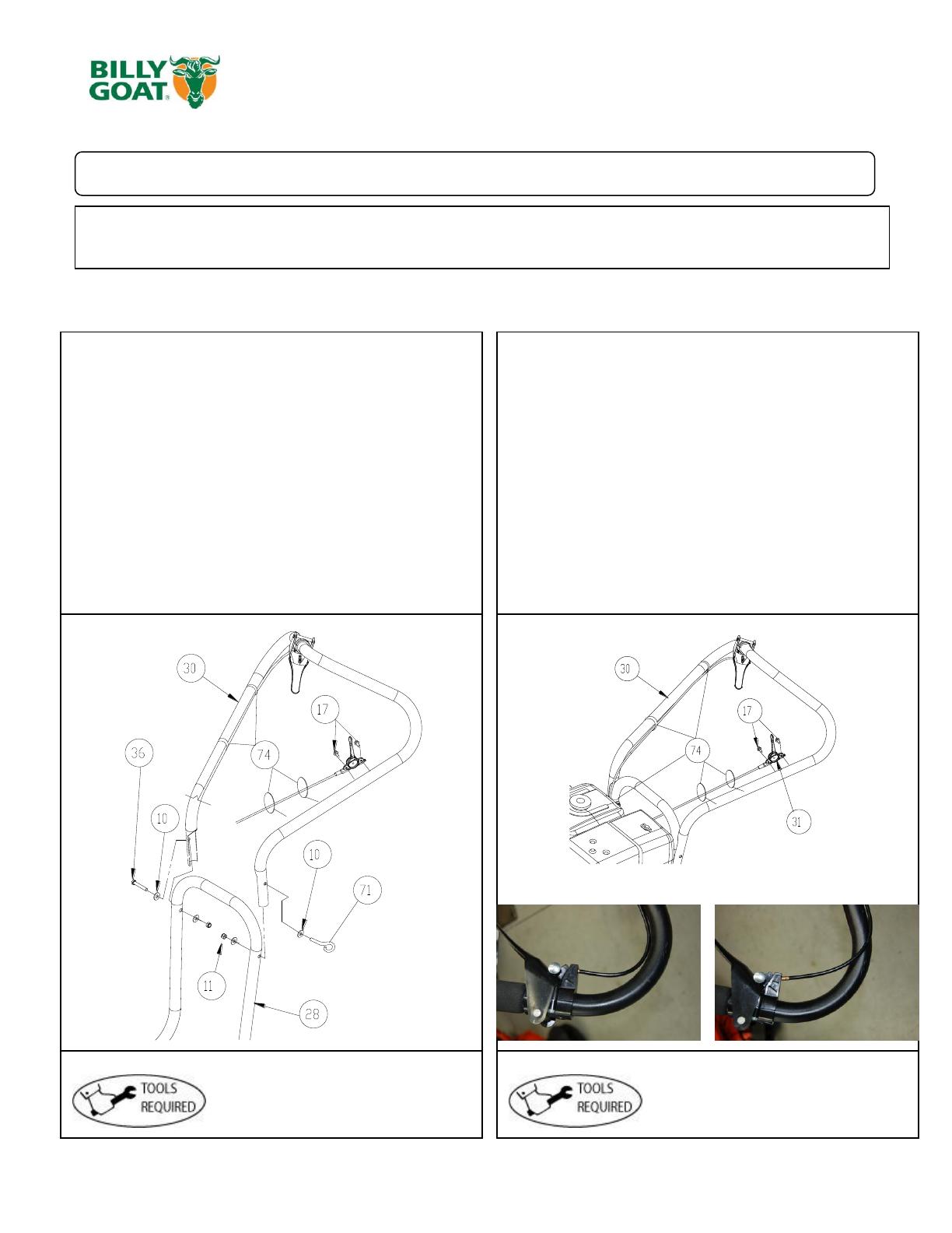
10 WASHER 5/16 FLATWASHER Z/P 8171003 20 8171003 20 8171003 20 8171003 20
11 NYLON INSERT LOCKNUT 5/16-18 8160002 10 8160002 10 8160002 10 8160002 10
12 SCREWCAP 5/16-18 X 1.75 ZP 8041031 4 8041031 4 8041031 4 8041031 2
13 SCREWCAP 1/4-20 x 1 1/2 8041008 11 8041008 11 8041008 11 8041008 11
14 NUT FLANGE 1/4-20 900455 11 900455 11 900455 11 900455 11
15 WHEEL & TIRE 13" X 5" PNEUMATIC 440054 2 440054 2 440054 2 440054 2
16 RING RETAINING 3/4 850230 2 850230 2 850230 2 850230 2
17 SCREW SELF-TAP 5/16 NC X 3/4 HEX 8122082 7 8122082 7 8122082 7 - -
18 WHEEL ASSY 10 " PNEUMATIC 400295 1 400295 1 400295 1 400295 1
19 SPACER FRONT AXLE 440220 1 440220 1 440220 1 440220 1
20 SPACER LH WHEEL FRONT 440224 1 440224 1 440224 1 440224 1
21 SPACER RH WHEEL FRONT 440221 1 440221 1 440221 1 440221 1
22 SCREWCAP 1/2-13 x 9 1/2" 8041240 1 8041240 1 8041240 1 8041240 1
23 WASHER FLAT 1/2" SAE 8172011 2 8172011 2 8172011 2 8172011 2
24 WASHER W/BOLT WA 440075 1 440075 1 440075 1 440075 1
25 KNOB 3/8-16 SOLID HUB 811230 1 811230 1 811230 1 811230 1
26 WASHER 2.25 OD x .515 ID x .134 ZP 610308-P 1 610308-P 1 610308-P 1 610308-P 1
27 BRACKET HOLDER WA 440240 1 440240 1 440240 1 - -
28 HANDLE LOWER 440034 1 440034 1 440034 1 440034 1
29 NYLON INSERT LOCKNUT 1/2-13 8160005 1 8160005 1 8160005 1 8160005 1
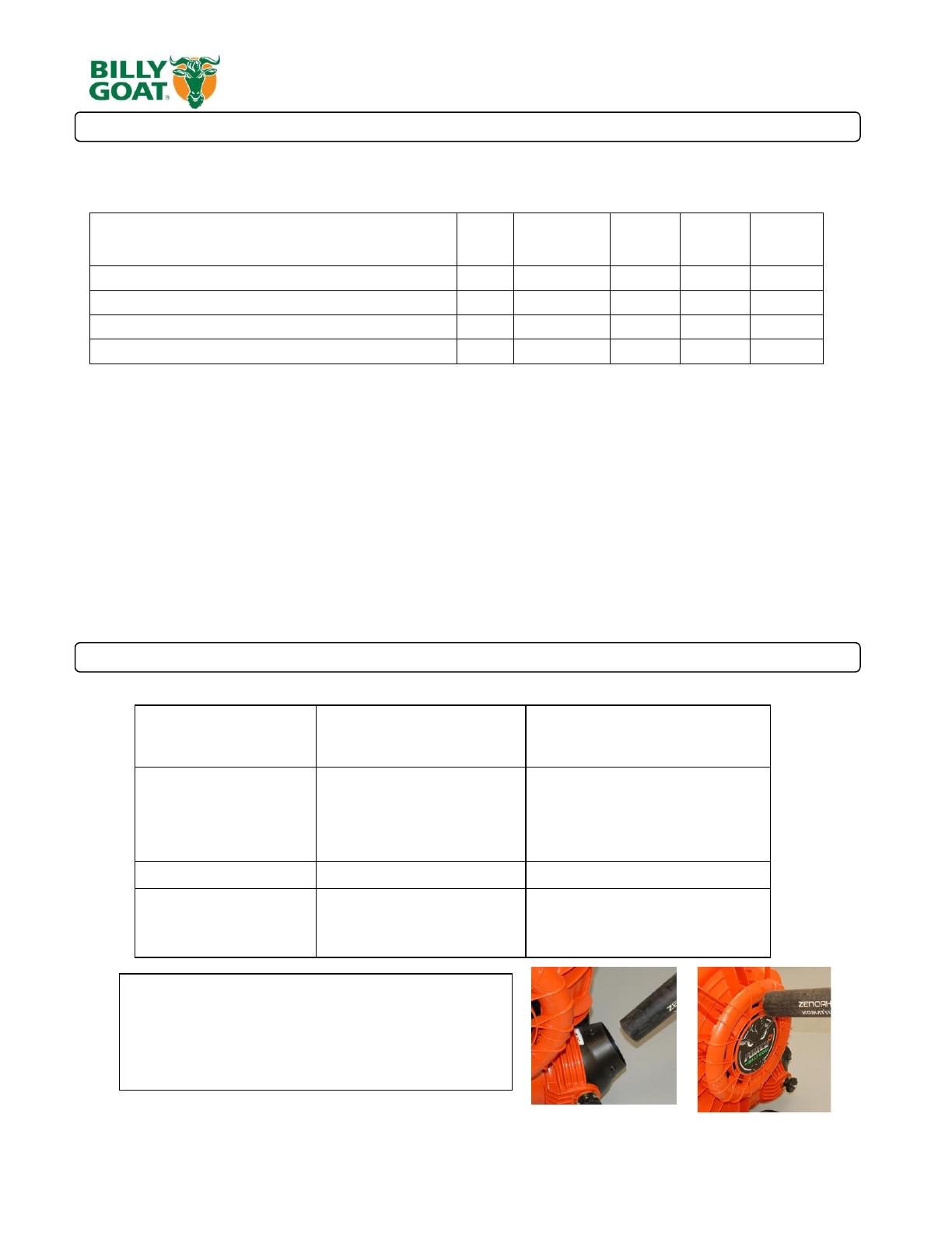
30 HANDLE UPPER 440035 1 440035 1 440035 1 440035 1
31 CONTROL THROTTLE 440013 1 440013 1 440013 1 440013 1
32 CABLE THROTTLE CONTROL 440014 1 440014 1 440014 1 440178 1
33 NUT LOCK 3/8-16 LT WT THIN ZP 8161042 1 8161042 1 8161042 1 8161042 1
34 WASHER 1.5 O.D.X 0.45 I.D. X 0.5 440176 1 440176 1 440176 1 440176 1
35 SCREWCAP 3/8-24 X 2 3/4" GR. 8 (38 +/-2 ft-lbs.) 790167 1 - - - - - -
SCREWCAP 7/16-20 X 2 3/4" GR.8 (60 +/-2 ft-lbs) - - 440285 1 440285 1 - -
SCREWCAP 3/8-24 X 4 GR.8 (38 +/-2 ft-lbs) - - - - - - 8042062 1
36 SCREWCAP 5/16"-18 X 2" ZP 8041032 1 8041032 1 8041032 1 8041032 2
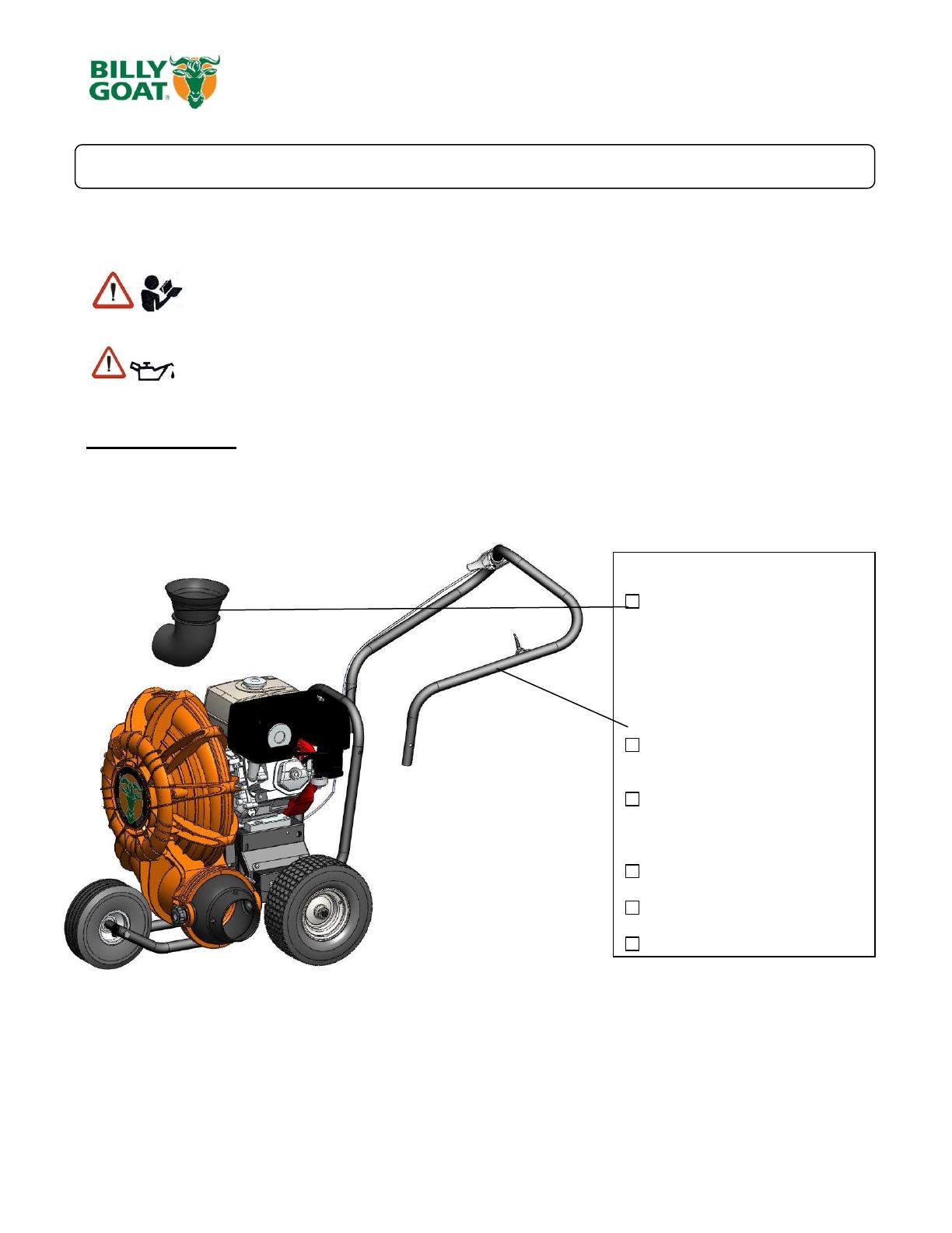
37 DIRECTOR CONE 5" 440044-S 1 - - - - - -
DIRECTOR CONE 4" - - 440046-S 1 440046-S 1 - -
DIRECTOR CONE 6" - - - - - - 440170-S 1
38 DIVERTOR FRONT 440045-5 1 440045-4 1 440045-4 1 - -
39 SCREW SM #10-24X1/2" DRILL POINT 8122064 2 8122064 2 8122064 2 8122064 2
40 IMPELLER ASSEMBLY 17" 440236 1 440236 1 440236 1 - -
IMPELLER SERVICE ASSY FORCE 18HP - - - - - - 440162 1
41 GRILL FRONT BLOWER 440067-1-S 1 440067-1-S 1 440067-1-S 1 440171-S 1
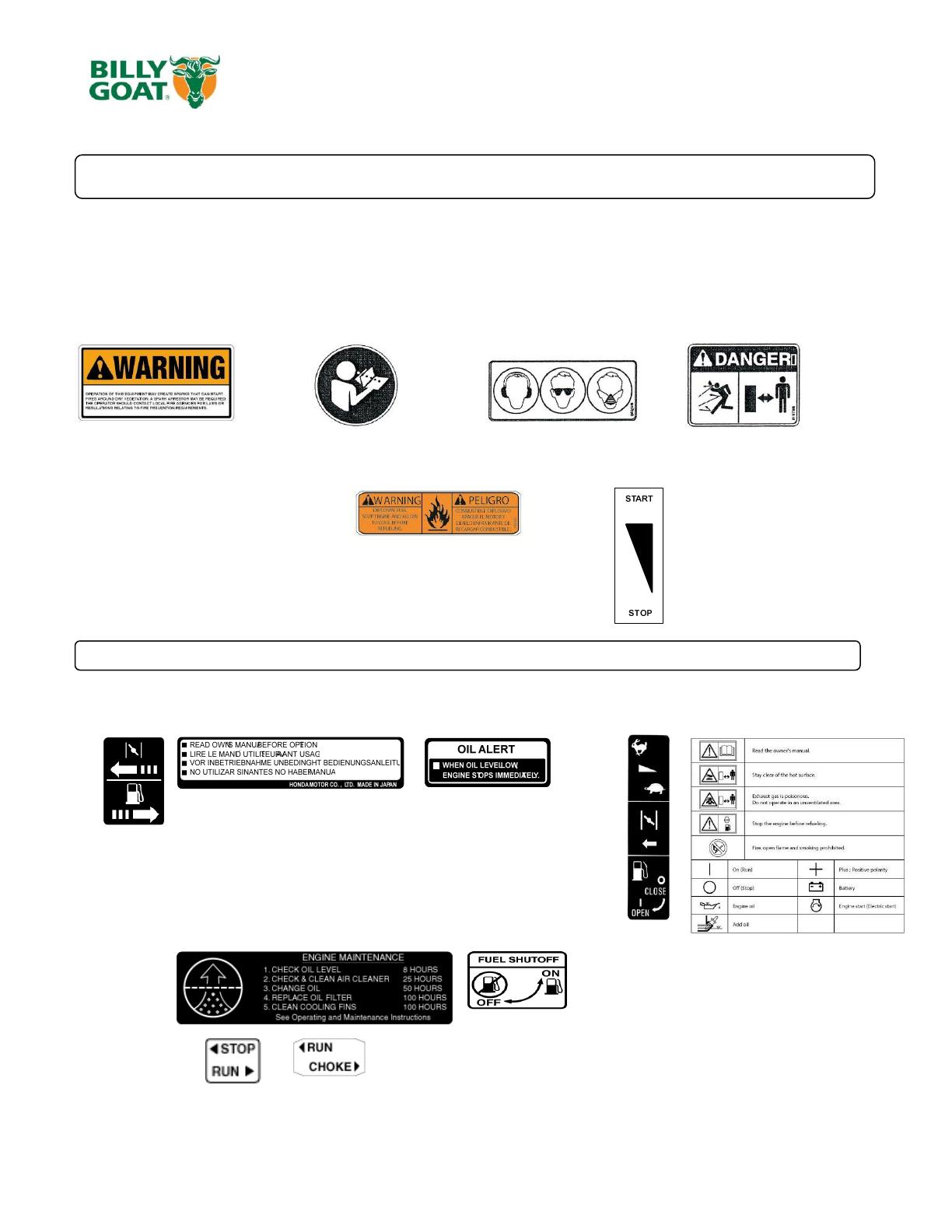
42 LABEL THROTTLE CONTROL 810656 1 810656 1 810656 1 810656 1
43 LABEL FUEL EN/SP - - - - 100261 1 100261 1
44 LABEL READ 890301 1 890301 1 890301 1 890301 1
45 LABEL EAR EYE BREATHING 890254 1 890254 1 890254 1 890254 1
46 LABEL DANGER FLYING DEBRIS 810736 1 810736 1 810736 1 810736 1
47 GRIP 1-1/4" ID x 13" 440012 1 440012 1 440012 1 440012 1
48 LABEL FORCE 440268 1 440268 1 440268 1 440268 1
49 HANDLE ASSY UPPER 440104 1 440104 1 440104 1 440104 1
50 KEY 1/4" SQ x 3.25 9201128 1 9201128 1 9201128 1 - -
KEY 1/4" SQ x 2.75 - - - - - - 9201130 1
51 SCREWCAP 1/4-20 X 1" - - - - - - 8041006 7
52 WASHER FLAT 1/4 - - - - - - 8171002 5
53 NUT LOCK 1/4"-20 HEX ZP 8160001 1 8160001 1 8160001 1 8160001 1
54 HANDLE DIVERTER FORCE 440119 1 440119 1 440119 1 440119 1
55 PIN LATCH DIVERTER 440118 1 440118 1 440118 1 440118 1
56 SPRING COMPRESSION 0.281 X 0.88 440129 1 440129 1 440129 1 440129 1
57 RING RETAINING .122 DIA 440125 1 440125 1 440125 1 440125 1
58 SADDLE LOWER DIVERTER 440115 1 440115 1 440115 1 440115 1
59 PLATE LOCK DIVERTER 440116 1 440116 1 440116 1 440116 1
60 SCREW PLASTITE #6-19 X 5/8" 440126 1 440126 1 440126 1 440126 1
Not for Reproduction
Part No 440313 Form No F110612A
11
FORCE BLOWER PUSH Owner’s Manual
F1301H/F1402S F901H F901S F1801V
ITEM NO. DESCRIPTION PART NUMBER QTY. PART NUMBER QTY. PART NUMBER QTY. PART NUMBER QTY.
61 SADDLE UPPER DIVERTER 440114 1 440114 1 440114 1 440114 1
62 SCREW PLASTITE #10-14 X 1" 440132 2 440132 2 440132 2 440132 2
63 PIN PIVOT DIVERTER CONTROL 440123 1 440123 1 440123 1 440123 1
64 RING RETAINING 5/16 430327 1 430327 1 430327 1 430327 1
65 CABLE ASSY 440117 1 440117 1 440117 1 440117 1
66 DIVERTER PIVOT ADAPTOR 440121 1 440121 1 440121 1 440121 1
67 SPRING EXTENSION 0.468 X 5.25 440130 1 440130 1 440130 1 440130 1
68 BRACKET DIVERTER FORCE 440212 1 440212 1 440212 1 440212 1
69 PIN CLEVIS 1/4 X 3/4 440124 1 440124 1 440124 1 440124 1
70 .051 X 3/4" HITCH PIN CLIP 440193 1 440193 1 440193 1 440193 1
71 EYEBOLT PIGTAIL 5/16"-18 X 1 1/4" 440280 1 440280 1 440280 1 440280 1
72 ADAPTOR MOUNT WA 440122 1 440122 1 440122 1 440122 1
73 GRIP 1-1/4" ID x 9.5" LONG 440146 1 440146 1 440146 1 440146 1
74 TY-WRAP 900407 5 900407 5 900407 5 900407 5
75 WASHER .765 ID X 1.25 OD X 0.6" 850238 2 850238 2 850238 2 850238 2
76 FORCE WHEEL BEARING .751 ID 440055 2 440055 2 440055 2 440055 2
77 GUARD MANIFOLD - - - - - - 812243 1
78 GUARD MUFFLER - - - - - - 812242 1
79 SPACER 1" ID X 2" OD X 0.890 TK - - - - - - 830112 1
80 SPACER 1" ID X 2" OD X 0.265 TK - - - - - - 830113 2
81 SCREW SELF TAP 1/4"-20 X 5/8" - - - - - - 890359 2
82 SPACER REAR WHEEL PUSH 440226 2 440226 2 440226 2 440226 2
83 PLUG 791056 2 791056 2 791056 2 791056 2
84 CARRIAGE BOLT 3/8"-16 X 2" ZP 8024062 4 8024062 4 8024062 4 8024062 4
85 SPARK ARRESTOR LABEL 100252 1 100252 1 100252 1 100252 1
86 WASHER LOCK 3/8 ST MED 8177012 1 - - - - 8177012 1
WASHER LOCK 7/16 ST MED - - 8177013 8177013 1 - -
87 SCREW PLASTITE 1/4"-10 X 3/4" HWH ZP 840082 2 840082 2 840082 2 840082 2
88 BOLT 1/4"-20 X 1/2" SER FLANGE - - - - - - 812381 2
125 LABEL MADE IN U.S.A. 520116 1 520116 1 520116 1 520116 1
Not for Reproduction
  • Page 1 1
  • Page 2 2
  • Page 3 3
  • Page 4 4
  • Page 5 5
  • Page 6 6
  • Page 7 7
  • Page 8 8
  • Page 9 9
  • Page 10 10
  • Page 11 11

Billy Goat BLOWER, BILLY GOAT User manual

Category
Air blowers/dryers
Type
User manual
This manual is also suitable for

Ask a question and I''ll find the answer in the document

Finding information in a document is now easier with AI