Peavey CD Mix 9072A Professional DJ Mixer Owner's manual
- Category
- Audio mixers
- Type
- Owner's manual


CD
MIXm
9072A
CAUTION: Do not use spray cleaner for any slide control as this will wash out vital
lubricants and shorten component life.
A
#ithin
the product’~
A
Intended to alert
the
~iwr
of the
pl-esence
01‘
important
operating
and maintenance
(wwicing)
in\truc*tions in
the
liteI2tuI-e
mxmpanyin~
the
lmxluct.
CAUTION: Risk of clcxtl-ical shock
-
DO NOT OPEN!
CAUTION:
To
~-cx~uce
the
I-isk
of electric
dmch,
do
not
1-e11wvt’
COVCI-.
No
UWI-
WI-\
iceablc
part\
inside.
Rcl.cr
w-\/icing
to
qualified sewice
pcIwnnc1.
WARNIN
appliance.
thi4
appl iancc
to rain of nioi~tnrc.
Bcf‘oi-c
using
(Iii\
Please read this entire manual before hooking the mixer into your audio system.
A
Estc
\imbolo
tiene
el
propci\ito
dc
;Ilcrtx
al usuario
de
la
prcwncia
clc
‘I(\
olt:I.je)
pcIi~ro\o”
clue
no
ticnc
aislaniiento
dcntro
tic
la
caja
dcl
prod~icto
qiie
piicdt’ tent3
una
nla~nitud
sut‘icicntc
coriio
p;i~-a
~~rm4tituir
I-ic4go
dc
corricnta70.
A
Este
simbolo
ticnc
el
pIxq’ci\ito
de
alertar
aI
uwrio
de
la
pwwncia
de instrucconc~ importante~
\ob~-c
Ia
olw;IcitiIl
y
mantt’nimicnto
cn
la
littmtura
cj~it’
L
icnc
con
~1
producto.
PRECACJCION: Ricsgo
de
corricntwo
-
No
ah-a.
PRECAUCION:
Pal-a
di~minuir
cl
I-iesyo
dc
corrientwo.
no
ahra la cubierta. No hay
pic/;I\
adc‘ntro
clue
cl
u\;Irio
pL~cda
reparar. Deje todo
mantcnimicnto
;I
10s
t6cnicw
calil‘icado4.
ADVERTENCIA
Antes
de
usx
cste
no
dejc
c\puc~to
;I
Ia
Iluvid
0
IIuIIIccIxI
c\tc
itin.
A
Cc
syniholc
c5t
utiliQ
pur
inclicluer
II
I’utili4;itcur
la
p1-6sc1icc
ii
I’iIitCI-icur
de
cc‘
procluit
dc
tcn\ioIi
nowiv)lGc
daiigere~iw
poii\
ant
:(I-t
d’inttzn\itt!
\uf‘t‘i\;Intc
polii-
con4tituer
LIII
riwluc
clc
clioc
ClcctI‘icluc.
A
Ce
\ymbolc
est
utiliG
pour
indicluci-
II
I’utili~atcur
clu’il
011 clu’cllc
ti-~~ii\c13
d’iiIIl~oI~t;iIit~~
in~tructioii~
\iII‘
l’utilisation
et
l’cntretien
(eI.\zice)
de
I’app’;II’~iI
dani
la
IittGI-alure
~IccoIlll,a~II~IIIt
Ic
pixduit.
ATTENTION: Risque\
dc
CIIOC
dlcctricluc
-
NE PAS OllVRll~v
ATTENTION: At’in
dc
I-&luiI-c
Ic
rique
de
choc Clcctriquc. IlC
I-xl’
CIIIC\
Cl‘
Ic
COlI\
crclc.
II
IIC’
\c‘
tr~oir\~c
;I
I’intCi~icuI~
aLicLinc
piece
poiivmt
Cti-c
rCp;lrC;c
par I’utilisateur.
Cont‘iei-
I’cntrcticii
iI
IIn perv~nncl clu;IIiI‘ii‘.
AVERTISSE:MENT:
At‘in
clc
011 Il
l’humiditt?. A\,ant
cl’ut
de d~charge 6Icctricluc
ou
liw/
le\
;i\~crti~wnicnt
I :I
Ia
pluic
le
yuidc.
A
Dieses
Symbol
wll
den
Anc~~ncler
\‘or
uni\olicrtcn
gci‘iibi-lichen
.Sl~;~nnun~c~i
iniicrlialb
cIc4
(;cIi;iuw\
\v;irIIcII.
die
van
Ausrcichender
Stlirhc sind.
LIIII
cincn
clektri\chcn
Schlas
vcru~.~;Ic‘hcn
/II
hiinIIcI1.
A
Diews
Symbol
sol1
den
Bcnutxr
auf
uicbtigc
Instruhtioncn
in
clcr
Bedicn~In~~~InIcitIII1~ aul’IIIcI~hwIl~
111x-hen.
die
Handhabung
LIII~
Wartung
de\
Produht~ betret‘ten.
VORSICHT: Risiho
-
Elehtrischcr
Schlag!
Nicht
iit‘i’nen!
VORSICHT: Urn
clas
Ri\iko
eine$
elchtriwhen
Schla~es
J,LI
vermeidcn.
nicht
clic
Abdcchunc
cnl~crnc~l.
f:s
bcl‘irdcu
\icll
keine Teilc &u-in, die vom Anwcndtzr repariert
wt’~‘dc‘n
hiinnten.
Reparaturen nur van ~l~I;IIiI.i,it’I.tuIll
f;:IcIIpcrv)II;II
duI-cbfiihwn
laswn.
ACHTUNG: Urn einen elektrische II Schlq
oder
Fe~w@‘ahr
/LI
1
erniciden.
\olltc
dicsc$
GcI-lit
Fcuchtigkeit ausgesetzt
weden.
VW
Inbetriebnahnw
unbedingt
die Bcdi~nun~s~InleitLin~
lcwn.
nicht
dciii
f<cgcn
0dc1-
2

Parts Inventory
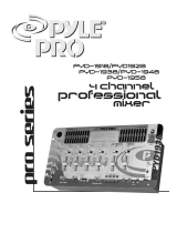
Thank you for purchasing the Peavey CD MIX 9072 A professional DJ mixing unit.
When used in accordance with this manual, your new DJ mixer will give years of good
service.
In order to read this manual you will have already unpacked the unit.
You should have:
One CD MIX 9072 A mixer unit.
One 16 V AC UL listed wall-mount power supply unit.
(This is packaged separately.)
Please retain the packing material for future use.
Features:
l Monitor facility with separate switch for mic in/out
l CD/phone switches on all three phono music inputs
l 4-way assignable Crossfade switches
l Seven music inputs
l Selectable program effects loop to add echo, reverb etc. or more graphic EQ
l Separate, selectable, Mic effects loop common to both mic inputs
l
7-band
graphic EQ
+
12
dB
on each band; 30 mm slide pots fitted with center-
detent for easy zeroing of EQ
l
EQ select switch
l Two front-panel-mounted Low-Z Mic inputs
-
ideal for rap
DJs
who often
work in groups of two or more people
l Individually-selectable headphone cueing for each music
channel.
l Twin, crossfade-assignable beat lights for pre-matching dance music tempos
before crossfading
l Selectable automatic voice-over
l Manual push-to-talk voice-over button
l Cuing selector to listen to stereo program output, stereo channel cuing, or
channel cue in right
earcup
and program out put in left
earcup.
l Individually adjustable levels for program and channel cueing facilities
l Built-in gooseneck XLR light socket
l 45 mm heavy-duty crossfade slider
l 3-band EQ for both
mics
completely independent of the program graphic EQ.
Changes made to the program EQ don’t affect your mic EQ and vice versa
l Power on/off switch with LED indicator
l High slew-rate super low-noise op amps are used throughout the entire
mixer’s circuitry
l 60 mm high-quality studio slide faders are used on all channels and master
level control
l Available in 115 v 60 Hz and 220-240 v 50 Hz versions
l Two monitor and program outputs giving extra program outputs for different
dance areas as well as providing audio inputs for lighting equipment
l Full easy-to-read stereo metering switchable for Program or Cue

General Description:
The CD
MIXTM9072A
multi-media entertainment mixer is a brand new addition to
Peavey’s line of premium quality DJ equipment.
It is an all-American-made, high-quality, rugged, professional DJ mixer.
DJs,
rap recording artists, and specialist DJ equipment dealers were closely involved
in active consultancy throughout each design stage.
Housed in a 1
O-1/2”
x 19” super slim-line (only
l-3/4”
deep) rugged steel chassis, the
CD
MIXTM
9072A boasts a truly remarkable array of much-preferred DJ features,
including: three individual music channels; seven music inputs, three of these inputs
being individually switchable to phono or CD; fully assignable crossfade; seven-band
audio EQ; and built-in gooseneck XLR light socket . All slider potentiometers are
studio-quality
Alps@
components.
The two low-impedance, phantom-powered, front-panel-mounted microphone inputs
deliver fast, positive connect and disconnect facility for the
DJ’s
mic. Many other DJ
mixers have the mic socket mounted on the rear of the mixer chassis so the mixer has
to be physically lifted out of the console to work with the mic connection.
Because CDs are playing a much larger part as the preferred DJ music medium, and
vinyl is becoming very difficult to obtain, each phono input on this DJ mixer has an
individual slide switch that changes the input from vinyl to CD (or back again) quickly
and easily. Therefore, as vinyl becomes even more scarce, every phono (record deck)
input may also be used for CD players. This method of vinyl/CD selection is unique to
the Peavey line of DJ mixers.
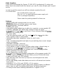
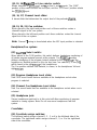
FRONT PANEL
PROGRAM EQUALIZER
MADE IN U.S.A.
LOW
z
MIC
2
6
Q
IN
OUT
MID
.O.
*
.
.
a
0
. .
15
15+
LOW
AUTOMATIC
VOICE OVER
0
ON
OFF
80
ON
OFF
9
lo-
-
9-
-
il
6-
-
,e
e!!!!!!
--
11
l-
-
o-
-
18
ME
““Kk
““tn
7
27
0,
BEAT
ASSIGN
Mic Channel:
26
12-
-
-
62
z
z
---
O-
t’r
---
(j-
-
-
-
12:
z
-
---
---
l
---
--
-
l-l-
---
---
T
---
---
--
--
--
-
-
tl
--
--
--
--
--
63
160 400
1K
25K 6 3K
16K
29
co
FtiONO
LINE
2
.
.
139
al
PHONO
:
LINE
3
16
20
d’
CD
PHONO
iINF4
17
12
EQ
6 SELECT
OUTPUT/CUE PEAK LEVEL
~~&:
38
LAMP
1hVAC
ON
FzzFzl
310
LOOP
IN
OUT
32
339
MIC
ON
OFF
34
23
24
27
28
CD
MBX,
9072A
n
ASSIGN
•e~*~~~a*~~*~*~~e~@*~
8
OHM5
@B
25
26
Professional
DJ
Mixer
(1) Balanced low Z microphone inputs:
For use with low impedance microphones or low level sources equipped with
an XLR connector.
ISvolt
phantom power is provided for electret
mics.
(2) Microphone loop select switch:
When the switch is in the out position the microphone loop is bypassed.
4

(3) High
EQ:
An active
tone
control
(shelvi
ng range
&I5
dB)
that varies the high frequency
range.
(4) Mid EQ:
An active tone control (peak/notch
+I
2
dB)
that adjusts the mid frequency
range.
(5) Low EQ:
An active tone control (shelving range
&I
5
dB)
that varies the low frequency
boost or cut.
Note: This EQ governs both microphone inputs but is not routed through the
7-band
graphic EQ. It is therefore easy to have the
7-band
graphic EQ set up for
high-bass-boost without affecting the clarity/tonality of the microphones.
(6) Automatic voice-over switch:
When this switch is in the “on” position, presentation of signals to either of the
two microphone inputs, such as announcements, etc., automatically drops the
level of the music. Placing this switch in the “off” position defeats this automatic
facility.
(7) Voice-over button:
When pressed, this drops the music level enabling the DJ to talk over the music.
Press to activate and release to inactivate.
(8) Mic on/off switch:
Mic 1 is “live” when the switch is in the ON position.
(9) Microphone 1 Level Slider:
A mono slider that determines the output level of this microphone channel.
Music/Mic
Channels:
(10)
Mic 2 or Line selector switch:
Allows selection between Mic 2 or Line
1
inputs. The “LINE” position of this
switch selects the line input, and the Mic 2 position selects the Mic 2 input.
(11) Channel 1 Level slider:
A stereo slider that determines the output level of channel 1. This is a dual-
function slider, controlling Mic 2 when switch
IO
is in the Mic 2 position and Line
1
when switch
IO
is in the Line
1
position

(12, 13, 14)
Phone/CD
or Line selector switch:
Allows selection of phone/CD (L and
R)
or line (L and
R)
inputs. The “LINE”
position of this switch selects the line input, and the “CD-Phono” position selects
the CD/phone input.
(15, 16, 17) Channel Level slider:
A stereo slider that determines the output
level of the particular
channe
(18, 19, 20, 21) Cue switches:
When placed in the right-hand position each of these switches routes a
channel’s signal to the cue system.
When placed in the left-hand position each these switches routes the channel
signal out of the cue system.
Note: Channel
1
cueing is de-selected when the MIC input position is selected.
Headphone/Cue system:
(22)
Cue/PGM
Select switch:
When placed in the PGM position, this switch delivers headphone monitoring of
all stereo program material present at the outputs. The
PGM/Cue
position
delivers monitoring of the program (output) material to the left earcup of the
headphones. Material present on the cue bus (see Cue switches [I 2 thru
141)
will be heard in the right earcup of the headphones.
The Cue position delivers cue material, in stereo, to the headphones’ left and
right
earcups.
(23) Program Headphone Level slider:
Sets PGM sound levels that are available at the headphone socket when
program is selected.
(24) Channel Cue Headphone Level slider:
Sets Cue sound levels that are available at the headphone socket when cue is
selected.
(25) Headphone jack:
Stereo headphones patched in at this point will allow monitoring of program
material or cueing system. Note: Do not use mono headphones with this
system.
Crossfader:
(26) Crossfade assign switches:
The left-hand switch assigns channel 1, 2 , 3, or 4 to the left-hand side of the
crossfader. The right-hand switch assigns channel 1, 2, or 3 to the right-hand
side of the crossfader.
6

(27) Beat
LEDs:
There is an LED positioned to the side of each crossfade assign switch. These
LEDs
monitor the beat of, and show music activity from, the particular music
channel assigned to each side of the crossfader. They enable beat-matching to
be carried out visually.
(28) Crossfade slider:
A stereo slider which delivers crossfade capability between channels 1, 2 , 3, or
4 according to the position of the two crossfade assign switches.
Blending and crossfading between all channels is accessible by assigning
channels 1, 2 , 3, or 4 for left- and right-hand positioning of the crossfade slider.
For example:
Left-hand ASSIGN switch set to channel
#3
will access channel 3 when the
crossfade slider is in the left-hand position.
Right-hand ASSIGN switch set to channel
#2
will access channel 2 when the
crossfade slider is in the right-hand position.
NOTE: It is useful to remember that when the crossfade slider is set to its center
(number 5) position both channels assigned to the left- and right-hand
crossfade positions will be at equal levels. You may then simply use the
channel level controls to crossfade between the two assigned channels and
ignore the crossfade, leaving it set in the center position. This is a more
“European” technique of crossfading and is preferred by some
DJs.
(29)
7-band
EQ:
Used to boost or cut seven selected frequency bands according to the
placement of the seven slide potentiometers.
(30)
EQ
in/out switch:
When the switch is in the out position the
7-band
EQ
is bypassed.
(31) Program loop
When the switch is in
in/out
switch:
the out
position the
program loop
is
bypassed.
(32) Program Master level:
A stereo slider that determines the overall program level from music channels 1,
2, 3, 4, and the microphone channel.
(33) Mic-to-monitor on/off switch:
When the switch is in the off position the microphones’ signals are not fed
through the monitor system. This is to enable in-booth program material to be
played and cued without feedback from the booth microphones.
When the switch is in the on position the microphones’ signals are fed through
the monitor system. In this way the monitor facility can be used to set the levels
for a second music zone, e.g. a second dance floor or background level for
another zone, instead of being used for monitoring in the DJ booth.

(34) Monitor Master level:
A stereo slider that determines the overall monitor level from channels 1, 2, 3, 4,
and the microphone channel.
(35) LED arrays (left and right):
Two calibrated, LED arrays are provided to visually indicate program output
levels.
(36) Meter select switch:
The cue position of this switch places the stereo LED array on the output of the
cue system. The PGM position places the stereo LED array on the program
output.
(37) Power switch:
Depress to the “On” position to turn the unit on.
(38) Lamp:
A
2-pin
XLR jack is provided for connecting an optional gooseneck mixer lamp
for illumination in adverse lighting conditions. Peavey accessory lamp number
ML-3 is a suitable gooseneck mixer lamp for this purpose.
4
MONITOR/LIGHTING
PROGRAM PROGRAM
OUTPUTS OUTPUTS LOOP
16VAC
165VAC
’
AMP
q
0
@
@
--EFT-
@
@
&
&
@
@
--n1GG-
@
@
@
@
46 45 43
CHANNEL 4 CHANNEL 3
0
44
nh
CD MIX,,, 9072A
l
mmmmmmmmmmmmmmmmo*~e
Professional DJ Mixer
CHANNEL 2 CHANNEL 1
A PRODUCT OF PEAVEY ELECTRONICS CORP MERIDIAN, MS
MADE IN U.S.A.
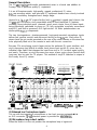
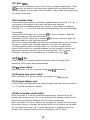
REAR PANEL
Channel Inputs:
(39) Line inputs:
Left and right inputs are provided for “line level” signals from tape decks, CDs,
or other sources. See also (12, 13, 14)
PHONO/LINE
selector switch.

(40)
CD/Phone
inputs:
Left and right inputs are provided for output from turntables or CDs, depending
on position of the CD/Phone switch
(41)
on each channel. See also
(12, 13, 14)
Phone/Line selector switch.
(41)
CD/Phone
switch:
Selects the CD/Phone inputs to accept input from either a magnetic phono
cartridge (Phono [switch down] position) or a compact disk or other line source
(CD [switch up] position).
(42) Mic Loop
-
send and return:
Send and return jacks are provided for mono patching of external effects
devices, graphic equalizers, or other signal processing devices at the
microphone channel.
(43) Program Loop
-
send and return:
Send and return jacks are provided for stereo patching of external effects
devices, graphic equalizers, or other signal processing devices to the program
and monitor channels.
(44) Chassis ground lug:
Grounds from other pieces of equipment should be connected at this point to
minimize ground loop possibilities between power amps, outboard signal
processing units, turntables, etc.
Program outputs:
(45) Program outputs:
Two main output left and right jacks are provided for the main (program) output.
The outputs at this point should be patched out to the stereo power amplifiers
driving the main speaker system. The second pair of outputs may be used to
drive lighting controllers or for tape recording if required.
(46) Monitor outputs:
Two main output left and right jacks are provided for monitoring purposes. The
outputs at this point should be patched out to the stereo power amplifiers driving
the monitor speaker system.
Note: It is often useful to use the monitor outputs to drive an independent
sound system for another audio zone such as a second dance floor or
background music elsewhere within the venue.
The second pair of monitor outputs may also be used to drive lighting
controllers or for tape recording if required.

Power input:
(47) AC Input:
External 16.5 Volt,
1
amp power supply should be plugged in at this point.
Plug the small jack at the end of the power supply lead into the 16 VAC socket
on the rear of the unit (47). Then plug the power supply provided with your
CD MIX 9072A into a main AC wall power receptacle.
CAUTION: Use only the power supply that is provided with this product. If the
original power supply must be replaced, consult your dealer or the factory for
assistance in obtaining the correct replacement. Failure to use the correct
power supply could result in fire or shock hazard, extensive circuit damage,
decreased performance, or non-operation.
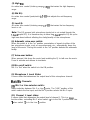
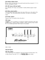
+20dB
I
I
I
IIIIII
I
I I
IIIIII
1
I
I
]
+10dB
OdB
-lOdB
-20dB
20 Hz
50
100
200
500
lk
2k Sk
10k 20k 40k
EQ Frequency and Gain Characteristics
10

_
MIC
LOOP
IN
POWER
LO MID HI
EOtJ%IZER
MIC 1
RUT0
ON
VOX
POWER
MIC 2
MONITOR
MONITOR
L
OUTPUTS
CROSSFADER
MRSTER
EP SELECT
POWER
AMP
OUTPUTS
BEAT
METER SELECT
.
PGM/CUE
0 PGM
CD MlXn.
9072A
•m~m~~em~~me~*om~mee*
Professional DJ Mixer
I

CD
MIXTM
9072A
SPECIFICATIONS:
SUMMARY OF FUNCTIONS:
7 Stereo inputs
-
3 CD/phone and 4 line
4-way assignable crossfade
1 Microphone mixing bus with manual music over-ride switch, 3-band EQ, and
automatic voice-over facility with on/off switch
1 O-segment LED ladders
Switchable stereo headphone jack
15 V phantom power for electret
mics
7-band
program EQ
&I2
dB
45 mm stereo crossfade slider
One 12 VAC mixer lamp socket
MICROPHONE AND CHANNEL 1 FUNCTIONS:
Two low Z balanced microphone inputs with phantom power
3-band
EQ
Automatic voice-over switch
Manual voice-over button
Mic On/Off switch (Mic
I)
Mic/Line switch (Mic 2)
60 mm stereo level sliders
Effects loop in/out switch
Cue switch for Line input
CHANNELS 2-4 FUNCTIONS (Each Channel):
Stereo (RIAA) phono input switchable to CD
Stereo line input
CD/phone selector switch
Stereo selector switch for line input or CD/phone input
60 mm stereo level slider
Independent cue switch for each channel
MASTER SECTION:
7-band graphic equalizer
Stereo
1
O-segment LED display
60 mm stereo program level slider
MONITOR SECTION:
Mic On/Off switch
60 mm stereo monitor level slider
CUE SECTION:
Cue Headphone level
Program Headphone level
Cue/Program Headphone selector switch
12

CD/PHONO
INPUTS:
Phono position:
Input Sensitivity: -50
dB
(3
mV)
Input Impedance: 47K ohms
Max Input Level
@
1
kHz:
-20
dBV
(100
mV)
CD position:
Input Sensitivity: -10
dB
(.316
Volts)
Input Impedance: 47K ohms
Max Input Level:
+I8
dBV
(8 Volts)
LINE
INPUTS:
Input Sensitivity: -10
dB
(.316
Volts)
Input Impedance:
8.3K
ohms
Max Input Level:
+I8
dBV
(8 Volts)
MICROPHONE
INPUTS
(LOW-Z):
Input Sensitivity: -70
dB
(.3
mV)
Input Impedance: 3K ohms
Max Input Level:
+6
dBV
(2 Volts)
MICROPHONE
TALKOVER:
Attenuation (voice-over switch enabled or automatic voice-over enabled):
12dB
FREQUENCY
RESPONSE:
Phono Inputs
(RIAA):
+O/-3
dB
(20 Hz to 20
kHz)
Line Inputs:
+O/-3
dB
(20 Hz to 20
kHz)
Headphone:
+O/-3
dB
(40 Hz to 20
kHz)
SIGNAL-TO-NOISE
RATIOS:
Phono:
>
70
dB
Line:
>
90
dB
DISTORTION:
Less than .Ol%
EQUALIZATION:
63 . .
+12dBat63Hz
-
160:
*I2
dB
at
160
Hz
400:
&I2
dB
at 400 Hz
1
K:
+12dBatl
kHz
2.5K:
+I 2
dB
at 2.5
kHz
6.3K:
+I 2
dB
at 6.3
kHz
16K:
U2dBat
16
kHz
MICROPHONE
EQ:
Low:
+I5
dB
at 50 Hz
Mid:
+I2
dB
at 600 Hz
.
HI
:
+_15dBatlOkHz
13

MAX OUTPUT LEVEL:
+
15.5
dBV
(6 Volts)
POWER REQUIREMENTS:
16.5 VAC, 1000 ma external power supply
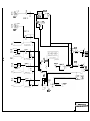
Installing the unit:
This mixer may be mounted in a standard 19” equipment rack using 19”
rack-
mounting screws and washers (Peavey accessory part #5003), or may be built into the
surface of a DJ console by cutting a hole 16.75” x 10.5” and using screws to secure the
unit. See diagram below for dimensions.
I
------
IQ
‘JF;“.
s
-
7
-
-
-
-
-
-
-
---
t
1
I
I
.
A
mm
.
I
I
IO
5”
I
1
I
m
1
I
I
I
.
tl
1
I
--
1
--
~~~~---~~~~
m
46.75”~‘25!-
-
-
-
-
-
-
-
-
-
-
---------------------------
I
---B-B-
------
l-
------s-v---m
CUTOUT
I
SHADED
PORTION
I
m-----s--
----
A-C,L------------
I
C/L
~~~~---I_-----
L
_c_c-m-----w---
I
I
1 device to each pair of outputs
-7
Power Amp.
lY(l
Loudspeakers.
OR
OR
-1
Lighting controller
I
-1
I
I
4
-.
I
I
I
1
3.75
11
-1
I
?
I
1
I
I 3.75
II
-8,
I
-v.
I
-m
Mono
lines
lrom
mrre
phones
CHANNEL 4
CHANNEL 3 CHANNEL 2
CHANNEL
1
CD MIX 9072 A PATCH DIAGRAM 0
ALL LINES ARE STEREO UNLESS NOTED
P

IMPORTANT SAFETY INSTRUCTIONS
WARNING: When using electric products, basic cautions should always be followed, including the following.
Read all safety and operating instructions before using this product.
All safety and operating instructions should be retained for future reference.
Obey all cautions in the operating instructions and on the back of the unit.
All operating instructions should be followed.
2.
3.
5.
6.
This product should not be used near water,
i.e.,
a bathtub, sink, swimming pool, wet basement, etc.
This product should be located so that its position does not interfere with its proper ventilation. It should not be placed flat against a
wall or placed in a built-in enclosure that will impede the flow of cooling air.
This product should not be placed near a source of heat such as a stove, radiator, or another heat producing amplifier.
Connect only to a power supply of the type marked on the unit adjacent to the power supply cord.
7.
8.
9.
Ne
ver break off
the ground pin on the
Hazard and Grounding.”
power
suPPlY
cord. For more information on
grounding,
write for our free booklet “Shock
10.
Power supply cords should always be handled carefully. Never walk or place equipment on power
suppl
cords for cuts or signs of stress, especially at the plug and the point where the cord exits the unit.
y cords. Periodically
check
11.
The power supply cord should be unplugged when the unit is to be unused for long periods of time.
If this product is to be mounted in an equipment rack, rear support should be provided.
12.
13.
Metal parts can be cleaned with a damp rag. The vinyl covering
used on some units can be cleaned
based household cleaner if necessary. Disconnect unit from power supply before cleaning.
with a damp rag or an ammonia-
14.
Care should be
openings.
taken so that objects do not fall and liquids are not spilled into the unit through the ventilation holes or any other
15.
This unit should be checked by a qualified service technician if:
a.
The power supply cord or plug has been damaged.
b.
Anything has fallen or been spilled into the unit.
C.
The unit does not operate correctly.
d.
The unit has been dropped or the enclosure damaged.
16.
The user should not attempt to service this equipment. All service work should be done by a qualified service technician.
This product should be used only with a cart or stand that is recommended by Peavey Electronics.
Exposure to extremely high noise levels may cause a permanent hearing loss. Indiv
iduals vary
considerably in susceptibility
to noise
induced hearing loss, but nearly everyone will lose some hearing if exposed to
sufficiently intense noise for a sufficient time.
17.
18.
U.S. Government
exposures.
Occupational Safety and
Health Administration (OSHA) has specified the following permissible noise level
Duration Per Day In Hours
8
6
Sound Level
dBA,
90
92
95
97
100
102
105
110
115
Slow R.esponse
4
3
2
1 l/2
l/2
l/4 or less
According to OSHA, any exposure in excess of the above permissible limits could result in some hearing loss. Ear plugs or protectors in
the ear canals or over the ears must be worn when operating this amplification system in order to prevent a permanent hearing loss if
exposure is in excess of the limits as set forth above. To ensure against potentially dangerous exposure to high sound pressure levels, it is
recommended that all persons exposed to equipment capable of producing high sound pressure levels such as this amplification system be
protected by hearing protectors while this unit is in operation.
SAVE THESE INSTRUCTIONS!
15

THIS LIMITED WARRANTY VALID ONLY WHEN PURCHASED AND REGISTERED IN THE UNITED STATES OR CANADA. ALL EXPORTED PRODUCTS ARE SUBJECT
TO WARRANTY AND SERVICES TO BE SPECIFIED AND PROVIDED BY THE AUTHORIZED DISTRIBUTOR FOR EACH COUNTRY.
Ces clauses de garantie ne sont vaiables qu’aux Etats-Unis et au Canada. Dans tour les autres pays, les clauses de garantie et de maintenance sont fixees par
le
distributeur national et assuree par
lul
seion la legislation envigueur.
Diese Garantie ist nur in den USA and Kanada gultig. Alle Export-Produkte sind der Garantie und dem Service des lmporteurs des jewelligen Landes unterworfen. Esta
garantia es valida solamente cuando el
product0
es
comprado
en E.U. continentales o en Canada. Todos
10s
productos que Sean comprados en
el
extranjero, estan
sujetos a las garantias y servicio que
cada
distribuidor autorizado determine y ofrezca en
10s
diferentes paises.
PEAVEY ONE-YEAR LIMITED
WARRANTY/REMEDY
PEAVEY ELECTRONICS CORPORATION (“PEAVEY”) warrants this product, EXCEPT for covers,
footswitches,
patchcords, tubes and meters, to be free from defects
In
matenal and workmanshrp for a period of one (1) year from date of purchase. PROVIDED, however, that
thus
lImIted warranty IS extended only to the original retail purchaser and
is subject to the conditions, exclusions, and limitations hereinafter set forth,
PEAVEY
90-DAY
LIMITED WARRANTY ON TUBES AND METERS
If this product contains tubes or meters Peavey warrants the tubes or meters contained
In
the product to be free from defects
In
material and workmanshrp for a penod of ninety
(90) days from date of purchase; PROVIDED. however, that this limited warranty IS extended only to the ongrnal retail purchaser and is also subject to the conditrons,
exclusions,
and limitations hereinafter set forth
CONDITIONS, EXCLUSIONS, AND LIMITATIONS OF LIMITED WARRANTIES
These limited warranttes shall be void and of no effect
if.
a.
The first purchase of the product is for the purpose of resale, or
b.
The original retail purchase IS not made from an AUTHORIZED PEAVEY DEALER; or
c.
The product has been damaged by accident or unreasonable use, neglect, improper service or maintenance, or other causes not ansing out of defects
In
material or workmanship,
or
d.
The serial number affixed to the product is altered. defaced, or removed.
In the event of a defect
in
material and/or workmanship covered by this limited warranty, Peavey will
a.
In the case of tubes or meters replace the defective component
without
charge
b.
In other covered cases (i.e., cases involving anything other than covers, footswitches, patchcords, tubes or meters), repair the defect
In
material or workmanship or replace the
product, at Peavey’s option, and provrded, however, that, in any case, all costs of shrpping, if necessary, are paid by you, the purchaser.
THE WARRANTY REGISTRATION CARD SHOULD BE ACCURATELY COMPLETED AND MAILED TO AND RECEIVED BY PEAVEY WITHIN FOURTEEN (14) DAYS FROM
THE DATE OF YOUR PURCHASE.
In order to obtain service under these warranties, you must:
a.
Bring the defective item to any PEAVEY AUTHORIZED DEALER or AUTHORIZED PEAVEY SERVICE CENTER and present therewith the ORIGINAL PROOF OF PURCHASE
supplied to you by the AUTHORIZED PEAVEY DEALER in connection with your purchase from him of this product. If the DEALER or SERVICE CENTER IS unable to provrde
the necessary warranty service you will be directed to the nearest other PEAVEY AUTHORIZED DEALER or AUTHORIZED PEAVEY SERVICE CENTER which can provide
such service.
OR
b.
Ship the defective Item, prepaid, to:
PEAVEY ELECTRONICS CORPORATION
International Service Center
326 Hwy. 11
&
80 East
MERIDIAN, MS 39301
Including therewith a complete, detailed description of the problem, together with a legible copy of the original PROOF OF PURCHASE and a complete return address. Upon
Peavey’s receipt of these items
If the defect is remedral under these limited warranties and the othertermsand
conditions
expressed herein have been complied with, Peavey will provide the necessary warranty
service to repair or replace the product and will return
It,
FREIGHT COLLECT, to you, the purchaser.
Peavey’s liability to the purchaser for damages from any cause whatsoever and regardless of the form of action, including negligence, IS limited to the actual damages up to
the greater of $500.00 or an amount equal to the purchase pnce of the product that caused the damage or that IS the subject of or is directly related to the cause of action. Such
purchase price will be that in effect for the specific product when the cause of action arose. This limitation of
liabrlrty
will not apply to claims for personal injury or damage to real property
or tangible personal property allegedly caused by Peavey’s negligence Peavey does not assume liability for personal Injury or property damage arising out of or caused by a non-
Peavey alteration or attachment, nor does Peavey assume any responsbrlrty for damage to interconnected non-Peavey equipment that may result from the normal functioning and
maintenance of the Peavey equipment.
UNDER NO CIRCUMSTANCES WILL PEAVEY BE LIABLE FOR ANY LOST PROFITS, LOST SAVINGS. ANY INCIDENTAL DAMAGES, OR ANY CONSEQUENTIAL
DAMAGES ARISING OUT OF THE USE OR INABILITY TO USE THE PRODUCT, EVEN IF PEAVEY HAS BEEN ADVISED OF THE POSSIBILITY OF SUCH DAMAGES.
THESE LIMITED WARRANTIES ARE IN LIEU OF ANY AND ALL WARRANTIES, EXPRESSED OR IMPLIED, INCLUDING, BUT NOT LIMITED TO, THE IMPLIED
WARRANTIES OF MERCHANTABILITY AND FITNESS FOR A PARTICULAR USE, PROVIDED, HOWEVER, THAT IF THE OTHER TERMS AND CONDITIONS NECESSARY
TO THE EXISTENCE OF THE EXPRESSED, LIMITED WARRANTIES, AS HEREINABOVE STATED, HAVE BEEN COMPLIED WITH, IMPLIED WARRANTIES ARE NOT
DISCLAIMED DURING THE APPLICABLE ONE-YEAR OR NINETY-DAY PERIOD FROM DATE OF PURCHASE OF THIS PRODUCT.
SOME STATES DO NOT ALLOW LIMITATION ON HOW LONG AN IMPLIED WARRANTY LASTS, OR THE EXCLUSION OR LIMITATION OF INCIDENTAL OR
CONSEQUENTIAL DAMAGES, SO THE ABOVE LIMITATIONS OR EXCLUSIONS MAY NOT APPLY TO YOU THESE LIMITED WARRANTIES GIVE YOU SPECIFIC LEGAL
RIGHTS, AND YOU MAY ALSO HAVE OTHER RIGHTS WHICH MAY VARY FROM STATE TO STATE.
THESE LIMITED WARRANTIES ARE THE ONLY EXPRESSED WARRANTIES ON
-1
‘; PRODUCT, AND NO OTHER STATEMENT, REPRESENTATION, WARRANTY,
OR AGREEMENT BY ANY PERSON SHALL BE VALID OR BINDING UPON PEAVEY.
In the event of any modification or disclaimer of expressed or implied warranties, or any limitation of remedies, contained herein conflicts with applicable law, then such
modification, disclaimer or limitation, as the case may be, shall be deemed to be modified to the extent necessary to comply with such law.
Your remedies for breach of these warranties are limited to those remedies provided herein and Peavey Electronics Corporation
gives
this
lrmrted
warranty only with respect
to equipment purchased in the United States of America.
INSTRUCTIONS -WARRANTY REGISTRATION CARD
1.
Mail the completed WARRANTY REGISTRATION CARD to:
PEAVEY ELECTRONICS CORPORATION
POST OFFICE BOX 2898
MERIDIAN, MISSISSIPPI 39302-2898
a.
Keep the PROOF OF PURCHASE. In the event warranty service is required during the warranty period, you will need this document. There will be no rdentrfrcatron card issued
by Peavey Electronics Corporation.
2.
IMPORTANCE OF WARRANTY REGISTRATION CARDS AND NOTIFICATION OF CHANGES OF ADDRESSES:
a.
Completion and mailing of WARRANTY REGISTRATION CARDS-Should notification become necessaryforanycondition that may requirecorrection, the REGISTRATION
CARD will help ensure that you are contacted and properly notified.
b.
Notice of address changes
-
If you move from the address shown on the WARRANTY REGISTRATION CARD, you should notify Peavey of the change of address so as
to facilitate your receipt of any bulletins or other forms of notification which may become necessary in connection with any condition that may require dissemination of
information or correction.
3.
You may contact Peavey directly by telephoning (601) 483-5365.
Features and specifications subject to change without notice.
Peavey Electronics Corporation 711 A Street
/
Meridian, MS 39301
/
U.S.A.
/
(601) 483-5365
/
Telex 504115
/
Fax 486-1278
01994
#80301694
Printed in U.S.A.
1
l/94
-
 1
1
-
 2
2
-
 3
3
-
 4
4
-
 5
5
-
 6
6
-
 7
7
-
 8
8
-
 9
9
-
 10
10
-
 11
11
-
 12
12
-
 13
13
-
 14
14
-
 15
15
-
 16
16


Peavey CD Mix 9072A Professional DJ Mixer Owner's manual
- Category
- Audio mixers
- Type
- Owner's manual
Ask a question and I''ll find the answer in the document
Finding information in a document is now easier with AI
Related papers
-
Peavey Production Mixer 1000 System Non-Powered DJ Mixer Owner's manual
-
-
-
-
-
-
-
-
-
Other documents
-
Klip Xtreme KSH-300 Datasheet
-
PYLE Audio PYD1939 User manual
-
 PYLE Audio PYD-1918 User manual
-
 PYLE Audio PYD1955 User manual
-
Pyramid Stereo System PM 1008 User manual
-
Vestax PMC-46MKII Owner's manual
-
Peavey Electronics BTS 2.2 Black Specification
-
Yorkville Sound YS1010 User manual
-
 PYLE Audio PYD-710 User manual
-
Gemini PS-828X Owner's manual


