
INSTALLATION
MANUAL
DOOR STATION N-8050DS
Designed to connect to the IP Intercom Exchange, the N-
8050DS is a door station featuring high quality hands-free
conversation and has a contact output (momentarily closed)
to remotely control an electronic door lock.
Using with an electrical box or surface mounting box, the
station can be mounted to a wall.
The N-8050DS is in full conformity with IP44 water-proof
and dust-proof standards. The operating temperature range
is –10 to +50°C.
As provided with guard nets inside to cover over the
openings of microphone and speaker, the N-8050DS can be
installed free from care in public space.
2. WALL MOUNTING
1. GENERAL DESCRIPTION
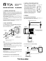
2.1. Mounting to a 3-gang Switch Box (with cover)
Mount the N-8050DS to electrical
boxes mounted in the wall.
Notes
• The wall should be over 12 mm thick, and the opening in
the wall for an electrical box should be under 115 mm
(wide) by 162 mm (high).
• When using for electronic door lock control, fix the N-
8050DS with tamper-proof screws such as "Torx" screws
to prevent it from being easily removed.
2.2. Mounting to the YS-13A Wall Mount Box
Install the YS-13A on a wall and mount the station in the
same way as 2.1.
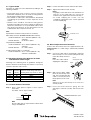
4. WIRING
4.1. Connection to the Exchange
4.2. Connection to an External Relay
Connect the Exchange to the station's LINE terminals via
the E-7000TB Terminal Board as illustrated.
E-7000TB
Terminal board
Mini-clamp connector
(Supplied with the N-8000EX)
Twisted pair cable
N-8000EX/8010EX Exchange
16 lines
N-8050DS (rear panel)
LINE H C
Both upper and lower
terminals (clip terminals)
are internally connected.
N-8050DS
Wall
surface
Oval head combination screw
M4 x 25 (accessory)
3-gang electrical box
YC-150 (optional)
The N-8050DS comes with 2 types of screws: oval head
combination screw M4 x 25 and oval head slotted screw
UNC No.6 x 18.
For the electrical box provided with unified threads, use the
oval head slotted screws UNC No.6 x 18.
Accessory screws
Open collector output: 30 V DC, 50 mA
External
power supply
Relay
Diode
N-8000EX/8010EX Exchange
+24 V DC
GND
+
-
N-8050DS (Rear panel)
LINE H C
3. INSTALLATION PRECAUTIONS
• When installing the N-8050DS
outdoors or at locations where it gets
wet with water, tightly seal the panel
edges. Besides, provide a weep hole
at the underside of the mounting box
to permit water to drain off.
• When installing the N-8050DS under
difficult environmental conditions
such as in coastal areas or at humid
locations, cover the inside of the N-
8050DS with coating. For the coating
method, consult your TOA dealer.
Seal the panel edges.
N-8050DS's
front panel

4.3. Type of Cable
The types of cables are to be determined according to the
following conditions.
• Twisted pair wires (such as those used for electronic
push-button telephone) are to be used for wiring between
the Exchange and the stations in principle.
• The number of cables pairs laid should be determined
considering the possibility of future expansion of the
system.
• Outdoor wires should be used where wiring passes
through inaccessible areas such as ceilings or under floors
where the maintenance is not performed. Indoor wires
may also be used, however, in case where there is no risk
of deterioration due to exposure to heat, etc.
Note
Specifications related to each junction are as follows.
Mini-clamp connector (N-8000EX/8010EX line terminal)
Conductor diameter: ø0.4 – 0.65 mm (AWG22 – 26),
solid wire
Outside diameter: ø1.05 mm or below
Clip terminal (E-7000TB)
Conductor diameter: ø0.4 – 0.8 mm (AWG20 – 26),
solid wire
Outside diameter: ø1.5 mm or below
Terminal station (LINE, H, C terminals)
Conductor diameter: ø0.4 – 1.3 mm (AWG16 – 26),
solid wire, stranded wire
4.5. Terminal Station Connection
Step 1. Strip a cable jacket of approx 7 mm to expose
inner cable.
For cables, refer to Type of Cable.
Note
Do not solder plate on exposed inner cables when
using a stranded wire.
Step 2. Loosen the terminal screws and insert the cables.
Step 3. Tighten the terminal screws securely.
Notes
• Tug lightly on the cable to be sure that it does not
pull free. If the cable pulls free, loosen the
terminal screw again and reconnect from Step 2.
• To avoid stripping the screws, use the
screwdriver appropriate to the screws tightened
into the terminal plug.
4.4. Relations Between Core Diameter of Cable
and Maximum Cable Length
Referring to the following chart as guidelines, design the
distance between the Exchange and stations so that loop
resistance becomes 170 Ω or less.
4.6. Mini-clamp Connector Connection
Connect the mini-clamp connector supplied with the N-
8000EX/8010EX to a cable using a commercially available
tool (pliers).
Step 1. Cut off two-cable ends in equal length, and insert
them securely to a cover section (transparent side)
of the mini-clamp connector.
Note
Insert the cable without
stripping the cable jacket.
Step 2. With a pair of pliers, lightly
pinch the mini-clamp cover
and, after ensuring that the
cable is securely inserted,
firmly squeeze on the cover.
Note
Squeeze on the mini-clamp cover until it is
correctly locked.
Step 3. Insert the wired connector (plug) into the
exchange's connector (socket) until it locks into
place.
Cover
(transparent side)
Cable
N-8000EX/8010EX Rear panel
Conductor Loop Maximum cable length
diameter resistance between the Exchange and station.
(mm) (Ω/ km)
(Assuming that the loop resistance is 170 Ω.)
ø0.4 295 570 m
ø0.5 187 900 m
ø0.65 113 1.5 km
ø0.9 58 2.9 km
Printed in Japan
133-06-264-1B
7 mm
Tighten
Terminal screw
Cable
-
 1
1
-
 2
2


TOA Q-N8050WP User manual
- Type
- User manual
- This manual is also suitable for
Ask a question and I''ll find the answer in the document
Finding information in a document is now easier with AI
Related papers
Other documents
-
Optimus N-8050DSWP User manual
-
Aiphone AN-8050DSW Supplemental Instructions
-
-
-
-
-
-
-
MiTAC 8050D User manual
-