
Serial Number
Decal
Model No. PFTL49612.0
Serial No.
Write the serial number in the space
above for reference.
CAUTION
Read all precautions and instruc-
tions in this manual before using
this equipment. Save this manual
for future reference.
QUESTIONS?
If you have questions, or if parts
are damaged or missing, DO NOT
CONTACT THE STORE; please
contact Customer Care.
IMPORTANT: Please register this
product (see the limited warranty
on the back cover of this manual)
before contacting Customer Care.
CALL TOLL-FREE:
1-888-533-1333
Mon.–Fri. 6 a.m.–6 p.m. MT
Sat. 8 a.m.–4 p.m. MT
ON THE WEB:
www.proformservice.com
USER’S MANUAL
www.proform.com

2
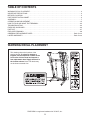
WARNING DECAL PLACEMENT . . . . . . . . . . . . . . . . . . . . . . . . . . . . . . . . . . . . . . . . . . . . . . . . . . . . . . . . . . . . . . .2
IMPORTANT PRECAUTIONS ..................................................................3
BEFORE YOU BEGIN. . . . . . . . . . . . . . . . . . . . . . . . . . . . . . . . . . . . . . . . . . . . . . . . . . . . . . . . . . . . . . . . . . . . . . . .5
PART IDENTIFICATION CHART. . . . . . . . . . . . . . . . . . . . . . . . . . . . . . . . . . . . . . . . . . . . . . . . . . . . . . . . . . . . . . . .6
ASSEMBLY . . . . . . . . . . . . . . . . . . . . . . . . . . . . . . . . . . . . . . . . . . . . . . . . . . . . . . . . . . . . . . . . . . . . . . . . . . . . . . . .7
OPERATION AND ADJUSTMENT .............................................................15
HOW TO FOLD AND MOVE THE TREADMILL . . . . . . . . . . . . . . . . . . . . . . . . . . . . . . . . . . . . . . . . . . . . . . . . . . .22
TROUBLESHOOTING ......................................................................23
EXERCISE GUIDELINES ....................................................................26
PART LIST. . . . . . . . . . . . . . . . . . . . . . . . . . . . . . . . . . . . . . . . . . . . . . . . . . . . . . . . . . . . . . . . . . . . . . . . . . . . . . . .27
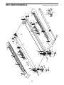
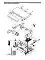
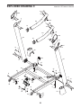
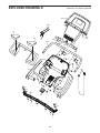
EXPLODED DRAWING. . . . . . . . . . . . . . . . . . . . . . . . . . . . . . . . . . . . . . . . . . . . . . . . . . . . . . . . . . . . . . . . . . . . . .28
ORDERING REPLACEMENT PARTS. . . . . . . . . . . . . . . . . . . . . . . . . . . . . . . . . . . . . . . . . . . . . . . . . . . Back Cover
LIMITED WARRANTY. . . . . . . . . . . . . . . . . . . . . . . . . . . . . . . . . . . . . . . . . . . . . . . . . . . . . . . . . . . . . . . Back Cover
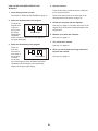
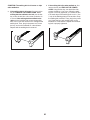
This drawing shows the locations of the
warning decals. If a decal is missing or
illegible, call the telephone number on the
front cover of this manual and request a
free replacement decal. Apply the decal in
the location shown. Note: The decals may
not be shown at actual size.
WARNING DECAL PLACEMENT
256836
PROFORM is a registered trademark of ICON IP, Inc.
TABLE OF CONTENTS

3
1. It is the responsibility of the owner to ensure
that all users of this treadmill are adequately
informed of all warnings and precautions.
2. Before beginning any exercise program,
consult your physician. This is especially
important for persons over age 35 or persons
with pre-existing health problems.
3. Use the treadmill only as described in this
manual.
4. The treadmill is intended for home use only.
Do not use the treadmill in any commercial,
rental, or institutional setting.
5. Keep the treadmill indoors, away from mois-
ture and dust. Do not put the treadmill in a
garage or covered patio, or near water.
6. Place the treadmill on a level surface, with
at least 8 ft. (2.4 m) of clearance behind it
and 2 ft. (0.6 m) on each side. Do not place
the treadmill on any surface that blocks air
openings. To protect the floor or carpet from
damage, place a mat under the treadmill.
7. Do not operate the treadmill where aerosol
products are used or where oxygen is being
administered.
8. Keep children under age 12 and pets away
from the treadmill at all times.
9. The treadmill should be used only by per-
sons weighing 300 lbs. (136 kg) or less.
10. Never allow more than one person on the
treadmill at a time.
11. Wear appropriate exercise clothes while
using the treadmill. Do not wear loose
clothes that could become caught in the
treadmill. Athletic support clothes are recom-
mended for both men and women. Always
wear athletic shoes. Never use the treadmill
with bare feet, wearing only stockings, or in
sandals.
12. Plug the power cord into a surge suppressor
(not included), and plug the surge suppres-
sor into an appropriate outlet (see page 15).
To avoid overloading the circuit, do not plug
other electrical devices, except for low-power
devices such as cell phone chargers, into
the surge suppressor or into an outlet on the
same circuit.
13. Use only a surge suppressor that meets all of
the specifications described on page 15. To
purchase a surge suppressor, see your local
PROFORM dealer, call the telephone number
on the front cover of this manual, or see your
local electronics store.
14. Failure to use a properly functioning surge
suppressor could result in damage to the
control system of the treadmill. If the control
system is damaged, the walking belt may
slow, accelerate, or stop unexpectedly, which
may result in a fall and serious injury.
15. Keep the power cord and the surge suppres-
sor away from heated surfaces.
16. Never move the walking belt while the power
is turned off. Do not operate the treadmill
if the power cord or plug is damaged, or if
the treadmill is not working properly. (See
TROUBLESHOOTING on page 23 if the tread-
mill is not working properly.)
17. Read, understand, and test the emergency
stop procedure before using the treadmill
(see HOW TO TURN ON THE POWER on
page 17).
18. Never start the treadmill while you are stand-
ing on the walking belt. Always hold the
handrails while using the treadmill.
19. The treadmill is capable of high speeds.
Adjust the speed in small increments to
avoid sudden jumps in speed.
20. The heart rate monitor is not a medical
device. Various factors, including the user’s
WARNING: To reduce the risk of burns, fire, electric shock, or injury to persons, read
all important precautions and instructions in this manual and all warnings on your treadmill before
using your treadmill. ICON assumes no responsibility for personal injury or property damage sus-
tained by or through the use of this product.
IMPORTANT PRECAUTIONS

4
movement, may affect the accuracy of heart
rate readings. The heart rate monitor is
intended only as an exercise aid in determin-
ing heart rate trends in general.
21. Never leave the treadmill unattended while
it is running. Always remove the key, press
the power switch into the off position (see
the drawing on page 5 for the location of the
power switch), and unplug the power cord
when the treadmill is not in use.
22. Do not attempt to move the treadmill until it
is properly assembled. (See ASSEMBLY on
page 7, and HOW TO FOLD AND MOVE THE
TREADMILL on page 22.) You must be able
to safely lift 45 lbs. (20 kg) to raise, lower, or
move the treadmill.
23. When folding or moving the treadmill, make
sure that the storage latch is holding the
frame securely in the storage position.
24. Never insert any object into any opening on
the treadmill.
25. Inspect and properly tighten all parts of the
treadmill regularly.
26. DANGER: Always unplug the power
cord immediately after use, before clean-
ing the treadmill, and before performing the
maintenance and adjustment procedures
described in this manual. Never remove the
motor hood unless instructed to do so by an
authorized service representative. Servicing
other than the procedures in this manual
should be performed by an authorized ser-
vice representative only.
27. Over exercising may result in serious injury
or death. If you feel faint or if you experience
pain while exercising, stop immediately and
cool down.
SAVE THESE INSTRUCTIONS

5
Thank you for selecting the new PROFORM
®
425
CT treadmill. The 425 CT treadmill offers an impres-
sive selection of features designed to make your
workouts at home more enjoyable and effective. And
when you’re not exercising, the unique treadmill can
be folded up, requiring less than half the oor space of
other treadmills.
For your benet, read this manual carefully before
using the treadmill. If you have questions after
reading this manual, please see the front cover of this
manual. To help us assist you, please note the product
model number and serial number before contacting us.
The model number and the location of the serial num-
ber decal are shown on the front cover of this manual.
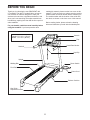
Before reading further, please review the drawing
below and familiarize yourself with the labeled parts.
BEFORE YOU BEGIN
Handrail
Upright
Tray
Key/Clip
Power Switch
Walking Belt
Platform Cushion
Foot Rail
Power Cord
Idler Roller
Adjustment Screws
Console
Heart Rate Monitor
Length: 5 ft. 10 in. (178 cm)
Width: 2 ft. 10 in. (86 cm)

6
#8 x 1/2" Ground
Screw (3)–1
Base Foot
Spacer (94)–2
#8 x 3/4" Screw
(1)–10
3/8" Star
Washer (11)–6
1/4" Star
Washer (34)–2
#8 x 1/2" Screw
(2)–6
#8 x 1" Tek Screw
(5)–4
3/8" Nut (10)–5
5/16" Star
Washer (13)–2
#10 x 3/4" Screw
(2)–4
3/8" x 4" Screw (7)–4
5/16" x 1"
Bolt (4)–2
1/4" x 1"
Screw (9)–4
3/8" x 1 3/4" Bolt (6)–1
3/8" x 2" Bolt (8)–5
5/16" x 1"
Screw (3)–4
3/8" x 1 1/2" Screw (14)–2
#10 Star
Washer (12)–4
1/4" x 1/2"
Bolt (9)–4
1/4" Star
Washer (34)–4
#8 x 1" Screw
(53)–4
#10 Star
Washer (12)–4
PART IDENTIFICATION CHART
Use the drawings below to identify small parts used for assembly. The number in parentheses below each draw-
ing is the key number of the part, from the PART LIST near the end of this manual. The number following the key
number is the quantity used for assembly. Note: If a part is not in the hardware kit, check to see if it is preat-
tached. Extra parts may be included.

7
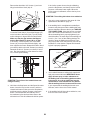
1. Make sure that the power cord is unplugged.
With the help of a second person, carefully tip
the treadmill onto its left side. Partially fold the
Frame (55) so that the treadmill is more stable;
do not fully fold the Frame yet.
Cut the shipping tie securing the Upright Wire
(87) to the Base (95). Next, locate a plastic tie in
the indicated hole in the Base, and use the tie to
pull the Upright Wire out of the hole.
Attach two Base Feet (90) to the Base (95) in the
locations shown with two #8 x 1" Tek Screws (5)
and two Base Foot Spacers (94).
Then, attach the other two Base Feet (90) with
two #8 x 1" Tek Screws (5).
1
95
5
55
90
90
5
5
5
90
94
90
87
Hole
94
ASSEMBLY
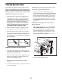
• To hire an authorized service technician to
assemble the treadmill, call 1-800-445-2480.
• Assembly requires two persons.
• Place all parts in a cleared area and remove the
packing materials. Do not dispose of the packing
materials until you nish all assembly steps.
• After shipping, there may be an oily substance
on the exterior of the treadmill. This is normal. If
there is an oily substance on the treadmill, wipe
it off with a soft cloth and a mild, non-abrasive
cleaner.
• Left parts are marked “L” or “Left” and right parts
are marked “R” or “Right.”
• To identify small parts, see page 6.
• Assembly requires the following tools:
the included hex key
one Phillips screwdriver
one adjustable wrench
needlenose pliers
scissors
To avoid damaging parts, do not use power tools.

8
3. Identify the Right Upright (85). Hold the Right
Upright near the Base (95) as shown.
See the inset drawing. Tie the wire tie in the
Right Upright (85) securely around the end of the
Upright Wire (87). Then, pull the other end of the
wire tie until the Upright Wire is routed through
the Right Upright.
Wire Tie
87
85
95
3
Wire
Tie
85
87
2. See the inset drawing. Cut the plastic tie near
the Upright Wire (87).
Attach a Wheel (96) to the Base (95) with a 3/8"
x 2" Bolt (8) and a 3/8" Nut (10). Do not over-
tighten the Nut; the Wheel must turn freely.
Then, press a Base Cap (89) into the Base (95).
95
8
10
2
96
89
Plastic Tie
Cut
87
87

9
4. Hold the Right Upright (85) against the Base
(95). Be careful not to pinch the Upright
Wire (87). Insert two 3/8" x 4" Screws (7) with
two 3/8" Star Washers (11) and a 3/8" x 1 1/2"
Screw (14) with a 3/8" Star Washer (11) into the
Right Upright.
Partially tighten the 3/8" x 4" Screws (7) until
the heads of the Screws touch the Right Upright
(85); do not fully tighten the Screws yet. Then,
partially tighten the 3/8" x 1 1/2" Screw (14).
95
85
87
11
11
14
7
4
5. With the help of a second person, lower the
treadmill so that the Base (95) is flat on the floor.
Attach a Wheel (96) to the Base (95) with a 3/8"
x 2" Bolt (8) and a 3/8" Nut (10). Do not over-
tighten the Nut; the Wheel must turn freely.
Press a Base Cap (89) into the Base (95).
5
8
95
10
89
96

10
7. Identify the Right Base Cover (91) and the Left
Base Cover (88). Slide the Right Base Cover
onto the Right Upright (85) as shown. Slide the
Left Base Cover onto the Left Upright (84).
91
85
84
88
7
6. Hold the Left Upright (84) against the Base (95).
Insert two 3/8" x 4" Screws (7) with two 3/8"
Star Washers (11) and a 3/8" x 1 1/2" Screw
(14) with a 3/8" Star Washer (11) into the Left
Upright.
Partially tighten the 3/8" x 4" Screws (7) until the
heads of the Screws touch the Left Upright (84);
do not fully tighten the Screws yet. Partially
tighten the 3/8" x 1 1/2" Screw (14).
6
84
7
95
14
11
11

11
9. Set the console assembly face down on a soft
surface to avoid scratching the console
assembly.
Remove the screws (A) and the two ties (B)
attaching the Crossbar (104). Next, lift off the
Crossbar. Discard the screws and the ties.
9
104
Console
Assembly
A
B
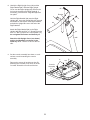
8. Identify the Right Upright Cover (86) and the
Right Handrail (83). Slide the Right Upright
Cover onto the Right Upright (85). Remove the
tie from the bracket on the Right Handrail. If
necessary, press the 5/16" Cage Nut (38) back
into place.
Hold the Right Handrail (83) near the Right
Upright (85). Insert the Upright Wire (87) through
the bracket on the bottom of the Right Handrail,
and pull the Upright Wire out of the end of the
Right Handrail.
Attach the Right Handrail (83) to the Right
Upright (85) with two 5/16" x 1" Screws (3) and a
5/16" x 1" Bolt (4) with a 5/16" Star Washer (13);
do not tighten the Screws and the Bolt yet.
Attach the Left Upright Cover (not shown)
and the Left Handrail (not shown) in the
same way. Note: There is no wire on the left
side.
38
83
Bracket
3
4
13
86
85
87
8
B

12
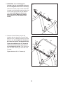
10. IMPORTANT: To avoid damaging the
Crossbar (104), do not use power tools and
do not overtighten the #10 x 3/4" Screws (2).
Orient the Crossbar (104) as shown. Attach the
Crossbar to the Handrails (82, 83) with four #10
x 3/4" Screws (2) and four #10 Star Washers
(12); do not fully tighten the Screws yet.
Note: The #10 Star Washers are slightly
smaller than the 1/4" Star Washers (not
shown).
10
104
12
2
83
82
12
2
11. Insert the Console Frame (102) into the
Handrails (82, 83). Attach the Console Frame
with four 1/4" x 1" Screws (9) and four 1/4" Star
Washers (34); do not tighten the Screws yet.
Be careful not to pinch the Upright Wire (87).
Tighten the indicated #10 x 3/4" Screws (2)
in each end of the Crossbar (104) first; do
not overtighten the Screws. Then, tighten the
other #10 x 3/4" Screws (2) in each end of the
Crossbar.
Tighten the four 1/4" x 1" Screws (9).
11
104
83
102
82
87
34
9
34
9
First
First
2
2

13
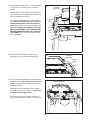
12. Firmly tighten the four 5/16" x 1" Screws (3) and
the two 5/16" x 1" Bolts (4) (only one side is
shown).
With the help of a second person, hold the con-
sole assembly near the Right Handrail (83) and
the Left Handrail (not shown).
Connect the Upright Wire (87) to the console
wire. See the inset drawing. The connectors
should slide together easily and snap into
place. If they do not, turn one connector and try
again. IF YOU DO NOT CONNECT THE CON-
NECTORS PROPERLY, THE CONSOLE MAY
BECOME DAMAGED WHEN YOU TURN ON
THE POWER. Then, remove the wire tie from
the Upright Wire.
14. Set the console assembly on the Left and Right
Handrails (82, 83). Be careful not to pinch any
wires. Insert the excess Upright Wire (87) into
the Right Handrail.
Attach the console assembly to the Crossbar
(104) with six #8 x 3/4" Screws (1). Start all six
Screws, and then tighten them.
Attach the two Console Clamps (105) to the
console assembly with four #8 x 1" Screws (53).
83
105
53
87
1
1
1
Console Assembly
82
104
Console
Assembly
12
Console
Wire
Wire
Tie
83
87
4
3
87
Console
Wire
14
13. Connect the ground wire from the console
assembly to the Console Ground Wire (52).
52
Ground
Wire
13
Console
Assembly

14
15. Hold the Right Upright Cover (86) against the
console assembly. Align the holes in the Right
Upright Cover with the holes in the Right Upright
(85). Attach the Right Upright Cover with two #8
x 3/4" Screws (1).
Attach the Left Upright Cover (80) to the Left
Upright (84) in the same way.
See steps 4 and 6. Tighten the four 3/8" x 4"
Screws (7) and the two 3/8" x 1 1/2" Screws (14).
15
85
84
1
1
Console
Assembly
80
86
17. Make sure that all parts are properly tightened before you use the treadmill. If there are sheets of plastic
on the treadmill decals, remove the plastic. To protect the oor or carpet, place a mat under the treadmill.
Note: Extra parts may be included. Keep the included hex keys in a secure place; one of the hex keys is used
to adjust the walking belt (see pages 24 and 25).
16. Raise the Frame (55) to the position shown.
Have a second person hold the Frame until
this step is completed.
Orient the Storage Latch (51) so that the large
barrel and the latch knob are in the positions
shown.
Attach the Latch Bracket (39) to the Base (95)
with two 3/8" x 2" Bolts (8) and two 3/8"
Nuts (10).
Next, a ttach the upper end of the Storage Latch
(51) to the bracket on the Frame (55) with a 3/8"
x 2" Bolt (8) and a 3/8" Nut (10). Note: It may be
necessary to move the Frame back and forth to
align the Storage Latch with the bracket.
Lower the Frame (55) (see HOW TO LOWER
THE TREADMILL FOR USE on page 22).
16
51
95
10
Large
Barrel
8
55
10
39
8
Latch Knob

15
OPERATION AND ADJUSTMENT
HOW TO CONNECT THE POWER CORD
Use a Surge Suppressor
Your treadmill, like other electronic equipment, can be
damaged by sudden voltage changes in your home’s
power. Voltage surges, spikes, and noise interfer-
ence can result from weather conditions or from other
appliances being turned on or off. To decrease the
risk of damaging the treadmill, always use a surge
suppressor with the treadmill. To purchase a surge
suppressor, see precaution 13 on page 3.
Use only a surge suppressor that is UL 1449 listed as a
transient voltage surge suppressor (TVSS). The surge
suppressor must have a UL suppressed voltage rating
of 400 volts or less and a minimum surge dissipation of
450 joules. The surge suppressor must also be electri-
cally rated for 120 volts AC and 15 amps. There must
be a monitoring light on the surge suppressor to indi-
cate whether it is functioning properly. Failure to use a
properly functioning surge suppressor could result
in damage to the control system of the treadmill
and serious injury to users.
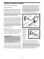
Plug in the Power Cord
The treadmill must be grounded. If it should malfunc-
tion or break down, grounding provides a path of least
resistance for electric current to reduce the risk of elec-
tric shock. The treadmill power cord has a plug with a
grounding pin (see drawing 1 on this page).
Plug the power cord into a surge suppressor, and plug
the surge suppressor into an appropriate outlet that is
properly installed and grounded in accordance with all
local codes and ordinances. The outlet must be on a
nominal 120-volt circuit capable of carrying 15 or
more amps. To avoid overloading the circuit, do
not plug other electrical devices, except for low-
power devices such as cell phone chargers, into
the surge suppressor or into an outlet on the same
circuit. IMPORTANT: The treadmill is not compat-
ible with GFCI-equipped outlets and may not be
compatible with AFCI-equipped outlets.
A temporary
adapter may
be used to
connect the
surge sup-
pressor to
a 2-pole
receptacle
if a properly
grounded
outlet is not
available.
The lug or wire extending from the adapter must
be connected with a metal screw to a permanent
ground such as a properly grounded outlet box cover.
Some 2-pole receptacle outlet box covers are not
grounded. Before using an adapter, contact a quali-
fied electrician to determine whether the outlet box
cover is grounded. The temporary adapter should
be used only until a properly grounded outlet can
be installed by a qualified electrician.
DANGER: Improper connection
of the power cord increases the risk of elec-
tric shock. Do not modify the plug—if it will
not fit an outlet, have a proper outlet installed
by a qualified electrician. If you are unsure
whether the treadmill is properly grounded,
contact a qualified electrician.
1
Surge
Suppressor
Grounding Pin
Grounded Outlet
2
Adapter
2-pole Receptacle
Lug
Grounding Pin
Metal
Screw

16
ETPF49612
(PFTL49612)
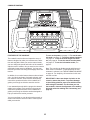
FEATURES OF THE CONSOLE
The treadmill console offers an impressive array of
features designed to make your workouts more effec-
tive and enjoyable. When you use the manual mode,
you can change the speed and incline of the treadmill
with the touch of a button. As you exercise, the console
will display instant exercise feedback. You can even
measure your heart rate using the handgrip heart rate
monitor.
In addition, the console features sixteen onboard work-
outs—six calorie workouts, ve timed workouts, and
ve distance workouts. Each workout automatically
controls the speed and incline of the treadmill as it
guides you through an effective exercise session.
Lose unwanted pounds with the progressive 8-week
weight-loss program. Each workout in the program
controls the speed and incline of the treadmill as it
guides you through an effective workout designed to
help you achieve the results you want.
You can even listen to your favorite workout music or
audio books with the console’s stereo sound system
while you exercise.
To turn on the power, see page 17. To use the man-
ual mode, see page 17. To use an onboard workout,
see page 19. To use an 8-week weight-loss work-
out, see page 20. To use the stereo sound system,
see page 21. To use the information mode, see
page 21.
Note: The console can display speed and distance in
either miles or kilometers. To nd which unit of mea-
surement is selected, see THE INFORMATION MODE
on page 21. For simplicity, all instructions in this man-
ual refer to miles.
IMPORTANT: If there are sheets of plastic on the
console, remove the plastic. To prevent damage
to the walking platform, wear clean athletic shoes
while using the treadmill. The rst time you use
the treadmill, observe the alignment of the walking
belt, and center the walking belt if necessary (see
page 25).
CONSOLE DIAGRAM

17
HOW TO TURN ON THE POWER
IMPORTANT: If the treadmill has been exposed to
cold temperatures, allow it to warm to room tem-
perature before turning on the power. If you do not
do this, you may damage the console displays or
other electrical components.
Plug in the power cord
(see page 15). Next, lo-
cate the power switch on
the treadmill frame near
the power cord. Press the
power switch into the reset
position.
IMPORTANT: The console features a display demo
mode, designed to be used if the treadmill is dis-
played in a store. If the displays light as soon as
you plug in the power cord and press the power
switch into the reset position, the demo mode is
turned on. To turn off the demo mode, hold down
the Stop button for a few seconds. If the displays
remain lit, see THE INFORMATION MODE on page
21 to turn off the demo mode.
Next, stand on the
foot rails of the
treadmill. Find the
clip attached to
the key and slide
the clip onto the
waistband of your
clothes. Then, in-
sert the key into
the console. After a moment, the displays will light.
IMPORTANT: In an emergency, the key can be
pulled from the console, causing the walking belt
to slow to a stop. Test the clip by carefully taking
a few steps backward; if the key is not pulled from
the console, adjust the position of the clip.
HOW TO USE THE MANUAL MODE
1. Insert the key into the console.
See HOW TO TURN ON THE POWER at the left.
2. Select the manual mode.
When the key is inserted, the manual mode will be
selected. If you have selected a workout, press the
Manual button on the console.
3. Start the walking belt.
To start the walking belt, press the Start button, the
Speed increase button, or one of the Quick Speed
buttons numbered 1 through 10.
If you press the Start button or the Speed increase
button, the walking belt will begin to move at 1
mph. As you exercise, change the speed of the
walking belt as desired by pressing the Speed in-
crease and decrease buttons. Each time you press
one of the buttons, the speed setting will change
by 0.1 mph; if you hold down the button, the speed
setting will change more quickly. Note: After you
press the button, it may take a moment for the
walking belt to reach the selected speed setting.
If you press one of the numbered Quick Speed but-
tons, the walking belt will gradually change speed
until it reaches the selected speed setting.
To stop the walking belt, press the Stop button.
The time will begin to ash in the display. To re-
start the walking belt, press the Start button or the
Speed increase button.
4. Change the incline of the treadmill as desired.
To change the incline of the treadmill, press the
Incline increase or decrease button or one of the
numbered Quick Incline buttons. Each time you
press one of the buttons, the treadmill will gradually
adjust to the selected incline setting.
Reset
ETPF49612
(PFTL49612)
Key
Clip

18
5. Follow your progress with the displays.
When the
manual
mode is
selected, the
upper half of
the display
will show a
track that represents 1/4 mile (400 m). As you walk
or run, indicators will appear in succession around
the track until the entire track appears. The track
will then disappear and the indicators will again
begin to appear in succession.
The upper half of the display can also show the
elapsed time, the distance you have walked or
run, the speed of the walking belt, the approximate
number of calories you have burned, your pace in
minutes per mile, and the incline of the treadmill.
Press the Priority Display button repeatedly until
the desired workout information appears.
The lower left corner
of the display will show
the elapsed time, the
distance that you have
walked or run, and
the incline level of
the treadmill. Note: When an onboard workout is
selected, the display will show the time remaining
in the workout instead of the elapsed time.
The lower right corner
of the display will show
the approximate number
of calories you have
burned, the speed of
the walking belt, and
your pace in minutes per mile. The right side of the
display will also show your heart rate when you use
the handgrip heart rate monitor.
To reset the display, press the Stop button, remove
the key, and then reinsert the key.
6. Measure your heart rate if desired.
Before using the handgrip heart rate monitor, re-
move the sheets of plastic from the metal contacts
on the pulse bar. In addition, make sure that your
hands are clean.
To measure your heart rate, stand on the foot
rails and hold the pulse bar with your palms on
the metal contacts for approximately ten seconds;
avoid moving your hands. When your pulse is
detected, a heart symbol in the calorie display
will ash each time your heart beats, one or two
dashes will appear, and then your heart rate will be
shown. For the most accurate heart rate read-
ing, continue to hold the contacts for about 15
seconds.
7. Turn on the fan if desired.
The fan features multiple
speed settings. Press
the fan increase or de-
crease button to select a
fan speed or to turn off
the fan. Note: If the fan
is on when the walking
belt is stopped, the fan
will turn off automatically
after a few
minutes.
8. When you are nished exercising, remove the
key from the console.
Step onto the foot rails, press the Stop button, and
adjust the incline of the treadmill to the lowest
setting. The incline must be at the lowest set-
ting or you may damage the treadmill when you
fold it to the storage position. Next, remove the
key from the console and put it in a secure place.
When you are nished using the treadmill, press
the power switch into the off position and unplug
the power cord. IMPORTANT: If you do not do
this, the treadmill’s electrical components may
wear prematurely.
Contacts
Decrease
Increase
Track

19
HOW TO USE AN ONBOARD WORKOUT
1. Insert the key into the console.
See HOW TO TURN ON THE POWER on page 17.
2. Select an onboard workout.
To select an onboard workout, press the Calorie
button, the Timed button, or the Distance button
repeatedly until the desired workout appears in the
display.
When you select an onboard workout, the maxi-
mum speed setting and the maximum incline set-
ting of the workout will ash in the display for a few
seconds and a prole of the speed settings of the
workout will scroll across the display. If you select
a Calorie workout, the approximate number of calo-
ries you will burn will also appear in the display.
3. Start the workout.
Press the Start button or the Speed increase button
to start the workout. A moment after you press the
button, the treadmill will automatically adjust to the
rst speed and incline settings of the workout. Hold
the handrails and begin walking.
Each workout is divided into one-minute segments.
One speed setting and one incline setting are
programmed for each segment. Note: The same
speed setting and/or incline setting may be pro-
grammed for consecutive segments.
During the
workout, the
prole will
show your
progress.
The ashing
segment of
the prole represents the current segment of the
workout. The height of the ashing segment indi-
cates the speed setting for the current segment.
At the end of each segment, a series of tones will
sound and the next segment of the prole will begin
to ash. If a new speed and/or incline setting is
programmed for the next segment, the new speed
and/or incline setting will appear in the displays for
a few seconds and the treadmill will automatically
adjust to the new speed and/or incline setting.
The workout will continue in this way until the last
segment of the prole ashes in the display and the
last segment ends. The walking belt will then slow
to a stop.
Note: The calorie goal is an estimate of the
number of calories that you will burn during
the workout. The actual number of calories
that you burn will depend on various factors
such as your weight. In addition, if you manu-
ally change the speed or incline of the treadmill
during the workout, the number of calories you
burn will be affected.
If the speed or incline setting is too high or too low
at any time during the workout, you can manu-
ally override the setting by pressing the Speed or
Incline buttons; however, when the next segment
of the workout begins, the treadmill will auto-
matically adjust to the speed and incline set-
tings for the next segment.
To stop the workout at any time, press the Stop
button. The time will begin to ash in the display.
To resume the workout, press the Start button or
the Speed increase button. The walking belt will
begin to move at 1 mph. When the next segment of
the workout begins, the treadmill will automatically
adjust to the speed and incline settings for the next
segment.
4. Follow your progress with the displays.
See step 5 on page 18. The lower left corner of the
display will show the time remaining instead of the
elapsed time.
5. Measure your heart rate if desired.
See step 6 on page 18.
6. Turn on the fan if desired.
See step 7 on page 18.
7. When you are nished exercising, remove the
key from the console.
See step 8 on page 18.
Current Segment

20
HOW TO USE AN 8-WEEK WEIGHT-LOSS
WORKOUT
1. Insert the key into the console.
See HOW TO TURN ON THE POWER on page 17.
2. Select the desired week of the program.
To select the
desired week
of the pro-
gram, press
the Select
Week button
repeatedly
until the number of the desired week appears in
the upper left display.
3. Select the desired day of the program.
There are
three day
workouts for
each week of
the program.
To select
the desired
day of the program, press the Select Day button
repeatedly until the number of the desired day
appears in the upper right display.
4. Start the workout.
Press the Go button, and then press the Start but-
ton to start the workout.
The workout will function in the same way as an
onboard workout (see step 3 on page 19).
5. Follow your progress with the displays.
See step 5 on page 18. The lower left corner of the
display will show the time remaining instead of the
elapsed time.
6. Measure your heart rate if desired.
See step 6 on page 18.
7. Turn on the fan if desired.
See step 7 on page 18.
8. When you are nished exercising, remove the
key from the console.
See step 8 on page 18.
Week Number
Day Number
Page is loading ...
Page is loading ...
Page is loading ...
Page is loading ...
Page is loading ...
Page is loading ...
Page is loading ...
Page is loading ...
Page is loading ...
Page is loading ...
Page is loading ...
Page is loading ...
-
 1
1
-
 2
2
-
 3
3
-
 4
4
-
 5
5
-
 6
6
-
 7
7
-
 8
8
-
 9
9
-
 10
10
-
 11
11
-
 12
12
-
 13
13
-
 14
14
-
 15
15
-
 16
16
-
 17
17
-
 18
18
-
 19
19
-
 20
20
-
 21
21
-
 22
22
-
 23
23
-
 24
24
-
 25
25
-
 26
26
-
 27
27
-
 28
28
-
 29
29
-
 30
30
-
 31
31
-
 32
32


Ask a question and I''ll find the answer in the document
Finding information in a document is now easier with AI
Related papers
-
ProForm 831248531 User manual
-
ProForm PFTL49612.1 User manual
-
ProForm PETL99714 User manual
-
-
Pro-Form PFTL60509.0 User manual
-
-
FreeMotion CT 705 User manual
-
Pro-Form 139.3043 User manual
-
ProForm PETL80914 User manual
-
Other documents
-
-
-
NordicTrack 24988C.0 User manual
-
-
NordicTrack 831.24988.1 User manual
-
-
NordicTrack T 7.0 29822.1 User manual
-
-
-
ProForm T 5.7 Treadmill User manual