
Handling instructions
Bedienungsanleitung
Mode d’emploi
Instruzioni per l’uso
Gebruiksaanwijzing
Instrucciones de manejo
Read through carefully and understand these instructions before use.
Diese Anleitung vor Benutzung des Werkzeugs sorgfältig durchlesen und verstehen.
Lire soigneusement et bien assimiler ces instructions avant usage.
Prima dell’uso leggere attentamente e comprendere queste instruzioni.
Deze gebruiksaanwijzing s.v.p. voor gebruik zorgvuldig doorlezen.
Leer cuidadosamente y comprender estas instrucciones antes del uso.
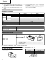
CORDLESS DRIVER DRILL
AKKU-BOHRSCHRAUBER
PERCEUSE-VISSEUSE À BATTERIE
TRAPANO-AVVITATORE A BATTERIA
SNOERLOZE
BOOR-SCHROEFMACHINE
TALADRO ATORNILLADOR
SIN CABLE DE CONEXION
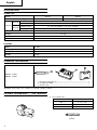
Two speed Variable speed
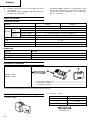
DN 7DT DN 7DV
DN 7DT

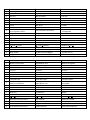
Item
Part Name
No.
1 Flat Hd. Screw (Left Hand) M5 × 17
2A Drill Chuck 10TLRA-N
3 Spindle
4 Ball Bearing (6000VVCMPS2S)
5 Retaining Ring for D10 Shaft
6 Final Gear
7 Metal
8 Motor
9 Internal Wire (B) (Red) 90L
10 Internal Wire (B) (Black) 40L
11 Shift Knob
12 Name Plate
13 Tapping Screw (W/Washer) D3 × 16
14 Metal D4 × 6
15 Washer M4
16 Second Pinion
17 HITACHI Label
18 Housing (A). (B) Set
19 Shift Spring
20
Machine Screw (W/Sp. Washer) M3 × 5
21 DC-Speed Switch
22 Mark Plate
23 Hook
24 Fin
25 Terminal
26 Terminal Support
27 Terminal
28 Battery EB7
501 + Driver Bit No.2 65L
502 Case
503 Charger (Model UC7SB)
Parts are subject to possible
modification without notice due to
improvements.
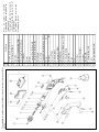
The drawing and the list are parts
structural drawing and parts list of
model DN7DV.
For model DN7DT refer to the
drawing and the list.
The exploded assembly drawing should be used only for authorized service center.
DN7DV
Page is loading ...

Italiano Nederlands Español
Batteria ricaricabile Oplaadbare accu Batería recargable
Fermo Vergrendeling Cierre
Estarre Uitnemen Extraer
Inserire Insteken Insertar
Impugnatura Handgreep Asidero
Spingere Drukken Presionar
Inserire Inbrengen Insertar
Lampada spia Kontrolelampje Lámpara piloto
Foro di collegamento della Opening voor aansluiting van Orificio para conectar la batería
batteria ricaricabile oplaadbare accu recargable
Anello Ring Anillo
Collare Klembus Manguito
Stringere Aandraaien Apretar
Allentare Losdraaien Aflojar
Levetta Keuzeschakelaar Palanca selectora
R
e
L
segno
R
en
L
-markeringen Marcas
R
y
L
Manopola d‘intercambio Verstelknop Perilla de cambio
Bassa velocità Lage snelheid Baja velocidad
Alta velocità Hoge snelheid Alta velocidad
Grilletto dell‘interruttore Trekschakelaar Interruptor de gatillo
English Deutsch Français
Rechargeable battery Batterie Batterie rechargeable
Latch Verriegelung Taquet
Pull out Herausziehen Extraire
Insert Einsetzen Insérer
Handle Handgriff Poignée
Push Drücken Pousser
Insert Einsetzen Insérer
Pilot lamp Kontrollampe Lampe-témoin
Hole for connecting the
Anschlußloch für Batterie
Trou pour connecter la batterie
rechargeable battery rechargeable
Ring Ring Anneau
Sleeve Manschette Manchon
Tighten Anziehen Serrer
Loosen Lösen Desserrer
Selector lever Wählhebel Levier-sélecteur
R
and
L
marks
R
und
L
Zeichen Repères
R
et
L
Shift knob Wählknopf Bouton de décalage
Low speed Kleine Geschwindigkeit Petite vitesse
High speed Große Geschwindigkeit Grande vitesse
Trigger switch Schalter Déclencheur
q
w
e
r
t
y
u
i
o
!0
!1
!2
!3
!4
!5
!6
!7
!8
!9
q
w
e
r
t
y
u
i
o
!0
!1
!2
!3
!4
!5
!6
!7
!8
!9

3
English
GENERAL OPERATIONAL PRECAUTIONS
1. Keep work area clean. Cluttered areas and benches
invite accidents.
2. Avoid dangerous environment. Don’t expose power
tools and charger to rain. Don’t use power tools
and charger in damp or wet locations. And keep
work area well lit. Never use power tools and
charger near flammable or explosive materials. Do
not use tool and charger in presence of flammable
liquids or gases.
3. Keep children away. All visitors should be kept
safe distance from work area.
4. Store idle tools and charger. When not in use,
tools and charger should be stored in dry, high
or locked-up place-out of reach of children. Store
tools and charger in a place where the tempera-
ture is less than 40°C.
5. Don’t force tool. It will do the job better and safer
at the rate for which it was designed.
6. Use right tool. Don’t force small tool or attach-
ment to do the job of a heavy duty tool.
7. Wear proper apparel. Do not wear clothing or
jewelry. They can be caught in moving parts.
Rubber gloves and footwear are recommended
when working outdoor.
8. Use eye protection with most tools. Also use face
or dust mask if cutting operation is dusty.
9. Don’t abuse cord. Never carry charger by cord or
yank it to disconnect from receptacle. Keep cord
from heat, oil and sharp edges.
10. Secure work. Use clamps or a vise to hold work.
It’s safer than using your hand and it frees both
hands to operate tool.
11. Don’t overreach. Keep proper footing and balance
at all times.
12. Maintain tools with care. Keep tools sharp at all
times, and clean for best and safest performance.
Follow instructions for lubricating and changing
accessories.
13. When the charger is not in use, or when being
maintained and inspected, disconnect its power
cord from the AC outlet.
14. Remove chuck wrenches and wrenches. Form habit
of checking to see that wrenches are removed
from tool before turning it on.
15. Avoid accidental starting. Don’t carry tool with
finger on switch.
16. To avoid danger, always use only the specified
charger.
17. Use only original HITACHI replacement parts.
18. Do not use power tools for applications other than
those specified in the Handling Instructions.
19. To avoid personal injury, use only the accessories
or attachment recommended in these handling
instructions or in the HITACHI catalog.
20. Let only the authorized service facility do the
repairing. The Manufacturer will not be respon-
sible for any damages or injuries caused by repair
by the unauthorized persons or by mishandling
of the tool.
21. To ensure the designed operational integrity of
power tools and charger, do not remove installed
covers or screws.
22. Always use the charger at the voltage specified
on the nameplate.
23. Do not touch movable parts or accessories unless
the power source has been disconnected.
24. Always charge the battery before use.
25. Never use a battery other than that specified. Do
not connect a usual dry cell, a rechargeable battery
other than that specified or a car battery to the
power tool.
26. Do not use any transformer that has a booster.
27. Do not charge the battery from an engine electric
generator or DC power supply.
28. Always charge indoors. Because the charger and
battery heat slightly during charging, charge the
battery in a place not exposed to direct sunlight;
where the humidity is low and the ventilation
good.
29. Before starting to work in a high place, pay at-
tention to the activities below to make sure there
are no people below.
30. Use the exploded assembly drawing on this
handling instructions only for authorized servic-
ing.
PRECAUTIONS FOR CORDLESS DRIVER DRILL
1. Always charge the battery at a temperature of 10 –
40°C. A temperature of less than 10°C will result
in over charging which is dangerous. The battery
cannot be charged at a temperature higher than
40°C. The most suitable temperature for charging
is that of 20 – 25°C.
2. Do not use the charger continuously.
When one charging is completed, leave the charger
for about 15 minutes before the next charging of
battery.
3. Do not charge the battery for more than 1 hour.
The battery will be fully charged in about 1 hour
and charging should be stopped when 1 hour has
elapsed from commencement. Disconnect the
charger power cord from the AC outlet.
4. Do not allow foreign matter to enter the hole for
connecting the rechargeable battery.
5. Never disassemble the rechargeable battery and
charger.
6. Never short-circuit the rechargeable battery. Short-
circuiting the battery will cause a great electric
current and overheat. It results in burn or damage
to the battery.
7. Do not dispose of the battery in fire.
If the battery is burnt, it may explode.
8. When drilling in wall, floor or ceiling, check for
buried electric power cord, etc.
9. Bring the battery to the shop from which it was
purchased as soon as the post-charging battery
life becomes too short for practical use. Do not
dispose of the exhausted battery.
10. Using an exhausted battery will damage the
charger.
11. Do not insert object into the air ventilation slots
of the charger.
Inserting metal objects or inflammables into the
charger air ventilation slots will result in electrical
shock hazard or damaged charger.

4
English
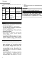
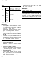
SPECIFICATIONS
POWER TOOL
Model DN7DT DN7DV
No-load speed (Low/High) 280/700/min. 0 – 280/0 – 700/min.
Drilling
Wood 15 mm
Metal Steel: 10 mm, Aluminum: 10 mm
Driving
Wood screw 5.1 mm (diameter) x 35 mm (length)
Tapping screw 4 mm (diameter) x 20 mm (length)
Rechargeable battery (EB7) Ni-Cd battery, 7.2 V
Weight 1.2 kg
Sound presser level Not exceed 70 dB (A)
Vibration level Not exceed 2.5 m/S
2
Capacity
CHARGER
Model UC7SB
Charging time Approx. 1 hour (at 20°C)
Charging voltage 7.2 V
Weight 1.0 kg
STANDARD ACCESSORIES
DN7DT (1HCK)
DN7DV (1HCK)
1 Plus driver bit (No. 2) ...................................................................... 1
2 Charger (UC7SB) ............................................................................. 1
3 Plastic case ....................................................................................... 1
Standard accessories are subject to change without notice.
OPTIONAL ACCESSORIES ......(sold separately)
1. Battery (EB7)
2. Plus Driver Bit
Bit No. Screw size
No. 1 2 – 2.5 mm
No. 2 3 – 5 mm
No. 3 6 – 8 mm
Bit No.
1
2
3

5
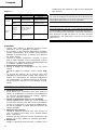
English
USES LOW SPEED HIGH SPEED
Drilling
Wood
In case the
diameter is over
13 mm
In case the
diameter is 13
mm or below.
Metal —
Use a drill bit for
steel
Driving
Tapping
screw, &
machine
screw
Driving machine
screws in general
—
Wood
screw
In case screw size
is over 3.5 mm
—
3. Minus Driver Bit
a Screw size
0.8 mm 4 mm
1 mm 5 – 6 mm
a
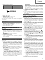
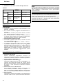
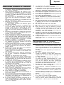
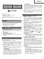
PRIOR TO OPERATION
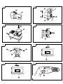
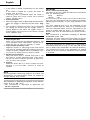
1. Mounting and dismounting of the bit.
(1) Mounting the bit
After inserting a driver bit, etc. into the keyless drill
chuck, firmly grasp the ring and tighten the sleeve
by turning it toward the right (in the clockwise
direction as viewed from the front). (See Fig. 4)
䡬 If the sleeve becomes loose during operation, tighten
it further. The tightening force becomes stronger
when the sleeve is tightened.
(2) Dismounting the bit
Firmly grasp the ring and loosen the sleeve by
turning it toward the left (in the counter-clockwise
direction as viewed from the front). (See Fig. 4)
2. Confirm that the battery is mounted correctly.
3. Check the rotational direction.
When the selector lever is set to
R
, the drill rotates
clockwise when viewed from the drill rear. When
set to
L
, the drill rotates counterclockwise. (See
Fig. 5) (The
L
and
R
marks are provided on the
body)
CAUTION
䡬 When the trigger switch is depressed, the se-
lector lever cannot be moved. Always release
the trigger switch to move the selector lever.
4. Change rotation speed
Operate the shift knob to change the rotational
speed. Move the shift knob in the direction of the
arrow. (See Figs. 6 and 7)
When the shift knob is set to “LOW”, the drill
rotates at a low speed. When set to “HIGH”, the
drill rotates at a high speed. If the shift knob cannot
be moved smoothly, clasp the drill chuck by hand
and rotate the spindle slightly.
CAUTIONS
䡬 When changing the rotational speed with the
shift knob, confirm that the switch is off. Chang-
ing the speed while the motor is rotating will
damage the gears.
䡬 To mesh the gears, certainly move the shift knob
so that the “LOW” or “HIGH” mark can fully be
seen. (See Figs. 6 and 7)
5. Change the speed depending upon uses.
Table 1
HOW TO USE
CAUTIONS
䡬 While operating the driver drill, take care not to lock
the motor.
4. Drill bit for steel
Diameter, 2 mm, 5 mm, 6 mm.
5. Drill bit for wood
Diameter, 10 mm, 13 mm.
Optional accessories are subject to change without
notice.
APPLICATIONS
䡬 Driving and removing of machine screws, wood
screws, tapping screws, etc.
䡬 Drilling of various metals.
䡬 Drilling of various woods.
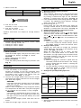
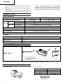
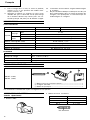
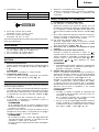
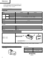
BATTERY REMOVAL/INSTALLATION
1. Battery removal
Hold the handle tightly and push the battery latch
to remove the battery (see Figs. 1 and 2).
CAUTION
Never short-circuit the battery.
2. Battery installation
Insert the battery while observing its polarities (see
Fig. 2).
CHARGING
Before using the driver drill, charge the battery as follows.
1. Insert the battery in the charger.
Position the battery so that the nameplate faces
toward the nameplate of the charger and press in
the battery until it comes into contact with the
bottom plate. (See Figs. 1 and 3.)
2. Connect the charger power cord to the AC outlet.
Connecting the power cord will turn on the charger
(the pilot lamp lights).
CAUTION
If the pilot lamp does not light, pull out the power
cord from the AC outlet and check the battery
mounting condition.
About 1 hour is required to fully charge the battery
at a temperature of about 20°C. The pilot lamp goes
off to indicate that the battery is fully charged.
CAUTION
If the battery is heated due to direct sunlight, etc.,
just after operation, the charger pilot lamp may
not light. At that time cool the battery first, then
start charging.
3. Disconnect the charger power cord from the AC
outlet.
4. Hold the charger tight and pull out the battery.

6
English
䡬 If the motor is locked, immediately turn the power
off.
If the motor is locked for a while, the motor or
battery may be burnt.
䡬 A buzzing noise is produced when the motor is
about to rotate. This is only a noise, not a machine
failure. (DN7DV only.)
1. Switch operation
䡬 When the trigger switch is depressed, the tool rotates.
When the trigger is released, the tool stops. (Fig.
8)
䡬 The rotational speed of the drill can be controlled
by varying the amount that the trigger switch is
pulled. Speed is low when the trigger switch is
pulled slightly and increases as the switch is pulled
more. (DN7DV only).
MAINTENANCE AND INSPECTION
1. Inspecting the tool
Since use of a dull tool will degrade efficiency and
cause possible motor malfunction, sharpen or re-
place the tool as soon as abrasion is noted.
2. Inspecting the mounting screws
Regularly inspect all mounting screws and ensure
that they are properly tightened. Should any of the
screws be loose, retighten them immediately. Fail-
ure to do so could result in serious hazard.
3. Cleaning on the outside
When the driver drill is stained, wipe with a soft
dry cloth or a cloth moistened with soapy water.
Do not use chloric solvents, gasoline or paint thin-
ner, for they melt plastics.
4. Storage
Store the driver drill in a place in which the tem-
perature is less than 40°C and out of reach of
children.
IMPORTANT
Correct connection of the plug
The wires of the mains lead are coloured in accordance
with the following code:
Blue: –Neutral
Brown: –Live
As the colours of the wires in the mains lead of this
tool may not correspond with the coloured markings
identifying the terminals in your plug proceed as fol-
lows:
The wire coloured blue must be connected to the
terminal marked with the letter N or coloured black.
The wire coloured brown must be connected to the
terminal marked with the letter L or coloured red.
Neither core must be connected to the earth terminal.
NOTE
This requirement is provided according to BRITISH
STANDARD 2769: 1984.
Therefore, the letter code and colour code may not be
applicable to other markets except United Kingdom.
The noise emitted by this power tool is measured in
accordance with IEC 59 (CO) 11, IEC 704, DIN 45 635
Part 21, NFS 31-031 (84/537/EEC for concrete breakers).
The sound pressure level at the workplace can exceed
85 dB (A); in this case noise protection for the operator
is required.
NOTE
Due to HITACHI’s continuing program of reserch and
development, the specifications herein are subject to
change without prior notice.
This appliance is produced to conform to the require-
ments of B. S. 800: 1977*.
* This requirement is applicable to appliances for
UNITED KINGDOM.
Page is loading ...
Page is loading ...
Page is loading ...
Page is loading ...
Page is loading ...
Page is loading ...
Page is loading ...
Page is loading ...
Page is loading ...
Page is loading ...
Page is loading ...
Page is loading ...
Page is loading ...
Page is loading ...
Page is loading ...
Page is loading ...
Page is loading ...
Page is loading ...
Page is loading ...
Page is loading ...
Page is loading ...

001
Code No. C99066171
Italiano
DICHIARAZIONE DI CONFORMITÀ CE
Si dichiara sotto nostra responsabilità che questo
prodotto è conforme agli standard o ai documenti
standardizzati EN50144, HD400, EN55014, EN60555
e/o EN50082-1 conforme alle direttive 73/23/CEE,
89/392/CEE e/o 89/336/CEE del concilio.
* Questa dichiarazione è applicabile ai prodotti cui sono
applicati i marchi CE.
Nederlands
EC VERKLARING VAN CONFORMITEIT
Wij verklaren onder eigen verantwoordelijkheid dat dit
produkt conform de richtlijnen of gestandardiseerde
documenten EN50144, HD400, EN55014, EN60555 en/
of EN50082-1 voldoet aan de eisen van EEG Bepalingen
73/23/EEG, 89/392/EEG en/of 89/336/EEG.
* Deze verklaring is van toepassing op produkten
voorzien van de CE-markeringen.
Español
DECLARACIÓN DE CONFORMIDAD DE LA CE
Declaramos bajo nuestra única responsabilidad que
este producto está de acuerdo con las normas o con
los documentos de normalización EN50144, HD400,
EN55014, EN60555 y/o EN50082-1, según indican las
Directrices del Consejo 73/23/CEE, 89/392/CEE y/o 89/
336/CEE.
* Esta declaración se aplica a los productos con marcas
de la CE.
English
EC DECLARATION OF CONFORMITY
We declare under our sole responsibility that this
product is in conformity with standards or standard-
ized documents EN50144, HD400, EN55014, EN60555
and/or EN50082-1 in accordance with Council Directives
73/23/EEC, 89/392/EEC and/or 89/336/EEC.
* This declaration is applicable to the product affixed
CE marking.
Deutsch
ERKLÄRUNG ZUR KONFORMITÄT MIT CE-REGELN
Wir erklären mit alleiniger Verantwortung, daß dieses
Produkt den Standards oder standardisierten
Dokumenten EN50144, HD400, EN55014, EN60555 und/
oder EN50082-1 in Übereinstimmung mit den Direktiven
des Europarats 73/23/EWG, 89/392/EWG und/order 89/
336/EWG entspricht.
* Diese Erklärung gilt für Produkte, die die CE-
Markierung tragen.
Français
DECLARATION DE CONFORMITE CE
Nous déclarons sous notre seule et entière respon-
sabilité que ce produit est conforme aux normes ou
documents normalisés EN50144, HD400, EN55014,
EN60555 et/ou EN50082-1 en accord avec les Directives
73/23/CEE, 89/392/CEE et/ou 89/336/CEE du Conseil.
*Cette déclaration s’applique aux produits désignés CE.
Hitachi Power Tools Europe GmbH
Siemensring 34, 47877 Willich, F. R. Germany
Hitachi Koki Co., Ltd.
Shinagawa Intercity Tower A, 15-1, Konan 2-chome,
Minato-ku, Tokyo, Japan
Y. Hirano
95
-
 1
1
-
 2
2
-
 3
3
-
 4
4
-
 5
5
-
 6
6
-
 7
7
-
 8
8
-
 9
9
-
 10
10
-
 11
11
-
 12
12
-
 13
13
-
 14
14
-
 15
15
-
 16
16
-
 17
17
-
 18
18
-
 19
19
-
 20
20
-
 21
21
-
 22
22
-
 23
23
-
 24
24
-
 25
25
-
 26
26
-
 27
27
-
 28
28
-
 29
29
-
 30
30


Hikoki DN 7DT Owner's manual
- Category
- Power tools
- Type
- Owner's manual
Ask a question and I''ll find the answer in the document
Finding information in a document is now easier with AI
in other languages
- italiano: Hikoki DN 7DT Manuale del proprietario
- français: Hikoki DN 7DT Le manuel du propriétaire
- español: Hikoki DN 7DT El manual del propietario
- Deutsch: Hikoki DN 7DT Bedienungsanleitung
- Nederlands: Hikoki DN 7DT de handleiding
Related papers
Other documents
-
Hitachi UC 14SD Handling Instructions Manual
-
Ferm LBM1010 User manual
-
-
-
Hitachi DS 12DVF3 Handling Instructions Manual
-
-
Infocus DS 12DM User manual
-
-
Hitachi DS 18 DVF3 Owner's manual
-