Page is loading ...

USER’S GUIDE
Dynamic Measurement DC Source
HP Model 66332A
System DC Power Supply
HP Model 6631B, 6632B, 6633B, 6634B
For instruments with Serial Numbers:
HP 66332A: US36320401 and up
HP 6631B: US37470101 and up
HP 6632B: US36350826 and up
HP 6633B: US36390236 and up
HP 6634B: US36380206 and up
HP Part No. 5962-8196
Microfiche Part No. 5962-8197
Printed in USA: July 1999

2
Warranty Information
CERTIFICATION
Hewlett-Packard Company certifies that this product met its published specifications at time of shipment
from the factory. Hewlett-Packard further certifies that its calibration measurements are traceable to the
United States National Bureau of Standards, to the extent allowed by the Bureau's calibration facility, and to
the calibration facilities of other International Standards Organization members.
WARRANTY
This Hewlett-Packard hardware product is warranted against defects in material and workmanship for a
period of three years from date of delivery. HP software and firmware products, which are designated by
HP for use with a hardware product and when properly installed on that hardware product, are warranted
not to fail to execute their programming instructions due to defects in material and workmanship for a
period of 90 days from date of delivery. During the warranty period Hewlett-Packard Company will, at its
option, either repair or replace products which prove to be defective. HP does not warrant that the
operation for the software firmware, or hardware shall be uninterrupted or error free.
For warranty service, with the exception of warranty options, this product must be returned to a service
facility designated by HP. Customer shall prepay shipping charges by (and shall pay all duty and taxes) for
products returned to HP for warranty service. Except for products returned to Customer from another
country, HP shall pay for return of products to Customer.
Warranty services outside the country of initial purchase are included in HP's product price, only if
Customer pays HP international prices (defined as destination local currency price, or U.S. or Geneva
Export price).
If HP is unable, within a reasonable time to repair or replace any product to condition as warranted, the
Customer shall be entitled to a refund of the purchase price upon return of the product to HP.
LIMITATION OF WARRANTY
The foregoing warranty shall not apply to defects resulting from improper or inadequate maintenance by
the Customer, Customer-supplied software or interfacing, unauthorized modification or misuse, operation
outside of the environmental specifications for the product, or improper site preparation and maintenance.
NO OTHER WARRANTY IS EXPRESSED OR IMPLIED. HP SPECIFICALLY DISCLAIMS THE IMPLIED
WARRANTIES OF MERCHANTABILITY AND FITNESS FOR A PARTICULAR PURPOSE.
EXCLUSIVE REMEDIES
THE REMEDIES PROVIDED HEREIN ARE THE CUSTOMER'S SOLE AND EXCLUSIVE REMEDIES. HP
SHALL NOT BE LIABLE FOR ANY DIRECT, INDIRECT, SPECIAL, INCIDENTAL, OR CONSEQUENTIAL
DAMAGES, WHETHER BASED ON CONTRACT, TORT, OR ANY OTHER LEGAL THEORY.
ASSISTANCE
The above statements apply only to the standard product warranty. Warranty options, extended support
contacts, product maintenance agreements and customer assistance agreements are also available.
Contact your nearest Hewlett-Packard Sales and Service office for further information on HP's full line of
Support Programs.

3
Safety Summary
The following general safety precautions must be observed during all phases of operation of this instrument.
Failure to comply with these precautions or with specific warnings elsewhere in this manual violates safety
standards of design, manufacture, and intended use of the instrument. Hewlett-Packard Company assumes no
liability for the customer's failure to comply with these requirements.
GENERAL
This product is a Safety Class 1 instrument (provided with a protective earth terminal). The protective features of
this product may be impaired if it is used in a manner not specified in the operation instructions.
Any LEDs used in this product are Class 1 LEDs as per IEC 825-1.
ENVIRONMENTAL CONDITIONS
This instrument is intended for indoor use in an installation category II, pollution degree 2 environment. It is
designed to operate at a maximum relative humidity of 95% and at altitudes of up to 2000 meters. Refer to the
specifications tables for the ac mains voltage requirements and ambient operating temperature range.
BEFORE APPLYING POWER
Verify that the product is set to match the available line voltage, the correct fuse is installed, and all safety
precautions are taken. Note the instrument's external markings described under "Safety Symbols".
GROUND THE INSTRUMENT
To minimize shock hazard, the instrument chassis and cover must be connected to an electrical ground. The
instrument must be connected to the ac power mains through a grounded power cable, with the ground wire
firmly connected to an electrical ground (safety ground) at the power outlet. Any interruption of the protective
(grounding) conductor or disconnection of the protective earth terminal will cause a potential shock hazard that
could result in personal injury.
ATTENTION: Un circuit de terre continu est essentiel en vue du fonctionnement sécuritaire de l'appareil.
Ne jamais mettre l'appareil en marche lorsque le conducteur de mise … la terre est d‚branch‚.
FUSES
Only fuses with the required rated current, voltage, and specified type (normal blow, time delay, etc.) should be
used. Do not use repaired fuses or short-circuited fuseholders. To do so could cause a shock or fire hazard.
DO NOT OPERATE IN AN EXPLOSIVE ATMOSPHERE
Do not operate the instrument in the presence of flammable gases or fumes.
DO NOT REMOVE THE INSTRUMENT COVER
Operating personnel must not remove instrument covers. Component replacement and internal adjustments must
be made only by qualified service personnel.
Instruments that appear damaged or defective should be made inoperative and secured against unintended
operation until they can be repaired by qualified service personnel.

4
SAFETY SYMBOLS
Direct current
Alternating current
Both direct and alternating current
Three-phase alternating current
Earth (ground) terminal
Protective earth (ground) terminal
Frame or chassis terminal
Terminal is at earth potential. Used for measurement and control circuits designed to be
operated with one terminal at earth potential.
Terminal for Neutral conductor on permanently installed equipment
Terminal for Line conductor on permanently installed equipment
On (supply)
Off (supply)
Standby (supply). Units with this symbol are not completely disconnected from ac mains when
this switch is off. To completely disconnect the unit from ac mains, either disconnect the power
cord or have a qualified electrician install an external switch.
In position of a bi-stable push control
Out position of a bi-stable push control
Caution, risk of electric shock
Caution, hot surface
Caution (refer to accompanying documents)
WARNING
The WARNING sign denotes a hazard. It calls attention to a procedure, practice, or the like,
which, if not correctly performed or adhered to, could result in personal injury. Do not proceed
beyond a WARNING sign until the indicated conditions are fully understood and met.
Caution
The CAUTION sign denotes a hazard. It calls attention to an operating procedure, or the like,
which, if not correctly performed or adhered to, could result in damage to or destruction of part
or all of the product. Do not proceed beyond a CAUTION sign until the indicated conditions are
fully understood and met.

5
Declaration Page
DECLARATION OF CONFORMITY
according to ISO/IEC Guide 22 and EN 45014
Manufacturer's Name: Hewlett-Packard Company
Manufacturer's Address: 150 Green Pond Road
Rockaway, New Jersey 07866
U.S.A.
declares that the Product
Product Name: a) Dynamic Measurement DC Source
b) System DC Power Supply
Model Number: a) HP 66332A
b) HP 6631B, 6632B, 6633B, 6634B
conforms to the following Product Specifications:
Safety: IEC 1010-1:1990+A1(1992) / EN 61010-1:1993
EMC: CISPR 11:1990 / EN 55011:1991 - Group 1 Class B
IEC 801-2:1991 / EN 50082-1:1992 - 4 kV CD, 8 kV AD
IEC 801-3:1984 / EN 50082-1:1992 - 3 V / m
IEC 801-4:1988 / EN 50082-1:1992 - 0.5 kV Signal Lines
1 kV Power Lines
Supplementary Information:
The product herewith complies with the requirements of the Low Voltage Directive
73/23/EEC and the EMC Directive 89/336/EEC and carries the CE-marking accordingly.
New Jersey November 1997 ______
Location Date Bruce Krueger / Quality Manager
European Contact: Your local Hewlett-Packard Sales and Service Office or Hewlett-Packard GmbH,
Department TRE, Herrenberger Strasse 130, D-71034 Boeblingen (FAX:+49-7031-14-3143)

6
Acoustic Noise Information
Herstellerbescheinigung
Diese Information steht im Zusammenhang mit den Anforderungen der
Maschinenläminformationsverordnung vom 18 Januar 1991.
* Schalldruckpegel Lp <70 dB(A)
* Am Arbeitsplatz
* Normaler Betrieb
* Nach EN 27779 (Typprüfung).
Manufacturer's Declaration
This statement is provided to comply with the requirements of the German Sound Emission Directive, from
18 January 1991.
* Sound Pressure Lp <70 dB(A)
* At Operator Position
* Normal Operation
* According to EN 27779 (Type Test).
Printing History
The edition and current revision of this manual are indicated below. Reprints of this manual
containing minor corrections and updates may have the same printing date. Revised editions are
identified by a new printing date. A revised edition incorporates all new or corrected material since
the previous printing date.
Changes to the manual occurring between revisions are covered by change sheets shipped with the
manual. In some cases, the manual change applies only to specific instruments. Instructions
provided on the change sheet will indicate if a particular change applies only to certain instruments.
This document contains proprietary information protected by copyright. All rights are reserved.
No part of this document may be photocopied, reproduced, or translated into another language
without the prior consent of Hewlett-Packard Company. The information contained in this
document is subject to change without notice.
Copyright 1997 Hewlett-Packard Company Edition 1 __________November, 1997

7
Table of Contents
Warranty Information 2
Safety Summary 3
Acoustic Noise Information 6
Printing History 6
Table of Contents 7
QUICK REFERENCE 9
HP 66332A Dynamic Measurement DC Source and
HP 6611C-6614C System DC Power Supply 9
The Front Panel - At a Glance 10
Front Panel Number Entry 11
Front Panel Annunciators 12
Immediate Action Keys 12
Front Panel Menus - At a Glance 13
SCPI Programming Commands - At a Glance 14
The Rear Panel - At a Glance 15
GENERAL INFORMATION 17
Document Orientation 17
Safety Considerations 18
Options and Accessories 18
Description 19
Capabilities 19
Front Panel Controls 19
Remote Programming 19
Output Characteristic 20
INSTALLATION 21
Inspection 21
Damage 21
Packaging Material 21
Items Supplied 21
Cleaning 21
Location 22
Bench Operation 22
Rack Mounting 22
Input Connections 23
Connect the Power Cord 23
Output Connections 23
Wire Considerations 23
Current Ratings 23
Voltage Drops 24
Multiple Load Connections 24
Remote Sense Connections 24
Sense Leads 25
Stability 26
OVP Considerations 26
Fast/Normal Operation 27
Inductive Loading 27
Capacitive Loading 27
INH/FLT Connections 27
Controller Connections 30
HP-IB Interface 30
RS-232 Interface 30

8
TURN-ON CHECKOUT 31
Introduction 31
Using the Keypad 31
Checkout Procedure 32
In Case of Trouble 34
Error Messages 34
Line Fuse 34
FRONT PANEL OPERATION 35
Introduction 35
Front Panel Description 35
System Keys 37
Function Keys 38
Immediate Action Keys 38
Scrolling Keys 38
Metering Keys 39
Output Control Keys 40
Entry Keys 41
Examples of Front Panel Programming 42
1 - Setting the Output Voltage and Current 42
2 - Querying and Clearing Output Protection 43
3 - Making Front Panel Measurements 43
4 - Programming the Digital Output Port 45
5 - Programming the Output Relay (option 760 only) 46
6 - Setting the HP-IB Address and RS-232 Parameters 46
7 - Saving and Recalling Operating States 47
SPECIFICATIONS 49
Specifications 49
Supplemental Characteristics 50
VERIFICATION AND CALIBRATION 53
Introduction 53
Equipment Required 53
Test Setup 53
Performing the Verification Tests 54
Turn-On Checkout 55
Voltage Programming and Measurement Accuracy 55
Current Programming and Measurement Accuracy 55
Performing the Calibration Procedure 59
Front Panel Calibration Menu 59
Front Panel Calibration 60
Calibration Error Messages 62
Changing the Calibration Password 63
Calibration Over the HP-IB 63
ERROR MESSAGES 65
LINE VOLTAGE CONVERSION 69
Open the Unit 69
Configure the Power Transformer 69
Install the Correct Line Fuse 70
Close the Unit 70
INDEX 71

9
1
Quick Reference
HP 66332A Dynamic Measurement DC Source and
HP 6631B/6632B/6633B/6634B System DC Power
Supplies
The HP 66332A is a 100 Watt, high performance dc power supply that provides dynamic
measurement and analysis of voltage and current waveforms. It is designed to simplify the testing
of digital cellular and mobile phones. For example, data acquired using its dynamic measurement
capability can be used in determining the battery operating time of digital wireless communications
products.
The HP 6631B/6632B/6633B/6634B are 100 Watt, high performance dc power supplies with
output current measurement capability in the microampere range. They are well suited for testing
portable battery-powered products.
Additionally, the combination of bench-top and system features in these dc sources provide
versatile solutions for your design and test requirements.
Convenient bench-top features
♦ Up to 100 Watts output power
♦ Easy to use knob for voltage and current settings
♦ Highly visible vacuum-fluorescent front panel display
♦ Excellent load and line regulation; low ripple and noise
♦ Measurement capability down to microampere levels
♦ Current sinking up to the maximum rated output current
♦ Instrument state storage
♦ Portable case
Flexible system features
♦ HP-IB (IEEE-488) and RS-232 interfaces are standard
♦ SCPI (Standard Commands for Programmable Instruments) compatibility
♦ Triggered acquisition of digitized output current and voltage waveforms (HP 66332A only)
♦ I/O setup easily done from the front panel

1 – Quick Reference
10
The Front Panel - At a Glance
j14-character
display shows output
measurements and
programmed values.
kAnnunciators
indicate operating
modes and status
conditions.
lRotary control
sets voltage, current,
and menu parameters.
Use and
to set the resolution;
then adjust the value
with the knob.
mOptional front panel
output connectors.
5
6
7
8
1
2 3
4
nTurns the dc source
on and off.
o System keys:
♦ return to Local
mode
♦ set the HP-IB
address
♦ set the RS-232
interface
♦ display SCPI
error codes
♦ save and recall
instrument states.
p Function keys:
♦ enable/disable
output
♦ select metering
functions
♦ program voltage
and current
♦ set and clear
protection
functions
♦ and
scroll through the
front panel menu
commands.
qEntry keys:
♦ enter values
♦ increment or
decrement values
♦ and
select front panel
menu parameters.
♦ and
select a digit in
the numeric entry
field.
âá
â
á
ãä
•‚

1 – Quick Reference
11
Front Panel Number Entry
Enter numbers from the front panel using one of the following methods:
Use the arrow keys and knob to change voltage or current settings
NOTE The output must be ON to see the displayed values change in Meter mode.
Use the Function keys and knob to change the displayed settings
Use the Arrow keys to edit individual digits in the displayed setting
Increments the flashing digit
Decrements the flashing digit
Moves the flashing digit to the right
Moves the flashing digit to the left
Enters the value when editing is complete
Use the Function keys and Entry keys to enter a new value
NOTE If you make a mistake, use the Backspace key to delete the number, or press the
Meter key to return to meter mode.

1 – Quick Reference
12
Front Panel Annunciators
CV
The output is operating in constant voltage mode.
CC
The output is operating in constant current mode.
Unr
The output is unregulated.
Dis
The output is OFF. Press the Output On/Off key to turn the
output on.
OCP
The over-current protection state is ON. Press the OCP key to
turn over-current protection off.
Prot
Indicates that the output has been disabled by one of the
protection features. Press the Prot Clear key to clear the
protection condition.
Cal
Calibration mode is ON. Scroll to the Cal Off command and
press the Enter key to exit the calibration mode.
Shift
The Shift key has been pressed.
Rmt
The selected Remote programming interface (either HP-IB or
RS-232) is active. Press the Local key to return the unit to
front panel control.
Addr
The interface is addressed to talk or listen.
Err
There is an error in the SCPI error queue. Press the Error key
to view the error code.
SRQ
The interface is requesting service.
Immediate Action Keys
A toggle switch that turns the output of the dc source on
or off.
Activates front panel control when the unit is in remote
mode (unless a Lockout command is in effect).
Resets the protection circuit and allows the unit to return
to its last programmed state.
A toggle switch that enables or disables overcurrent
protection.
Output
On/Off
Local
Prot ClrShift
OCP
Shift

1 – Quick Reference
13
Front Panel Menus - At a Glance
ADDRESS 7 Sets the HP-IB Address
INTF HPIB Selects an interface (HPIB or RS232)
BAUDRATE 300 Selects baud rate (300, 600, 1200, 2400, 4800, 9600)
PARITY NONE Selects message parity (NONE, EVEN, ODD, MARK, SPACE)
FLOW NONE Selects flow control (XON-XOFF, RTS-CTS, DTR-DSR, NONE)
LANG SCPI Selects language (SCPI or COMP)
*RCL 0 Recalls instrument state
*SAV 0 Saves present instrument state
ERROR 0 Displays errors in SCPI error queue
12.000V 0.204A Measures output voltage and current
12.500V MAX Measures peak output voltage
1
1.000V MIN Measures minimum output voltage
1
12.330V HIGH Measures the high level of a voltage pulse waveform
1
0.080V LOW Measures the low level of a voltage pulse waveform
1
12.000V RMS Measures rms voltage
1
0.350A MAX Measures peak output current
1
0.050A MIN Measures minimum output current
1
0.400A HIGH Measures the high level of a current pulse waveform
1
0.012A LOW Measures the low level of a current pulse waveform
1
0.210A RMS Measures rms current
1
VOLT 20.000 Sets the output voltage
CURR 2.000 Sets the output current
OC -- -- -- -- Protection status (example shows overcurrent tripped)
*RST Places the dc source in the factory-default state
PON:STATE RST Select the power-on state command (RST or RCL0)
PROT:DLY 0.08 Sets the output protection delay in seconds
RI LATCHING Sets the remote inhibit mode (LATCHING, LIVE, or OFF)
DFI OFF Sets the discrete fault indicator state (ON or OFF)
DFI:SOUR OFF Selects the DFI source (QUES, OPER, ESB, RQS, or OFF)
PORT RIDFI Sets the output port functions (RIDFI or DIGIO)
DIGIO 7 Sets and reads the I/O port value (0 through 7)
RELAY ON Sets the output relay state (ON or OFF)
2
RELAY NORM Sets the output relay polarity (NORM or REV)
2
VOLT:PROT 22 Sets overvoltage protection level
CURR:RANG HIGH Sets current range (HIGH, LOW, or AUTO)
CURR:DET ACDC Sets current measurement detector (ACDC or DC)
1
CAL ON Accesses calibration menu (See User’s Guide).
Use and to select menu parameters. Use to exit any menu and return to metering mode.
1
Not available on HP 6631B - 6634B or in Compatibility mode.
2
Not available on HP 6631B.
Address
‚
‚
‚
‚
‚
Recall
SaveShift
ErrorShift
Meter
‚
‚
‚
‚
‚
‚
‚
‚
‚
‚
Voltage
Current
Protect
Output
‚
‚
‚
‚
‚
‚
‚
‚
‚
OV
Shift
Shift Input
‚
CalShift
Meter
ãä

1 – Quick Reference
14
SCPI Programming Commands - At a Glance
NOTE Most [optional] commands have been omitted for clarity. Refer to the
Programming Guide for a complete description of all programming commands.
ABORt SENSe
CALibrate
:CURRent :RANGe <n>
:CURRent [:POSitive] :DETector ACDC | DC
1
:NEGative :FUNCtion “VOLT” | “CURR”
1
:MEASure :LOWRange :SWEep :OFFSet :POINts <n>
1
:AC
1
:POINts <n>
:DATA <n> :TINTerval <n>
:LEVel P1 | P2 | P3 | P4 [SOURce:] CURRent <n>
:PASSword <n> :TRIGgered <n>
:SAVE :PROTection :STATe <bool>
:STATe <bool> [, <n>] DIGital :DATA <n>
:VOLTage :PROTection :FUNCtion RIDF | DIG
DISPlay
VOLTage <n>
<bool> :TRIGgered <n>
:MODE NORMal | TEXT :PROTection <n>
:TEXT <display_string> :ALC :BANDwidth? | :BWIDth?
INITiate STATus
:SEQuence[1|2
1
] :PRESet
:NAME TRANsient | ACQuire
1
:OPERation [:EVENt]?
:CONTinuous :SEQuence[1], <bool> :CONDition?
:NAME TRANsient, <bool> :ENABle <n>
MEASure | FETCh
:NTRansition <n>
:ARRay :CURRent?
1
:PTRansition <n>
:VOLTage?
1
:QUEStionable [:EVENt]?
[:CURRent][:DC]?
2
:CONDition?
:ACDC?
1
:ENABle <n>
:HIGH?
1
:NTRansition <n>
:LOW?
1
:PTRansition <n>
:MAX?
1
SYSTem
:MIN?
1
:ERRor?
:VOLTage [:DC]?
2
:LANGuage SCPI | COMPatibility
:ACDC?
1
:VERSion?
:HIGH?
1
:LOCal
:LOW?
1
:REMote
:MAX?
1
:RWLock
:MIN?
1
TRIGger
OUTPut
:SEQuence 2 | :ACQuire [:IMMediate]
1
<bool> [,NORelay] :COUNt :CURRent <n>
1
:DFI <bool> :VOLTage <n>
1
:SOURce QUES | OPER | ESB | RQS | OFF :HYSTeresis:CURRent <n>
1
:PON :STATe RST | RCL0 :VOLTage <n>
1
:PROTection :CLEar :LEVel :CURRent <n>
1
:DELay <n> :VOLTage <n>
1
:RELay [:STATe] <bool>
3
:SLOPe :CURRent POS | NEG | EITH
1
:POLarity NORM | REV
3
:VOLTage POS | NEG | EITH
1
:RI :MODE LATCHing | LIVE | OFF :SOURce BUS | INTernal
1
[:SEQuence1 | :TRANsient][:IMMediate]
1
Not available on HP 6631B - 6634B :SOURce BUS
2
Fetch commands not available on HP 6631B – 6634B :SEQuence1 :DEFine TRANsient
3
Not available on HP 6631B :SEQuence2 :DEFine ACQuire
1

1 – Quick Reference
15
The Rear Panel - At a Glance
jHP-IB (IEEE-488)
interface connector
kRS-232 interface
connector
lINH/FLT (remote
INHibit / internal
FauLT) connector.
Connector plug is
removable.
mOutput and Remote
sense terminal block.
3
2
1
5
6
7
4
nFast/Normal switch oFuse holder pPower cord
connector (IEC 320)
Use the front panel Address menu to
♦ Select the HP-IB or RS-232 interface (see chapter 4 in User’s Guide)
♦ Select the HP-IB bus address (see chapter 4 in User’s Guide)
♦ Configure the RS-232 interface (see chapter 4 in User’s Guide)


17
2
General Information
Document Orientation
This manual describes the operation of the HP Model 66332A Dynamic Measurement DC Source
and the HP Model 6631B/6632B/6633B/6634B System DC Power Supply. Unless otherwise
noted, both units will be referred to by the description "dc source" throughout this manual. The
following documents are shipped with your dc source:
♦ a User's Guide (this document), contains installation, checkout, and front panel information
♦ a Programming Guide, contains detailed HP-IB programming information
♦ an HP VXIplug&play instrument driver, for Windows 95 and Windows NT 4.0
The following Getting Started Map will help you find the information you need to complete the
specific task that you want to accomplish. Refer to the table of contents or index of each guide for
a complete list of the information contained within.
Getting Started Map
Task Where to find information
Installing the unit
Line voltage connections
Computer connections
Load connections
User’s Guide
Checking out the unit
Verifying proper operation
Using the front panel
Calibrating the unit
User’s Guide
Using the front panel
Front panel keys
Front panel examples
User’s Guide
Using the programming interface
HP-IB interface
RS-232 interface
User’s Guide
Programming Guide
Programming the unit using SCPI (and Compatibility)
commands
SCPI commands
SCPI programming examples
Compatibility language
Programming Guide
Programming the unit using the HP VXIplug&play
instrument driver
Installing the instrument driver
Instrument driver functions
C/C++ example programs
Visual BASIC example programs
LabVIEW example programs
HP VEE example programs
HP VXIplug&play installation sheet
and on-line help
NOTE:
The driver must be installed on your computer to
access the on-line information.
Drivers for HP-UX are available on the web at
www.hp.com/go/power

2 – General Information
18
Safety Considerations
This dc source is a Safety Class 1 instrument, which means it has a protective earth terminal. That
terminal must be connected to earth ground through a power source equipped with a ground
receptacle. Refer to the Safety Summary page at the beginning of this guide for general safety
information. Before installation or operation, check the dc source and review this guide for safety
warnings and instructions. Safety warnings for specific procedures are located at appropriate
places in the guide.
Options and Accessories
Table 2-1. Options
Option Description
100
87−106 Vac, 47−63 Hz
220
191−233 Vac, 47−63 Hz
230
207−253 Vac, 47−63 Hz
020 Front panel output binding posts
760 Isolation and polarity reversal relays (not available on HP 6631B)
1CM Rack mount kit (HP p/n 5062-3974)
1CP Rack mount kit with handles (HP p/n 5062-3975)
Accessory Rack slide kit )HP p/n 1494-0060)
910 Service manual with extra operating manuals
1
Support rails are required when rack mounting units. Use E3663A support rails for HP rack cabinets, and
E3664A for non-HP rack cabinets.
Table 2-2. Accessories
Item HP Part Number
HP-IB cables
1.0 meter (3.3 ft) 10833A
2.0 meters (6.6 ft) 10833B
4.0 meters (13.2 ft) 10833C
0.5 meters (1.6 ft) 10833D
RS-232 cable 34398A
(9-pin F to 9-pin F, 2.5 meter, null modem/printer cable
with one 9-pin M to 25-pin F adapter
RS-232 adapter kit (contains 4 adapters) 34399A
9-pin M to 25-pin M for pc or printer
9-pin M to 25-pin M for pc or printer
9-pin M to 25-pin M for modem
9-pin M to 9-pin M for modem

2 – General Information
19
Description
Both the HP 66332A Dynamic Measurement DC Source and the HP 6631B/6632B/6633B/6634B
System DC Power Supply combine two instruments in one unit. It includes a dc source, which
produces dc output with programmable voltage and current amplitude, and a highly accurate
voltage and current meter, with the capability to measure very low-level currents. Additionally,
the HP 66332A Dynamic Measurement DC Source has the ability to measure and characterize
output voltage and current of pulse or ac waveforms.
Capabilities
♦ Output Voltage and Current control with 12-bit programming resolution
♦ Extensive measurement capability:
dc voltage and current.
rms and peak voltage and current (HP 66332A only).
16-bit measurement resolution (low range accurate down to 2 microamperes).
Triggered acquisition of digitized current and voltage waveforms (HP 66332A
only).
♦ Front panel control with 14-character vacuum fluorescent display, keypad, and rotary
control for voltage and current settings.
♦ Built-in HP-IB and RS-232 interface programming with SCPI command language.
♦ Non-volatile state storage and recall.
♦ Over-voltage, over-current, over-temperature, and RI/DFI protection features.
♦ Extensive selftest, status reporting, and software calibration.
Front Panel Controls
The front panel has both rotary (RPG) and keypad controls for setting the output voltage and
current. The panel display provides digital readouts of a number of output measurements.
Annunciators display the operating status of the dc source. System keys let you perform system
functions such as setting the HP-IB address and recalling operating states. Front panel Function
keys access the dc source function menus. Front panel Entry keys let you select and enter
parameter values. Refer to chapter 5 for a complete description of the front panel controls.
Remote Programming
NOTE: When shipped, HP 6631B/6632B/6633B/6634B units are set to the
Compatibility programming language; HP 66332A units are set to the SCPI
programming language.
To change the programming language from Compatibility to SCPI, press the
front panel
Address key, use ô to scroll to the LANG command, press
to
select SCPI, then press
Enter. Refer to the Programming Guide supplied with
your dc source for further information about remote programming.
The dc source may be remotely programmed via the HP-IB bus and/or from an RS-232 serial
port. HP-IB programming is with SCPI commands (Standard Commands for Programmable
Instruments), which make the dc source programs compatible with those of other HP-IB
instruments. Compatibility commands are also included to make the dc source compatible with

2 – General Information
20
the HP 6632A, 6633A, and 6634A Series dc power supplies (refer to appendix D in the the
Programming Guide). Dc source status registers allow remote monitoring of a wide variety of dc
source operating conditions.
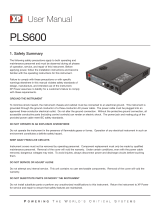
Output Characteristic
The dc source’s output characteristic is shown in the following figure. The output of the dc
source may be adjusted to any value within the boundaries shown.
Output
Voltage
Output
Current
Imax
Vmax
ISET-ISET
VSET
CC operating line
CV operating line
0
1
2
+
-
-Imax
Figure 2-1. Dc Source Output Characteristic
The dc source can operate in either constant voltage (CV) or constant current (CC) over the rated
output voltage and current. Although the dc source can operate in either mode, it is designed as a
constant voltage source. This means that the unit turns on in constant voltage mode with the
output voltage rising to its Vset value. There is no command for constant current operation. The
only way to turn the unit on in constant current mode is by placing a short across the output and
then enabling or turning the output on.
Note that the dc source cannot be programmed to operate in a specific mode. After initial turn-
on, the operating mode of the unit will be determined by the voltage setting, the current setting,
and the load resistance. In figure 2-1, operating point 1 is defined by the load line traversing the
positive operating quadrant in the constant voltage region. Operating point 2 is defined by the
load line traversing the positive operating quadrant in the constant current region.
Figure 2-1 also shows a single range − two quadrant capability. This means that the dc source is
capable of sourcing as well as sinking current over the output voltage range from zero volts to the
rated maximum. The negative quadrant is identical to the positive quadrant. However, the
negative current cannot be set independently; it tracks the value programmed for the positive
current. Thus, if the positive current is set to 1 A, the negative current is also set to 1 A.
NOTE: If you attempt to operate the dc source beyond its output ratings, the output of
the unit will become unregulated. This is indicated by the UNR annunciator on
the front panel. The output may also become unregulated if the ac input voltage
drops below the minimum rating specified in Appendix A.
Appendix A documents the dc source’s specifications and supplemental characteristics.
/