Page is loading ...

SwayControl Install Guide
TEAM
BMPRO
.COM
2. location
1. considerations
3. mounting
5. ground connections
4. wiring
6. 12V connections
Using four 10G hex head self-drilling screws, mount
the SwayControl to the caravan/trailer using the
mounting flanges on the sides of the unit.
Starlock washers are recommended.
Tightly secure the mounting screws to hold the
SwayControl firmly in position and to avoid becoming
loose from vibration.
BMPRO SwayControl is a proactive electronic stability control that can automatically stabilise a caravan/trailer in the event of
it’s sway. It automatically corrects caravan/trailer sway which can be caused by changing road conditions, driver error, lateral
winds or a passing truck keeping drivers safe on the road.
Electronic sway control is mounted on the underside of the caravan/trailer chassis, wires directly to the trailer braking
system and continuously monitors trailer yaw to detect sway. In the event that sway is detected the SwayControl automatically
activates the caravan/trailer brakes to bring both it and the vehicle under control.
The SwayControl must be installed by suitably qualified
service personnel.
For proper operation, ensure electric brakes are adjusted
and maintained according to the manufacturer’s
recommendations.
The caravan/trailer must be equipped with a 12V battery
system of greater or equal to 50Ahr.
A full size caravan/trailer battery must be used.
The SwayControl must be installed on the rear of the first trailer frame
crossmember, between 0.3 and 3m behind the trailer hitching point. It must:
• be in the centre of the crossmember.
• be in the correct orientation. Use the label on the SwayControl as a guide.
• be fastened hard against the floor of a steel trailer.
• have no overhang below the crossmember.
• not be mounted where it is affected by vibration.
The wire harness has five wires requiring connection and one cable for
the status LED light.
Solder joints are recommended when connecting to the caravan/trailer’s
wiring harness.
If solder joints are not possible, use the appropriate size and type of
“crimp-type” weather sealed heat-shrink connectors, using the
manufacturer’s recommended crimping tools and using their
instructions.
The caravan/trailer battery ground, the SwayControl ground
and the electric brake ground wires must be securely
connected a minimum 1.8 mm2 wire, all fully grounded to a
common point on the caravan/trailer.
The tow vehicle 12V charge line, the 12V caravan/trailer battery
terminal and the SwayControl 12V black wire must be securely
connected together with a minimum 1.8 mm2 wire.
The “hot” wire from the breakaway switch must be connected
to the +12V terminal of the caravan/trailer battery.
7. electric brake connections
The blue tow vehicle brake signal wire must be connected to
both the SwayControl blue brake signal wire and the “cold”
wire from the breakaway switch.
8. left & right brake connections
The SwayControl operates the left and right side
caravan/trailer brakes independently in order to control
caravan/trailer sway. It is very important the correct
SwayControl wires are connected to the correct side of the
brakes.
The SwayControl purple wire connects to all left side brakes.
The SwayControl pink wire connects to all right side brakes.
DOC PART 038655
REV 1.0

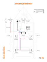
9. wiring diagram
TEAM
BMPRO
.COM
DOC PART 038655
REV 1.0
• Heat shrinks to seal conduits
are on all cables
• Heat shrinks are labelled to
ensure correct connections are
made
• Black positive wire connects to
red positive wire from battery
• White negative wire connects to
black negative wire from
battery
Red positive wire
Black negative wire
Blue wire - brake wire
White wire - earth wire
Pink wire - right brake
Purple wire - left brake
Black wire - status light

10. status light module installation
TEAM
BMPRO
.COM
MANUAL DATASHEET FAQs
11. status light LEDs
Once wiring is completed, route the Status Light cable to the
front of the trailer.
Using self-tapping screws, mount the Status Light module
onto a flat surface on the drawbar of the caravan/trailer.
Select a location that makes it easy to see the Status Light
when looking at the front of the trailer.
Condition or Fault
Status Light
Flash Sequence Solution
1 RED flash
2 RED flashes
3 RED flashes
4 RED flashes
Fast RED FLashing
System malfunction
Sensor malfunction - no sway control of trailer
Left side brake short
5 side brake short
Low voltage, between 3 and 6V
Service centre repair required
Service centre repair required
Correct the short in the left side brake
Correct the short in the right side brake
Check quality of power and ground connections
No Light
No Light
No Light
No Light
Continuous RED,
GREEN flash
1 GREEN flash
every 4 seconds
GREEN flash 5
times per second
Solid GREEN
pulsing Normal operation
SwayControl braking is active
Module reset to manufacturer default values. Keep
trailer still for 60 seconds (minimum) then drive
normally
Driving on rough terrain and SwayControl of trailer
is disabled
Unit in “sleep” mode
No power after “wake-up” from brake controller
Over voltage, greater than 20V detected
Low voltage, less than 3V detected
If module does not return to normal solid
GREEN pulsing light after 3 system restarts,
have the unit checked at a service centre
SwayControl of trailer is automatically disabled
when driving on rough terrain. Unit will return
to normal operation (GREEN light) when not on
rough terrain.
Activate manual override on the brake
controller to “wake-up” unit
Check quality of power, ground and brake
controller wire connections.
Check for any blown fuses on the tow vehicle
and trailer.
Check power source voltage, correct
voltage is 12-15V
Check power source voltage, correct voltage is
12-15V.
Check quality of power and ground connections.
DOC PART 038655
REV 1.0
/

