
INSTRUCTIONS
SAFETY GUARDRAIL
SYSTEMS
READ THESE INSTRUCTIONS CAREFULLY BEFORE USING THIS PRODUCT.
KEEP THIS MANUAL HANDY FOR FUTURE REFERENCE.
Picture may differ from actual product.
THIS EQUIPMENT MEETS ANSI,
NBC, CNESST, CSTC, RSST,
OBC, OSHA AND WORKSAFE BC
STANDARDS.
TABLE OF CONTENT
INSTRUCTIONS AND SAFETY ........ 2
PARTS ......................... 4
STACKABLE SYSTEM
• Configurations ............... 6
• Assembly .................. 9
STANDARD SYSTEM
• Configurations .............. 16
• Assembly ................. 20

2
INSTRUCTIONS
AND SAFETY
OPERATIONAL SAFETY
METAL CONDUCTS ELECTRICITY:
Do not use this equipment where contact may be made with power lines or other live electrical circuits.
FAILURE TO UNDERSTAND AND FOLLOW ALL SAFETY RULES AND ASSEMBLY INSTRUCTIONS
COULD RESULT IN SERIOUS INJURY OR DEATH.
READ BEFORE BEGINNING ASSEMBLY.
INSTRUCTIONS AND SAFETY
• Do not use this equipment if you are in poor health, taking medications, drugs, or have been consuming alcohol,
all of which may impair your ability to work safely on this product.
• Comply with local or national legislation that applies for the use of this type of equipment.
• Examine thoroughly to ensure that the guardrails are properly set up.
• Always check that the surface under the foot clamps and/or the guardrail bases are free of debris. Good adhesion is
necessary in order to avoid movements or slipping.
• Never use guardrails for purposes they were not intended for.
• Guardrails are not designed and should not be used as a fall protection anchor for workers.
• Inspect before use. Do not use this equipment if it is damaged or missing parts.
• Always inspect equipment before use to make sure it is working properly and that it is suitable for the needs.
• Always wear the mandatory protective equipment when installing guardrails.
• Report and protect access to the site if the installation of the guardrails is not complete and safe.
• It is imperative to use only the manufacturer suggested parts to assemble the guardrails.
• Never use guardrails in poor safety conditions, such as extreme weather conditions.
EQUIPMENT INSPECTION
• The equipment you plan to use should be inspected to make sure it is in good condition and suitable for the job.
Check the following:
• SILLS: installed in accordance with the assembly guide, respecting the maximum distances and the number of bases.
• GUARDRAILS: straight, without bumps, deformations or folds and without excessive rust.
• CLAMPS: must not contain cracks and the fastening screws must be tightened to the specified torque.
• OTHER COMPONENTS: inspect any other component of the structure. Any damaged part should be labeled and marked as
improper for use.
STANDARDS COMPLY*
• The guardrail must withstand a concentrated horizontal load of 1.0 kN to the outside or inside as well as at any point
on the guardrail.
• The guardrail must withstand a vertical load of 1.5 kN/m applied to the top rail.
• The configurations presented in this guide have been designed to withstand the loads for installation on an
elastomeric membrane. Modifications to the configurations may be necessary depending on the type of roofing
membrane used.
*NBC 2015 - National building code of Canada 2015 - 4.1.5.14

3
INSTRUCTIONS
AND SAFETY
STACKABLE SYSTEM
• The maximum distance between guardrail posts in a “stackable” type installation is 120 in. (304 cm). This distance
can be reduced, but not increased.
• 60 in. (152 cm) returns are mandatory at both ends of an installation, but cannot be considered as a guardrail.
These are needed to consolidate the installation.
• If installed on a parapet-free roof, 60 in. (152 cm) returns are required every 40 ft (12 m) and must be connected
to the guardrail.
• When installing on a parapet-free roof, guardrails must be installed at a minimum of 12 in. (30 cm) from the edge
of the roof.
• The top of the guardrail tubes must respectively be installed in the hook clamps from the ground at 21-¼ in. (54 cm)
for the middle rail and 42-¼ in. (107 cm) for the top rail. If local regulations require another installation of top and
middle rails, you must comply with local regulations.
STANDARD SYSTEM
• The maximum distance between guardrail posts made up of one (1) or two (2) bases is 78 in. (198 cm).
• The maximum distance between guardrail posts made up of two (2) or three (3) bases is 39 in. (99 cm).
• The maximum distances described above can be reduced, but not increased.
• All guardrail posts must be fully inserted to the bottom of the foot clamp.
• Elbow end-extensions must not exceed more than 20 in. (50 cm) the previous guardrail post.
• The joints between two (2) guardrail tubes must not overlap between the upper and middle rail. The joints must be offset
on each side of a guardrail post.
• The top of the guardrail tubes must respectively be installed in the hook clamps from the ground at 21-¼ in. (54 cm)
for the middle rail and 42-¼ in. (107 cm) for the top rail. If local regulations require another installation of top and
middle rails, you must comply with local regulations.
• Always respect the position of the bases in relation to the guardrail posts during a “standard” type installation.
• The first rubber base must be installed using a tube clamp at the end of the base tube, the base must be properly aligned
with the end of the tube, at the opposite of the guardrail post, the other rubber bases are positioned on the tube following
the first base towards the guardrail post as detailed in the assembly guide.
• The installation of a “standard” type system must be at least 10 ft (3 m) long.
• When installing in a corner, a guardrail post should be installed within 12 in. (30 cm) of the corner.
• The shortest possible “standard” corner installation is at least 102 x 51 in. (260 X 130 cm).

4
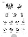
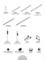
PARTS
PARTS
M-MTC4E
4-WAY FLANGE
M-MTCH
HOOK CLAMP
M-MTC4L
4-WAY LINE CLAMP
M-MTCL
JOINT
M-MTCC
TUBE CLAMP
M-MTCP
PIVOT CLAMP
M-MTCE
ELBOW
M-MTB
RUBBER BASE
M-MTCT
T-CLAMP
M-MTS02
BASE SUPPORT
(STACKABLE SYSTEM)
M-MTCF
FOOT CLAMP
M-MTCW
WALL JOINT
M-MTS03
BASE PLATE
(STACKABLE SYSTEM)

5
PARTS
M-MTA120
120 in. GUARDRAIL
AL-A0050
END CAP
VB-NM20GV
20 mm NUT
VB-BSSC3/8-BSPX1/2Z
1/2 in. CLAMPING SCREW
VB-BSSC3/8-BSPX7/8Z
7/8 in. CLAMPING SCREW
M-MTA45
45 in. TUBE FOR 1 BASE
(STANDARD SYSTEM)
M-MTA60
60 in. TUBE FOR 2 BASES
(STANDARD SYSTEM)
M-MTA75
75 in. TUBE FOR 3
BASES
(STANDARD SYSTEM)
M-MTA240
240 in. GUARDRAIL
I-CAS5PIN
LOCKING-PIN
M-MLS
SPRING-LOCK
M-MTA18
18 in. END TUBE
M-MTS01
GUARDRAIL POST
(STACKABLE SYSTEM)
M-MTS04
GUARDRAIL POST
(STANDARD SYSTEM)

6
STACKABLE
SYSTEM
C/C
115 in. (294 cm)
C/C
115 in. (294 cm)
C/C
60 in. (152 cm)
Return
C/C
60 in. (152 cm)
Return
C/C
120 in. (304 cm)
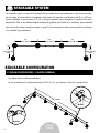
The stackable system is based on the principle that two rubber bases are stacked one on top of the other and
do not require any base tube for its installation. Each end of the structure is reinforced by the 60 in. (152 cm)
return installations as well as every 40 ft (12 m) along the guardrail line to strengthen its structure if the roof is
parapet-free. Refer to the distance diagram between the guardrail posts below for a “stackable” type installation.
Note: refer to the safety instructions section on page 2 of this document in order to comply with the conformity
of a “standard” type installation.
Use elbows when installing an end-return.
For the installation of a reinforcement return at 40 ft (12 m), use T-clamps (if the roof is parapet-free).
STACKABLE SYSTEM
1. STACKABLE CONFIGURATION - L-SHAPED GUARDRAIL
STACKABLE CONFIGURATION
40 ft (12 m)
M-MTCT
M-MTCE

7
STACKABLE
SYSTEM
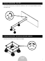
M-MTCW
3. STACKABLE CONFIGURATION - SKYLIGHTS AND ROOFLIGHTS GUARDRAIL
2. STACKABLE CONFIGURATION / WALL JOINT
M-MTCE
Use wall joints when necessary to connect the installation to a wall. Use the required hardware according
to the type of wall.
Use elbows for installation around skylights and rooflights.

8
STACKABLE
SYSTEM
4. STACKABLE CONFIGURATION - TOEBOARD
It is possible to install toeboards when necessary, in the case of a parapet-free roof, for example.
Slide the toeboards into the fittings on the bases. Fixing with screws is optional unless local regulations
state otherwise. In this case, use the required hardware.

9
STACKABLE
SYSTEM
12
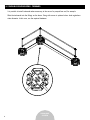
M-MTB M-MTS03
VB-NM20GV
M-MTS02
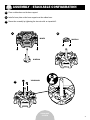
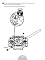
Place a rubber base on the base support.
Install a base plate on the base support over the rubber base.
Secure the assembly by tightening the two nuts with an impact drill.
1
2
3
3
ASSEMBLY - STACKABLE CONFIGURATION

10
STACKABLE
SYSTEM
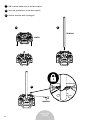
Add a second rubber base to the base support.
Insert the guardrail post on the base support.
Lock the assembly with a locking-pin.
M-MTS01
M-MTB
I-CAS5PIN
4
4
5
6
6
5

11
STACKABLE
SYSTEM
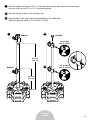
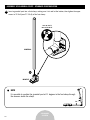
Install the middle hook clamp at 21-¼ in. (54 cm) from the ground, then install the top hook clamp
at the top of the post at 42-¼ in. (107 cm) from the ground.
Install an end cap at the top of the guardrail post.
Align the hooks of the clamps with the toeboard fitting of the rubber base.
Tighten the fastening screws to 30 lb·ft (max 37.5 lb·ft).
7
7
8
8
M-MTCH
M-MTCH
AL-A0050
9
9
21-1/4 in.
(54 cm)
42-1/4 in.
(107 cm)
REC 30 LB·FT
MAX 37.5 LB·FT
REC 30 LB·FT
MAX 37.5 LB·FT

12
STACKABLE
SYSTEM
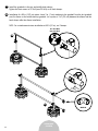
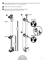
Install the guardrails in the top and middle hook clamps.
Tighten the front screws to 20 lb·ft (max 25 lb·ft) on all hook clamps.
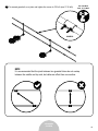
Installation of a 60 in. (152 cm) return: Leave 3 in. (7 cm) overhang to the guardrail from the last guardrail
post, fix elbows on the middle and top guardrail. Let a space of 1 in. (2.5 cm) between the elbows and the
hook clamps after the elbows installation.
NOTE: For a reinforcement return installation at 40 ft (12 m), use T-clamps.
10
11
10
11
M-MTCE
3 in.
(7 cm)
REC 20 LB·FT
MAX 25 LB·FT

13
STACKABLE
SYSTEM
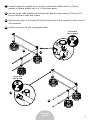
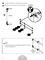
Prepare the return with a guardrail post on its bases centered in the middle of the 60 in. (152 cm)
guardrails by following assembly steps 1 to 10. Hook clamps inward.
Insert the top and middle guardrails into the elbows and tighten the clamp screws at 30 lb·ft (max 37.5
lb·ft) on each elbow to secure them in place.
Tighten the front screws to 20 lb·ft (max 25 lb·ft) of all hook clamps to fix the guardrails in place to the rest
of the installation.
Install the end caps on the ends of the guardrail returns.
12
13
14
15
13
12
15
14
REC 30 LB·FT
MAX 37.5 LB·FT
REC 20 LB·FT
MAX 25 LB·FT

14
STACKABLE
SYSTEM
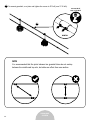
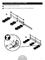
To connect guardrails, use joints and tighten the screws to 30 lb·ft (max 37.5 lb·ft).
16
16
M-MTCL
NOTE
It is recommended that the joints between two guardrail tubes do not overlap
between the middle and top rails, but rather are offset from one another.
REC 30 LB·FT
MAX 37.5 LB·FT

15
STACKABLE
SYSTEM
Install the toeboard in the base fitting.
Screw the toeboard to the base using two screws (use the required hardware).
17
17
18
18
STACKABLE CONFIGURATION - INSTALLATION OF A WOODEN TOEBOARD

16
STANDARD
SYSTEM
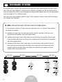
STANDARD SYSTEM
The standard system is based on the principle that the rubber bases are installed one after the other on base
tubes. Each end of the installation is reinforced by the installation of guardrail posts with two and three bases,
which are installed 39 in. (99 cm) apart according to the diagram below. Between these ends, the other guardrail
posts are installed at 78 in. (198 cm) intervals.
Note: refer to the safety instructions section on page 2 of this document in order to comply with the conformity
of a “standard” type installation.
Max. distance
39 in. (99 cm)
Max. distance
39 in. (99 cm)
Max. distance
78 in. (198 cm)
Max. distance
78 in. (198 cm)
NOTE: INSTALLATION RULES FOR TUBE CLAMPS IN RUBBER BASES
It is not essential to install two (2) tube clamps per rubber base, one (1) is sufficient if the installation
rules below are respected:
1. Installation of a single base: the tube clamp must be installed in the fitting of the base at the
opposite end of the guardrail (refer to the diagram below).
2. Installation of two bases: install a tube clamp in the closest fitting to the guardrail of the first base.
Install the second tube clamp in the fitting of the second base at the opposite end of the guardrail
(refer to the diagram below).
3. Installation of three bases: install a tube clamp in the closest fitting to the guardrail of the first
base. Install the second tube clamp in the fitting of the second base at the opposite end of the
guardrail. Install the third tube clamp in the fitting of the third base at the opposite end of the
guardrail (refer to the diagram below).
1
3
2

17
STANDARD
SYSTEM
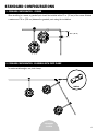
2. STANDARD CONFIGURATION - GUARDRAIL WITH PIVOT CLAMP
M-MTCP
To create variable angles, use pivot clamps.
12 in. (30 cm)
1. STANDARD CONFIGURATION - CORNER
STANDARD CONFIGURATIONS
When installing in a corner, a guardrail post should be installed within 12 in. (30 cm) of the corner. Maintain
a maximum of 78 in. (198 cm) between the guardrail posts along the installation.

18
STANDARD
SYSTEM
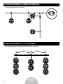
4. STANDARD CONFIGURATION - 10 FT (3 M) GUARDRAIL
B/C
60 in. (152 cm)
B/C
60 in. (152 cm)
The minimum length of a standard installation must be 10 ft (3 m).
3. STANDARD CONFIGURATION - GUARDRAIL WITH ELBOW JOINT
M-MTCE
To do a right-angled corner, use elbows.

19
STANDARD
SYSTEM
6. STANDARD CONFIGURATION - WALL JOINT
M-MTCW
5. STANDARD CONFIGURATION - TOEBOARD
M-MTCF
It is possible to install toeboards when necessary, in the case of a parapet-free roof, for example.
Fix the wooden toeboards to the foot clamps using wood screws. For the installation of aluminum toeboards,
use the required hardware.
Use wall joints when necessary to connect the installation to a wall.
Use the required hardware according to the type of wall.

20
STANDARD
SYSTEM
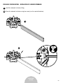
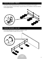
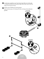
Insert a tube clamp into the fitting of the base at the opposite end of the guardrail. Make sure that
the tube clamp is at the bottom of the fitting. Only one tube clamp per base is required.
Turn the base to the side and slide the base tube into the opening of the tube clamp under the base,
taking care to let the tube stick out on one side of the base.
1
1
2
2
BASE ASSEMBLY - STANDARD CONFIGURATION
M-MTB
M-MTAXX
M-MTCC
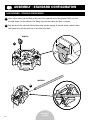
ASSEMBLY - STANDARD CONFIGURATION
M-MTCC
Page is loading ...
Page is loading ...
Page is loading ...
Page is loading ...
Page is loading ...
Page is loading ...
Page is loading ...
Page is loading ...
-
 1
1
-
 2
2
-
 3
3
-
 4
4
-
 5
5
-
 6
6
-
 7
7
-
 8
8
-
 9
9
-
 10
10
-
 11
11
-
 12
12
-
 13
13
-
 14
14
-
 15
15
-
 16
16
-
 17
17
-
 18
18
-
 19
19
-
 20
20
-
 21
21
-
 22
22
-
 23
23
-
 24
24
-
 25
25
-
 26
26
-
 27
27
-
 28
28


MetalTech Stackable System User manual
- Type
- User manual
- This manual is also suitable for
Ask a question and I''ll find the answer in the document
Finding information in a document is now easier with AI
Related papers


Other documents
-
Guardian Parapet Clamp Guardrail System Operating instructions
-
-
-
-
 SAYFA SYSTEMS UK SENTRY GW376 User manual
-
EIGER 500 3T Access Tower Installation guide
-
-
-
-
 Tall Guardrail Brace TGB-002 Installation guide

