Chief JHS210B Installation guide
- Category
- Wall & ceiling mounts accessories
- Type
- Installation guide
This manual is also suitable for

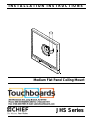
INSTALLATION INSTRUCTIONS
Instrucciones de instalación
Installationsanleitung
Instruções de Instalação
Istruzioni di installazione
Installatie-instructies
Instructions d´installation
Medium Flat Panel Ceiling Mount
Spanish Product Description
German Product Description
Portuguese Product Description
Italian Product Description
Dutch Product Description
French Product Description
JHS Series

JHS Series Installation Instructions
2
DISCLAIMER
Milestone AV Technologies, Inc., and its affiliated corporations
and subsidiaries (collectively, "Milestone"), intend to make this
manual accurate and complete. However, Milestone makes no
claim that the information contained herein covers all details,
conditions or variations, nor does it provide for every possible
contingency in connection with the installation or use of this
product. The information contained in this document is subject
to change without notice or obligation of any kind. Milestone
makes no representation of warranty, expressed or implied,
regarding the information contained herein. Milestone assumes
no responsibility for accuracy, completeness or sufficiency of
the information contained in this document.
Chief® and Centris™ are registered trademarks of Milestone
AV Technologies, Inc. All rights reserved.
IMPORTANT SAFETY INSTRUCTIONS
WARNING: A WARNING alerts you to the possibility of
serious injury or death if you do not follow the instructions.
CAUTION: A CAUTION alerts you to the possibility of
damage or destruction of equipment if you do not follow the
corresponding instructions.
WARNING: Failure to read, thoroughly understand, and
follow all instructions can result in serious personal injury,
damage to equipment, or voiding of factory warranty! It is the
installer’s responsibility to make sure all components are
properly assembled and installed using the instructions
provided.
WARNING: Failure to provide adequate structural strength
for this component can result in serious personal injury or
damage to equipment! It is the installer’s responsibility to
make sure the structure to which this component is attached
can support five times the combined weight of all equipment.
Reinforce the structure as required before installing the
component.
WARNING: Use this mounting system only for its intended
use as described in these instructions. Do not use
attachments not recommended by the manufacturer.
WARNING: Exceeding the weight capacity can result in
serious personal injury or damage to equipment! It is the
installer’s responsibility to make sure the combined weight of
all components located within the mounting system of the
JHS Series model does not exceed maximum weights listed
in table below.
WARNING: Never operate this mounting system if it is
damaged. Return the mounting system to a service center for
examination and repair.
WARNING: Do not use this product outdoors.
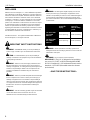
IMPORTANT ! : The JHS is designed to be installed to
one or two 1-1/2" NPT or NPSM following ANSI/ASME
B1.20.1 (Schedule 40, 0.154" minimum thickness steel or
aluminum - ASTM B221) threaded extension columns
(not included).
--SAVE THESE INSTRUCTIONS--
MODEL Max Weight
Allowed for
Display
Max Weight
Capacity of
Entire Mounting
System
JHS Series with
one column
attached 75 lbs (34.0 kg) 500 lbs (226.8 kg)
JHS Series with
two columns
attached 75 lbs (34.0 kg) 500 lbs (226.8 kg)

Installation Instructions JHS Series
3
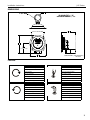
DIMENSIONS
LEGEND
6.59
167.3
6.00
152.4
3.59
C/L OF VESA PATTERN
91.1
100 mm VESA PATTERN
5.05
128.3
UP-DOWN TILT +/- 15°
LEFT-RIGHT SWIVEL +/- 75°
R1.25
31.8
1-1/2" NPS
DIMENSIONS: [MILLIMETERS]
INCHES
Tighten Fastener
Apretar elemento de fijación
Befestigungsteil festziehen
Apertar fixador
Serrare il fissaggio
Bevestiging vastdraaien
Serrez les fixations
Loosen Fastener
Aflojar elemento de fijación
Befestigungsteil lösen
Desapertar fixador
Allentare il fissaggio
Bevestiging losdraaien
Desserrez les fixations
Phillips Screwdriver
Destornillador Phillips
Kreuzschlitzschraubendreher
Chave de fendas Phillips
Cacciavite a stella
Kruiskopschroevendraaier
Tournevis à pointe cruciforme
Hex-Head Wrench
Llave de cabeza hexagonal
Sechskantschlüssel
Chave de cabeça sextavada
Chiave esagonale
Zeskantsleutel
Clé à tête hexagonale

JHS Series Installation Instructions
4
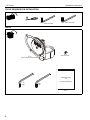
TOOLS REQUIRED FOR INSTALLATION
PARTS
3/16" (included) 5/32" (included)
A (1)
[JHS ceiling mount assembly]
B (2)
5/16-18 x 3/8"
C (1)
3/16" D (1)
5/32"
Interface Bracket
Kit
(including hardware)
E (1)

Installation Instructions JHS Series
5
INSTALLATION
IMPORTANT ! : These installation instructions assume
that a 1-1/2" NPT or NPSM following ANSI/ASME
B1.20.1 (Schedule 40, 0.154" minimum thickness steel or
aluminum - ASTM B221) threaded extension column (not
included) has been properly installed and is in place.
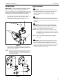
1. Thread mount (A) onto 1-1/2" NPT pipe (not included) until
hand tight, with a minimum of four threads engaged.
2. Adjust mount (A) position until Centris cup is facing the
desired position of the display. (See Figure 1)
Figure 1
3. When mount (A) is properly positioned, secure mount to
1-1/2" NPT pipe by installing and tightening 5/16-18 x 3/8"
set screw (B). (See Figure 2)
NOTE: If mount is being used to couple two pipes, use both set
screws (B) when securing mount (A) to pipes, and
ensure that both pipes are installed with a minimum of
four threads engaged.
Figure 2
Display Installation
WARNING: IMPROPER INSTALLATION CAN LEAD TO
EQUIPMENT FALLING CAUSING SERIOUS PERSONAL
INJURY AND DAMAGE TO EQUIPMENT! DO NOT
substitute hardware. Use only hardware supplied by
manufacturer!
WARNING: IMPROPER INSTALLATION CAN LEAD TO
ELECTRIC SHOCK OR DAMAGE TO EQUIPMENT! Screw
length must not exceed the depth of threaded mounting insert
in display.
WARNING: OVER-TIGHTENING OF SCREWS CAN
DAMAGE PARTS AND LEAD TO SERIOUS PERSONAL
INJURY AND DAMAGE TO EQUIPMENT! DO NOT over
tighten screws when installing interface bracket.
NOTE: If the display being installed has a 100x100 VESA
mounting pattern, no interface bracket is required and
the display can be mounted directly to the Centris cup
as outlined below.
NOTE: If the display being installed requires an interface
bracket, refer to the interface bracket installation
instructions.
WARNING: IMPROPER INSTALLATION CAN LEAD TO
DISPLAY FALLING CAUSING SERIOUS PERSONAL
INJURY OR DAMAGE TO EQUIPMENT! Using screws of
improper size may damage your display! Proper screws will
easily and completely thread into display mounting holes.
Ensure that screws are not too long.
1
1-1/2" NPT Pipe
Centris Cup
(A)
(A)
2
(A)
(B)
(C)
(B)
(C)

JHS Series Installation Instructions
6
WARNING: IMPROPER INSTALLATION CAN LEAD TO
DISPLAY FALLING CAUSING SERIOUS PERSONAL
INJURY OR DAMAGE TO EQUIPMENT! Inadequate thread
engagement in display may cause display to fall! Back out
screws ONLY as necessary to allow installation of Centris
cup!
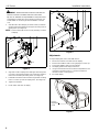
1. Start two M4 x 8mm Phillips pan head screws (included in
interface bracket hardware kit) into upper mounting holes in
display back. (See Figure 3)
NOTE: Leave at least 1/8" of each screw protruding out back
of display.
Figure 3
2. Align two screws in display back with upper mounting holes
in Centris cup and lower display until screws are seated in
lower area of teardrop mounting holes. (See Figure 4)
3. Install two more of the same screws through lower mounting
holes in Centris cup and into display back. (See Figure 4)
4. Tighten all hardware.
5. Route cables and wires to display.
Figure 4
Adjustments
To adjust display Roll, Pitch, and YAW tension:
1. Disconnect all wires and cable from the display.
2. Remove two Lower screws securing display to Centris cup.
3. Loosen two Upper screws securing display.
4. Lift display upward and away from mount.
5. Using a hex head wrench turn the tension adjustment screw
clockwise to increase tension, or counter-clockwise to
decrease tension. (See Figure 5)
6. Re-install display.
Figure 5
x 2
1
x 2
2
3
Tension
adjustment
screw

Installation Instructions JHS Series
7

JHS Series Installation Instructions
Chief Manufacturing, a products division
of Milestone AV Technologies
8800-002503 Rev00
2013 Milestone AV Technologies, a
Duchossois Group Company
www.chiefmfg.com
11/13
USA/International A 6436 City West Parkway, Eden Prairie, MN 55344
P800.582.6480 / 952.225.6000
F877.894.6918 / 952.894.6918
Europe A Franklinstraat 14, 6003 DK Weert, Netherlands
P+31 (0) 495 580 852
F+31 (0) 495 580 845
Asia Pacific A Office No. 1 on 12/F, Shatin Galleria
18-24 Shan Mei Street
Fotan, Shatin, Hong Kong
P852 2145 4099
F852 2145 4477
-
 1
1
-
 2
2
-
 3
3
-
 4
4
-
 5
5
-
 6
6
-
 7
7
-
 8
8


Chief JHS210B Installation guide
- Category
- Wall & ceiling mounts accessories
- Type
- Installation guide
- This manual is also suitable for
Ask a question and I''ll find the answer in the document
Finding information in a document is now easier with AI
Related papers
-
Chief JHSUB Installation guide
-
-
Chief JPPUB Installation guide
-
-
-
-
-
-
-
Chief JWDUS Datasheet