
EV130
EV200
EV240
EV300
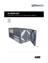
EV SERIES ERV
Installation, Operation and Maintenance Manual
Model: EV200 & EV240 Model: EV130
Model: EV300

1.800.627.44992
EV130, EV200, EV240, and EV300
ERV
There is no known safe level of cigarette smoke. Any venti-
lation system may provide noticeable improvement in spaces
where cigarettes are smoked, but it cannon be expected to
protect against the severe long-term health hazards of expo-
sure to cigarette smoke.
WARNING
Provide Adequate Service Access for Maintenance
The unit will require regular filter and core inspections. Install
the unit where you can access the core for cleaning and
replacing the filters, and where you can get at the wiring for
installation and service.
CAUTION
1. To avoid motor bearing damage and noise and/or unbal-
anced impellers, keep drywall spray, construction dust, etc.,
out of unit.
2. Do not connect power to the units external control terminals:
this will damage the unit. The external terminals are for
use only with unpowered controls designed for low-voltage
operation.
CAUTION
Risk of Fire, Electric Shock, or Injury. Observe all Codes
and the following:
1. Before servicing or cleaning the unit, unplug the line cord.
make sure unit is not running before opening its door.
2. This installation manual shows the suggested installation
method. Additional measures may be required by local codes
and standards.
3. Installation work and electrical wiring must be done by qual-
ified professional(s) in accordance with all applicable codes,
standards, and licensing requirements.
4. Any structural alterations necessary for installation must
comply with all applicable building, health, and safety code
requirements.
5. Connect this unit only to a 120 VAC grounded receptacle
protected by a 15 or 20 amp circuit breaker. Do not remove
the unit's line cord.
6. Do not install unit or controls where they can be reached
from a tub or shower.
7. This unit must be properly ducted to the outdoors.
8. Outside air inlet for this unit must be located away from
sources of hazardous air such as auto exhausts.
9. Sufficient air is needed for proper combustion and exhaust-
ing of gases through the flue (chimney) of fuel burning
equipment that might be installed in the area affected by
this equipment. If this unit is exhausting air from a space in
which chimney-vented fuel burning equipment is located,
take steps to assure that combustion air supply is not affect-
ed. Follow the heating equipment manufacturer's require-
ments of applicable codes and standards.
10. This unit is intended for general ventilating only. Do not use
to exhaust hazardous or explosive materials and vapors.
Do not connect this unit to range hoods, fume hoods, or
collection systems for toxics.
11. When cutting or drilling into wall or ceiling, do not damage
electrical wiring and other hidden utilities.
12. Use the unit only in the manner intended by the manufac-
turer. If you have questions, contact the manufacturer.
WARNING
Do not remove or disable the wiring interconnection
between the Overload Relays and the Contactors. Without
this inter-connection the motor(s) will not be protected
against overload.
CAUTION
DO NOT WASH THE ENERGY EXCHANGE CORE.
Keep it away from water or fire to avoid damaging it. Always
handle the core carefully.
CAUTION

31.800.627.4499
EV130, EV200, EV240, and EV300 ERV
Record information as shown below. In the unlikely event that factory assistance is ever
required, this information will be needed.
ERV Model:
Locate the RenewAire unit label, to be found outside of the appliance. Record the model and
serial numbers below.
NOTE: This information is for purposes of identifying the specific air handling appliance. Unit-
specific option data can then be obtained, as needed, from the Model Number.
UNIT INFORMATION
EV130
EV240
NOTE: This page
is to be completed
by the installing
contractor. The completed
document is to be turned
over to the owner after
start-up.
LABEL SIZE: 4" X 6"
LABEL STOCK: ZEBRA
TECHNOLOGIES "Z-ULTIMATE
3000 WHITE";
ZEBRA 5095 THERMAL
TRANSFER RIBBON INK.
MATERIAL:
FINISH:
LINEAR ±
HOLE SIZE ±
< ±
SURFACE FINISH
UNLESS OTHERWISE SPECIFIED, DIMENSIONS
AND TOLERANCES ARE IN INCHES.
4510 Helgesen Dr.
Madison, WI 53718 USA
FAX: (608) 221-2824
TEL: (608) 221-4499
SIZE:
TOLL FREE: (800) 627-4499
CHECKED BY: DATE:
DRAWN BY: DATE:
RenewAire
DO NOT SCALE DRAWING. REMOVE
ALL BURRS. BREAK SHARP EDGES.
APPLICABLE STANDARDS: DIM. AND
TOL. ANSI Y14.5
TITLE:
DRAWING NO.
SCALE:
REVISION
SHEET:
LEVEL DESCRIPTION DATE BY
_005_D02 Change French KMC
4/21/15
3 DEG
.005
.015
63
Z-ULTI 3000 WHITE
SEE MATERIAL
MF
CW
LABEL SERIAL-UL-EV200 RENEWAIRE
10/02/06 103512_005_D02
1/1 A1 OF 1
HVI CERTIFIED RATINGS:
FOR G5 CORE, PARAMETERS
SHOWN, PER HVI WEBSITE 1/1/11.
HVI LOGO INCLUDES "TM".
SERIAL NUMBER FORMAT: EIGHT CHARACTERS.
1ST CHARACTER INDICATES MONTH ("D" = APRIL).
2ND & 3RD DIGITS INDICATE YEAR ("15" = 2015).
FOLLOWING FOUR DIGITS ARE SERIAL NUMBERS, ENDING
WITH "R" TO SIGNIFY RESIDENTIAL UNIT.
EVERY EIGHT-DIGIT SERIAL NUMBER MUST BE UNIQUE -- NO
DUPLICATES, EVEN ACROSS MODELS.
UNIT INFORMATION
UNIT LABEL (TYPICAL)
OWNER INFORMATION
SAVE THIS MANUAL
Information that is recorded is specific to just one ERV. If additional ERVs are being
documented, please make copies of these pages and identify each copy by its unit tag.
NOTICE
EV200
EV300
Serial Number:

1.800.627.44994
RENEWAIRE.COM 1.800.627.4499 1716 FOR THE MOST COMPLETE AND CURRENT INFORMATION VISIT RENEWAIRE.COM
SPECIFICATIONS & DIMENSIONS
Specifications may be subject to change without notice.
INDOOR UNIT SPECIFICATIONS
Ventilation Type:
Static plate, heat and humidity transfer
Typical Airflow Range: 50-140 CFM
Unit is HVI Tested/Certified per CSA C439
Protocol: Using one L-50-G5 Core
Standard Features:
White painted cabinet
Line-cord power supply
Low-voltage circuit for controls
Unit may be mounted in any orientation
Cross-core differential pressure ports
Controls:
Onboard 24 VAC transformer/relay package
with switched dry contacts
Filters:
Total qty. 2, MERV 8, spun-polyester media:
10 1/2" x 10 1/2" x 1"
Unit Dimensions & Weight:
33 1/2" L x 13 1/4" W x 20" H
48 lbs.
Max. Shipping Dimensions & Weight (in carton):
32" L x 22" W x 18" H
60 lbs.
Motor(s):
Qty. 1, Double-shaft standard motor
Accessories:
Backdraft damper 6", 8"
Automatic balancing damper 4", 5", 6"
Louvered wall vent 6" - white, brown
Digital time clock - wall mount (TC7D-W),
in exterior enclosure (TC7D-E)
Carbon dioxide sensor/control - wall mount (CO2-W),
duct mount (CO2-D)
IAQ sensor - wall mount (IAQ-W), duct mount (IAQ-D)
Motion occupancy sensor/control -
ceiling mount (MC-C), wall mount (MC-W)
Percentage timer control (PTL)
Push-button point-of-use controls (PBL), PTL req’d.
Percentage timer control with furnace interlock (FM)
Dehumidistat control (DH24)
MERV 13 filter - OA airstream (shipped loose)
Electric duct heater - RH series (1-5 kW);
designed for indoor ductwork installation only
ELECTRICAL DATA
HP Volts HZ Phase Input Watts FLA
0.1 120 60 Single 102 @ 130 CFM 1.3
CORE PERFORMANCE
Airflow CFM Temp EFF% Total EFF%
Winter/Summer*
78 78 73/59
104 75 69/54
125 72 66/50
136 71 64/48
153 68 61/45
163 67 59/42
Note: Indirect Gas-Fired Duct Furnace is not available on the EV130.
130EV Energy Recovery Ventilator
Standard
Download specification at:
renewaire.com/specifications
6" Typ.
8 1/8"
6" Typ.
9"
OA
EA
RA
FA
34" Line Cord
Pressure Ports
(4) Typ.
28 3/4" Case
31" Typ.
13 1/2" Overall
4 1/8" Typ.
2 1/4" Typ.
33 1/4" Overall
6 3/8"
18 1/8"
Case
2 5/8"
7/8"
8"
Nominal
Typ.
21 3/4" Overall
(with Hanging
Bracket)
6"
Nominal
Typ.
20" Overall
12 7/8"
Case
11 1/4" Minimum
Service Area
(Door can be
Removed from
Hinges.)
18 1/2"
Minimum
Service Area
17 1/2"
Door
Swing
24V AC
Control
Terminal
LEFT VIEW
FRONT VIEW
RIGHT VIEW
TOP VIEW
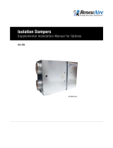
Model: EV130
Drawing Type: Unit Dimension
Version: JUN18
ABBREVIATIONS
EA: Exhaust Air to outside
OA: Outside Air intake
RA: Room Air to be exhausted
FA: Fresh Air to inside
INSTALLATION ORIENTATION
Unit may be installed in any
orientation.
NOTE
1.UNLESS OTHERWISE SPECIFIED,
DIMENSIONS ARE ROUNDED TO THE
NEAREST EIGHTH OF AN INCH.
2.SPECIFICATIONS MAY BE SUBJECT
TO CHANGE WITHOUT NOTICE.
6" Typ.
8 1/8"
6" Typ.
9"
OA
EA
RA
FA
34" Line Cord
Pressure Ports
(4) Typ.
28 3/4" Case
31" Typ.
13 1/2" Overall
4 1/8" Typ.
2 1/4" Typ.
33 1/4" Overall
6 3/8"
18 1/8"
Case
2 5/8"
7/8"
8"
Nominal
Typ.
21 3/4" Overall
(with Hanging
Bracket)
6"
Nominal
Typ.
20" Overall
12 7/8"
Case
11 1/4" Minimum
Service Area
(Door can be
Removed from
Hinges.)
18 1/2"
Minimum
Service Area
17 1/2"
Door
Swing
24V AC
Control
Terminal
LEFT VIEW
FRONT VIEW
RIGHT VIEW
TOP VIEW
Model: EV130
Drawing Type: Unit Dimension
Version: JUN18
ABBREVIATIONS
EA: Exhaust Air to outside
OA: Outside Air intake
RA: Room Air to be exhausted
FA: Fresh Air to inside
INSTALLATION ORIENTATION
Unit may be installed in any
orientation.
NOTE
1.UNLESS OTHERWISE SPECIFIED,
DIMENSIONS ARE ROUNDED TO THE
NEAREST EIGHTH OF AN INCH.
2.SPECIFICATIONS MAY BE SUBJECT
TO CHANGE WITHOUT NOTICE.
UNIT DIMENSIONS
AIRFLOW ORIENTATION
Available as shown in dimension drawing.
UNIT MOUNTING & APPLICATION
Can be mounted in any orientation. RA/EA airstream
can be switched with OA/FA airstream.
UNIT PERFORMANCE
Airflow CFM ESP in H20
78 0.60
104 0.50
125 0.40
136 0.30
153 0.20
163 0.10
Note: These are core-only ratings and are not HVI certified.
HVI ratings apply to complete units only.
See HVI certification ratings on pg. 30 of Single/Multi-Family Catalog.
Specifications may be subject
to change without notice.

51.800.627.4499
RENEWAIRE.COM 1.800.627.4499 1716 FOR THE MOST COMPLETE AND CURRENT INFORMATION VISIT RENEWAIRE.COM
Specifications may be subject to change without notice.
EV & GR-SERIES
SPECIFICATIONS & DIMENSIONS
INDOOR UNIT SPECIFICATIONS
Ventilation Type:
Static plate, heat and humidity transfer
Typical Airflow Range: 100-200 CFM
Unit is HVI Tested/Certified per CSA C439
Protocol: Using one L-100-G5 Core
Standard Features:
White painted cabinet
Line-cord power supply
Low-voltage circuit for controls
Unit may be mounted in any orientation
Cross-core differential pressure ports
Controls:
Onboard 24 VAC transformer/relay package
with switched dry contacts
Filters:
Total qty. 2, MERV 8, spun-polyester media:
10 1/2" x 21 3/4" x 1"
Unit Dimensions & Weight:
33 1/2" L x 24" W x 20" H
68 lbs.
Max. Shipping Dimensions & Weight (on pallet):
34" L x 44" W x 34" H
110 lbs.
Motor(s):
Qty. 1, Double-shaft standard motor
Accessories:
Backdraft damper 6", 8"
Automatic balancing damper 4", 5", 6"
Louvered wall vent 6" - white, brown
Louvered wall vent 8" - taupe vinyl, galvanized,
paintable galvanneal
Louvered wall vent with 8" round duct connection -
12" W x 8" H
Digital time clock - wall mount (TC7D-W),
in exterior enclosure (TC7D-E)
Carbon dioxide sensor/control - wall mount (CO2-W),
duct mount (CO2-D)
IAQ sensor - wall mount (IAQ-W), duct mount (IAQ-D)
Motion occupancy sensor/control -
ceiling mount (MC-C), wall mount (MC-W)
Percentage timer control (PTL)
Push-button point-of-use controls (PBL), PTL req’d.
Percentage timer control with furnace interlock (FM)
Dehumidistat control (DH24)
MERV 13 filter - OA airstream (shipped loose)
Electric duct heater - RH series (1-6 kW);
designed for indoor ductwork installation only
200EV Energy Recovery Ventilator
Standard
Download specification at:
renewaire.com/specifications
Note: Indirect Gas-Fired Duct Furnace is not available on the EV200.
6"
Typ.
8 1/8"
9"
5 1/2"
Typ.
OA
EA
RA
FA
34" Line Cord
Pressure Ports
(4) Typ.
24 3/8" Overall
(with Hanging
Bracket)
11 7/8"
Typ.
28 3/4" Case
33 1/4" Overall
2 1/4" Typ.
6" Nominal
Typ.
8" Nominal
Typ.
18 1/8"
Case
2 5/8"
7/8" Typ.
21 3/4" Overall
(with Hanging Bracket)
20" Overall
22 1/4" Minimum
Service Area
(Door can be
Removed from
Hinges.)
18 1/2"
Minimum
Service Area
23 7/8" Case
Door
Swing
24V AC
Control
Terminal
LEFT VIEW
FRONT VIEW
RIGHT VIEW
TOP VIEW
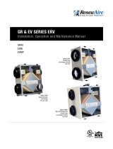
Model: EV200
Drawing Type: Unit Dimension
Version: JUN18
ABBREVIATIONS
EA: Exhaust Air to outside
OA: Outside Air intake
RA: Room Air to be exhausted
FA: Fresh Air to inside
INSTALLATION ORIENTATION
Unit may be installed in any
orientation.
NOTE
1.UNLESS OTHERWISE SPECIFIED,
DIMENSIONS ARE ROUNDED TO THE
NEAREST EIGHTH OF AN INCH.
2.SPECIFICATIONS MAY BE SUBJECT
TO CHANGE WITHOUT NOTICE.
UNIT DIMENSIONS
AIRFLOW ORIENTATION
Available as shown in dimension drawing.
UNIT MOUNTING & APPLICATION
Can be mounted in any orientation. RA/EA airstream
can be switched with OA/FA airstream.
6"
Typ.
8 1/8"
9"
5 1/2"
Typ.
OA
EA
RA
FA
34" Line Cord
Pressure Ports
(4) Typ.
24 3/8" Overall
(with Hanging
Bracket)
11 7/8"
Typ.
28 3/4" Case
33 1/4" Overall
2 1/4" Typ.
6" Nominal
Typ.
8" Nominal
Typ.
18 1/8"
Case
2 5/8"
7/8" Typ.
21 3/4" Overall
(with Hanging Bracket)
20" Overall
22 1/4" Minimum
Service Area
(Door can be
Removed from
Hinges.)
18 1/2"
Minimum
Service Area
23 7/8" Case
Door
Swing
24V AC
Control
Terminal
LEFT VIEW
FRONT VIEW
RIGHT VIEW
TOP VIEW
Model: EV200
Drawing Type: Unit Dimension
Version: JUN18
ABBREVIATIONS
EA: Exhaust Air to outside
OA: Outside Air intake
RA: Room Air to be exhausted
FA: Fresh Air to inside
INSTALLATION ORIENTATION
Unit may be installed in any
orientation.
NOTE
1.UNLESS OTHERWISE SPECIFIED,
DIMENSIONS ARE ROUNDED TO THE
NEAREST EIGHTH OF AN INCH.
2.SPECIFICATIONS MAY BE SUBJECT
TO CHANGE WITHOUT NOTICE.
CORE PERFORMANCE
Airflow CFM Temp EFF% Total EFF%
Winter/Summer*
121 81 77/64
148 79 75/61
167 78 73/59
176 78 72/58
186 77 72/58
191 77 71/57
206 76 70/56
ELECTRICAL DATA
HP Volts HZ Phase Input Watts FLA
0.1 120 60 Single 157 @ 181 CFM 1.5
UNIT PERFORMANCE
Airflow CFM ESP in H20
121 0.70
148 0.60
167 0.50
176 0.40
186 0.30
191 0.20
206 0.10
Note: These are core-only ratings and are not HVI certified.
HVI ratings apply to complete units only.
See HVI certification ratings on pg. 31 of Single/Multi-Family Catalog.
Specifications may be subject
to change without notice.

1.800.627.44996
RENEWAIRE.COM 1.800.627.4499 1918 FOR THE MOST COMPLETE AND CURRENT INFORMATION VISIT RENEWAIRE.COM
SPECIFICATIONS & DIMENSIONS
Specifications may be subject to change without notice.
240EV Energy Recovery Ventilator
Standard
INDOOR UNIT SPECIFICATIONS
Ventilation Type:
Static plate, heat and humidity transfer
Typical Airflow Range: 100-240 CFM
Unit is HVI Tested/Certified per CSA C439
Protocol: Using one L-100-G5 Core
Standard Features:
White painted cabinet
Line-cord power supply
Low-voltage circuit for controls
Unit may be mounted in any orientation
Cross-core differential pressure ports
Controls:
Onboard 24 VAC transformer/relay package
with switched dry contacts
Filters:
Total qty. 2, MERV 8, spun-polyester media:
10 1/2" x 21 3/4" x 1"
Unit Dimensions & Weight:
33 1/2" L x 24" W x 20" H
70 lbs.
Max. Shipping Dimensions & Weight (on pallet):
34" L x 44" W x 34" H
112 lbs.
Motor(s):
Qty. 1, Double-shaft standard motor
Accessories:
Backdraft damper 6", 8"
Automatic balancing damper 4", 5", 6"
Louvered wall vent 6" - white, brown
Louvered wall vent 8" - taupe vinyl, galvanized,
paintable galvanneal
Louvered wall vent with 8" round duct connection -
12" W x 8" H
Digital time clock - wall mount (TC7D-W),
in exterior enclosure (TC7D-E)
Carbon dioxide sensor/control - wall mount (CO2-W),
duct mount (CO2-D)
IAQ sensor - wall mount (IAQ-W), duct mount (IAQ-D)
Motion occupancy sensor/control -
ceiling mount (MC-C), wall mount (MC-W)
Percentage timer control (PTL)
Push-button point-of-use controls (PBL), PTL req’d.
Percentage timer control with furnace interlock (FM)
Dehumidistat control (DH24)
MERV 13 filter - OA airstream (shipped loose)
Electric duct heater - RH series (1-8 kW);
designed for indoor ductwork installation only
Download specification at:
renewaire.com/specifications
Note: Indirect Gas-Fired Duct Furnace is not available on the EV240.
5 5/8" 8 3/8"
9"
5 1/2"
Typ.
6"
OA
RA
FA
34" Line Cord
EA
Pressure Ports
(4) Typ.
24 3/8" Overall
(with Hanging
Bracket)
11 7/8"
Typ.
28 3/4" Case
33 1/4" Overall
2 1/4" Typ.
6" Nominal
Typ.
8" Nominal
Typ.
18 1/8"
Case
2 5/8"
7/8" Typ.
21 3/4" Overall
(with Hanging Bracket)
20" Overall
22 1/4" Minimum
Service Area
(Door can be
Removed from
Hinges.)
18 1/2"
Minimum
Service Area
23 7/8" Case
Door
Swing
24V AC
Control
Terminal
LEFT VIEW
FRONT VIEW
(HANGING BRACKET REMOVED FOR CLARITY)
RIGHT VIEW
TOP VIEW
Model: EV240
Drawing Type: Unit Dimension
Version: JUN18
ABBREVIATIONS
EA: Exhaust Air to outside
OA: Outside Air intake
RA: Room Air to be exhausted
FA: Fresh Air to inside
INSTALLATION ORIENTATION
Unit may be installed in any
orientation.
NOTE
1.UNLESS OTHERWISE SPECIFIED,
DIMENSIONS ARE ROUNDED TO THE
NEAREST EIGHTH OF AN INCH.
2.SPECIFICATIONS MAY BE SUBJECT
TO CHANGE WITHOUT NOTICE.
UNIT DIMENSIONS
AIRFLOW ORIENTATION
Available as shown in dimension drawing.
UNIT MOUNTING & APPLICATION
Can be mounted in any orientation. RA/EA airstream
can be switched with OA/FA airstream.
ELECTRICAL DATA
HP Volts HZ Phase Input Watts FLA
0.2 120 60 Single 216 @ 236 CFM 3.3
CORE PERFORMANCE
Airflow CFM Temp EFF% Total EFF%
Winter/Summer*
170 78 73/59
195 76 71/57
214 75 69/55
229 74 68/54
242 73 67/52
250 73 67/52
256 73 66/51
265 72 66/50
UNIT PERFORMANCE
Airflow CFM ESP in H20
170 0.80
195 0.70
214 0.60
229 0.50
242 0.40
250 0.30
256 0.20
265 0.10
Note: These are core-only ratings and are not HVI certified.
HVI ratings apply to complete units only.
See HVI certification ratings on pg. 31 of Single/Multi-Family Catalog.
Specifications may be subject
to change without notice.

71.800.627.4499
RENEWAIRE.COM 1.800.627.4499 1918 FOR THE MOST COMPLETE AND CURRENT INFORMATION VISIT RENEWAIRE.COM
Specifications may be subject to change without notice.
EV & GR-SERIES
SPECIFICATIONS & DIMENSIONS
INDOOR UNIT SPECIFICATIONS
Ventilation Type:
Static plate, heat and humidity transfer
Typical Airflow Range: 150-300 CFM
Unit is HVI Tested/Certified per CSA C439
Protocol: Using one L-100-G5 Core
Standard Features:
White painted cabinet
Line-cord power supply
Low-voltage circuit for controls
Unit may be mounted in any orientation
Cross-core differential pressure ports
Controls:
Onboard 24 VAC transformer/relay package
with switched dry contacts
Filters:
Total qty. 2, MERV 8, spun-polyester media:
10 1/2" x 21 3/4" x 1"
Unit Dimensions & Weight:
33 3/4" L x 24" W x 20" H
72 lbs.
Max. Shipping Dimensions & Weight (on pallet):
34" L x 44" W x 34" H
115 lbs.
Motor(s):
Qty. 1, Double-shaft standard motor
Accessories:
Backdraft damper 8"
Automatic balancing damper 4", 5", 6"
Louvered wall vent 8" - taupe vinyl, galvanized,
paintable galvanneal
Louvered wall vent with 8" round duct connection -
12" W x 8" H
Digital time clock - wall mount (TC7D-W),
in exterior enclosure (TC7D-E)
Carbon dioxide sensor/control - wall mount (CO2-W),
duct mount (CO2-D)
IAQ sensor - wall mount (IAQ-W), duct mount (IAQ-D)
Motion occupancy sensor/control -
ceiling mount (MC-C), wall mount (MC-W)
Percentage timer control (PTL)
Push-button point-of-use controls (PBL), PTL req’d.
Percentage timer control with furnace interlock (FM)
Dehumidistat control (DH24)
MERV 13 filter - OA airstream (shipped loose)
Electric duct heater - RH series (1-10 kW);
designed for indoor ductwork installation only
300EV Energy Recovery Ventilator
Standard
Download specification at:
renewaire.com/specifications
Note: Indirect Gas-Fired Duct Furnace is not available on the EV300.
ELECTRICAL DATA
HP Volts HZ Phase Input Watts FLA
0.2 120 60 Single 315 @ 297 CFM 3.3
CORE PERFORMANCE
Airflow CFM Temp EFF% Total EFF%
Winter/Summer*
170 78 73/59
191 77 71/57
214 75 69/55
256 73 66/51
278 71 65/49
295 70 63/47
311 69 62/46
UNIT PERFORMANCE
Airflow CFM ESP in H20
170 1.0
191 0.9
214 0.8
256 0.7
278 0.6
295 0.5
311 0.4
Note: These are core-only ratings and are not HVI certified.
HVI ratings apply to complete units only.
See HVI certification ratings on pg. 31 of Single/Multi-Family Catalog.
UNIT DIMENSIONS
AIRFLOW ORIENTATION
Available as shown in dimension drawing.
UNIT MOUNTING & APPLICATION
Can be mounted in any orientation. RA/EA airstream
can be switched with OA/FA airstream.
5 1/2" 9 1/8"
5 3/8" 9 1/4"
OA
EA
RA
FA
34" Line Cord
Pressure Ports
(4) Typ.
9 3/4"
Typ.
28 3/4" Case
33 1/4" Overall
2 1/4" Typ.
24 3/8" Overall
(with Hanging
Bracket)
10"
Typ.
7/8" Typ.
2 5/8"
21 3/4" Overall
(with Hanging Bracket)
18 1/8"
Case
To Fit
8" Duct
Typ.
20"
Overall
23 7/8" Case
22 1/4" Minimum
Service Area
(Door can be
Removed from
Hinges.)
18 1/2"
Minimum
Service Area
Door
Swing
24V AC
Control
Terminal
LEFT VIEW
FRONT VIEW
RIGHT VIEW
TOP VIEW
Model: EV300
Drawing Type: Unit Dimension
Version: JUN18
ABBREVIATIONS
EA: Exhaust Air to outside
OA: Outside Air intake
RA: Room Air to be exhausted
FA: Fresh Air to inside
INSTALLATION ORIENTATION
Unit may be installed in any
orientation.
NOTE
1.UNLESS OTHERWISE SPECIFIED,
DIMENSIONS ARE ROUNDED TO THE
NEAREST EIGHTH OF AN INCH.
2.SPECIFICATIONS MAY BE SUBJECT
TO CHANGE WITHOUT NOTICE.
Specifications may be subject
to change without notice.

1.800.627.44998
EV130, EV200, EV240, and EV300
ERV
1.0 OVERVIEW 10
1.1 DEFINITIONS .....................................................................................................10
1.2 DESCRIPTION ....................................................................................................10
1.2.1 Purpose of an ERV System .......................................................................................................10
1.2.2 When Should You Use Your ERV ................................................................................................ 10
1.2.3 Using an ERV with Air-Conditioning ..........................................................................................10
1.2.4 Controlling Excess Humidity During Cold Weather ..................................................................... 10
2.0 UNIT PLACEMENT 10
2.1 BEFORE YOU BEGIN ...........................................................................................10
2.2 LOCATION OF THE UNIT .....................................................................................11
2.3 DUCT SIZES AND INSULATION ............................................................................ 11
2.3.1 Duct Sizes ............................................................................................................................... 11
2.4 DUCTWORK APPLICATIONS ................................................................................12
3.0 INSTALLATION 14
3.1 MOUNTING THE UNIT .........................................................................................14
3.2 INSTALLING OUTSIDE AIR AND EXHAUST AIR DUCTS ..........................................14
3.3 INSTALLING RETURN AIR DUCTS ........................................................................15
3.4 INSTALLING FRESH AIR DUCTS ..........................................................................15
3.5 CONTROLS ........................................................................................................15
3.5.1 Installing Controls .................................................................................................................... 16
4.0 OPERATION 16
4.1 STARTING UP THE UNIT .....................................................................................16
4.2 VERIFYING UNIT PERFORMANCE ........................................................................16
4.2.1 Airflow ....................................................................................................................................16
4.2.2 Use Static Taps to Measure Airflow Rates ................................................................................16
4.2.3 Use Damper to Balance Airflow to Desired Rates ...................................................................... 17
4.3 MEASURE AIRFLOW ........................................................................................... 17
4.4 MEASURING CROSS CORE STATIC PRESSURE ....................................................17
5.0 MAINTENANCE 18
5.1 TO CLEAN THE ENERGY EXCHANGE ELEMENT ....................................................18
5.2 INSPECT AND CHANGE THE FILTERS REGULARLY ................................................ 18
5.3 MOTOR MAINTENANCE ......................................................................................19
5.4 GENERAL CLEANING AND INSPECTION ...............................................................19
5.5 SERVICE PARTS .................................................................................................19
TABLE OF CONTENTS

91.800.627.4499
EV130, EV200, EV240, and EV300 ERV
Figure 2.2.0 Service Clearances .......................................................................................................11
Figure 2.4.0 Separate Room Air Pick-up—Fresh Air to Furnace Return Air Trunkline ..........................13
Figure 2.4.1 Separate Air and Fresh Air Supply, EV130 Shown ...........................................................13
Figure 2.4.2 Furnace Return Air Back into Return Air ......................................................................... 13
Figure 2.4.3 Furnace Return Air Back into Supply Air .........................................................................13
Figure 3.1.0 Mounting the ERV to a Stud Wall ....................................................................................14
Figure 3.5.0 Typical Control Schematic .............................................................................................16
Figure 4.2.0 Damper installation .......................................................................................................17
Figure 4.4.0 Airflow Diagram EV130, EV200, EV240, EV300 ..............................................................18
Figure 5.5.0 Service Parts, EV130 Shown .........................................................................................19
TABLE OF CONTENTS
TABLE OF ILLUSTRATIONS

1.800.627.449910
EV130, EV200, EV240, and EV300
ERV
1.0 OVERVIEW
1.1 DEFINITIONS
OVERVIEW
NOTE: This unit is
an Energy Recovery
Ventilator, or ERV.
It is commonly referred to
throughout this manual as
an ERV.
Energy Exchange System:
Cross flow fixed-plate enthalpic energy
exchange core: engineered, proprietary
resin-media composite. Provides both
sensible and latent heat transfer.
Access Door:
Front panel opens to provide access to
filters, blowers, and energy exchanger.
Snap latches and hinges provided for
easy service.
Insulation:
1" foil-faced EPS foam throughout.
Blower/Motor:
A single high efficiency PSC motor
directly drives two large diameter
centrifugal blowers for quiet operation.
Warranty:
Ten year limited warranty on energy
exchange core; five year limited
warranty against defects in material and
workmanship on all other components.
1.2 DESCRIPTION
1.2.1 Purpose of an ERV System
Many modern homes are built airtight for energy efficiency and comfort. The result is that
natural air infiltration rates are often too low to provide acceptable indoor air quality. The
solution is to use an ERV to remove gaseous pollutants such as odors, winter-time excess
humidity, formaldehyde, smoke, radon, vapors from cleaning products, and other chemicals.
The removal of dust and other small particles from your home is not the function of an ERV.
1.2.2 When Should You Use Your ERV?
Use your ERV when windows are closed and you need to ventilate. When the outdoor air is
warmer or cooler than comfortable, the ERV will allow a quieter, more secure home with the
windows closed and will also save energy.
1.2.3 Using an ERV with Air-Conditioning
An ERV works very well with air-conditioning, because its “enthalpy-transfer” energy-exchange
core will reduce the amount of moisture in the outside air that is brought in. ERVs are the
preferred way to ventilate while air-conditioning because it brings in less moisture than any
other ventilation method.
1.2.4 Controlling Excess Humidity During Cold Weather
When the ERV is first turned on at the beginning of the heating season (or when first installed),
it will have to run full-time for several days to reduce indoor humidity levels. A properly set
dehumidistat will do this automatically. If your control is the proportional timer type (PTL or FM),
it should be set to “100%” for several days whenever you have a problem with excess humidity
during cold weather.
2.0 UNIT PLACEMENT
2.1 BEFORE YOU BEGIN
Read all instructions before installing the unit. Also review supplemental instructions included
with any controls that will be installed. Carefully unpack and inspect the unit for shipping
damage. Open the access door and inspect inside the unit. Attach the four duct collars to the
unit with the screws provided in the plastic small-parts bag.

111.800.627.4499
EV130, EV200, EV240, and EV300 ERV
6"
Typ.
8 1/8"
9"
5 1/2"
Typ.
OA
EA
RA
FA
34" Line Cord
Pressure Ports
(4) Typ.
24 3/8" Overall
(with Hanging
Bracket)
11 7/8"
Typ.
28 3/4" Case
33 1/4" Overall
2 1/4" Typ.
6" Nominal
Typ.
8" Nominal
Typ.
18 1/8"
Case
2 5/8"
7/8" Typ.
21 3/4" Overall
(with Hanging Bracket)
20" Overall
22 1/4" Minimum
Service Area
(Door can be
Removed from
Hinges.)
18 1/2"
Minimum
Service Area
23 7/8" Case
Door
Swing
24V AC
Control
Terminal
LEFT VIEW
FRONT VIEW
RIGHT VIEW
TOP VIEW
Model: EV200
Drawing Type: Unit Dimension
Version: JUN18
ABBREVIATIONS
EA: Exhaust Air to outside
OA: Outside Air intake
RA: Room Air to be exhausted
FA: Fresh Air to inside
INSTALLATION ORIENTATION
Unit may be installed in any
orientation.
NOTE
1.UNLESS OTHERWISE SPECIFIED,
DIMENSIONS ARE ROUNDED TO THE
NEAREST EIGHTH OF AN INCH.
2.SPECIFICATIONS MAY BE SUBJECT
TO CHANGE WITHOUT NOTICE.
2.2 LOCATION OF THE UNIT
Select a location so that:
u The fresh air intake vent from the outside is placed a minimum of 10' from any other
contaminated exhaust vent, and is at least 30" long.
u The two ducts to the outside are as short and straight as possible, for the best performance
from the system. Shorter duct runs help assure that the system is balanced: the amount of
air brought in is equal to the amount of air exhausted.
u The power cord reaches an electrical outlet.
u The door can be opened to allow cleaning the core and filters. Provide at least 24" of
clearance at front of unit for service access to the blowers, filters and energy exchange core.
u The exhaust outlet and fresh air inlet on the outside of the building should be at least ten feet
apart to avoid cross-contamination. The exhaust duct should be about the same length as the
fresh air duct.
u The exhaust outlet should not dump air into an enclosed space or into any other structure.
u Do not install the exhaust outlet and fresh air inlet through the roof.
The preferred mounting location for the unit is on a concrete foundation wall because the
foundation wall will isolate any blower vibration.
If a basement area is not available or practical, use other mechanical room space such as a
closet, garage, storage, or accessible attic or crawl space.
FIGURE 2.2.0 SERVICE CLEARANCES
Provide Adequate Service
Access for Maintenance
The unit will require regular
filter and core inspections.
Install the unit where you
can access the core for
cleaning and replacing the
filters, and where you can
get at the wiring for installa-
tion and service.
CAUTION
UNIT PLACEMENT
NOTE: If you wish
to install the unit
in an attic or other
unconditioned space, you
must insulate all of the
unit’s ductwork that is
located in the attic. Use at
least R-6 insulation.
The Exhaust Air Duct and the Outside Air Duct connect the unit to the outside. Flexible insulated
duct is typically used.
2.3.1 Duct Sizes
Exhaust Air & Outside Air (EA & OA):
u EV130—6" round insulated duct, 8" round insulated duct may be used to maintain
maximum airflow.
u EV200, EV240 and EV300—8" round insulated duct recommended.
Fresh Air & Return Air (FA & RA):
u 6" round or 8" oval rigid un-insulated.
Ducts from unit to house in unconditioned spaces:
u All ducts from unit to house in unconditioned spaces like attics and crawl spaces
must be insulated.
2.3 DUCT SIZES AND INSULATION

1.800.627.449912
EV130, EV200, EV240, and EV300
ERV
UNIT PLACEMENT
2.4 DUCTWORK APPLICATIONS
u FOR HOUSES WITHOUT DUCTED HEATING OR COOLING SYSTEMS–SEE FIGURE 2.4.1.
In most houses one or two fresh air grilles in a central part of the house provide effective
distribution of the fresh air into the home, particularly when the stale exhaust air is picked
up at several points. Because the fresh air is not fully conditioned, the fresh air supply grilles
should be located in a traffic area like a hallway or stairway rather than in a sitting area.
If you want to get fresh air into specific rooms with high occupancy, you can split up the fresh
air supply.
u FOR HOUSES WITH DUCTED HEATING OR COOLING SYSTEMS–SEE FIGURES 2.4.0, 2.4.2, AND
2.4.3.
Most units are installed with the fresh air duct connected directly to a return duct for the
main heating and cooling system. Be careful to connect the fresh air duct at least three feet
from the return plenum to minimize suction from the furnace blower. A connection closer to
the furnace may result in unbalanced flow and associated problems.
u FOR INSTALLATIONS THAT COLLECT STALE AIR FROM SPECIFIC ROOMS IN THE HOME–SEE
FIGURES 2.4.0 AND 2.4.1.
Locate stale air return grilles (RA) in rooms where moisture and odors are generated:
bathrooms, the kitchen, and perhaps other areas where contaminants are generated such as
in the home workshop. Return grilles in these other areas may be dampered so that they can
be shut off when not in use. A central location such as a hallway is also acceptable but won’t
clear humidity and odors from baths and kitchens as rapidly.
Locate stale air return grilles (RA) near the ceiling on inside walls. Stale air returns are
usually easiest to install in interior partitions. Put them in the ceiling if that is easier.
u STALE AIR RETURN GRILLE SIZES (8" round on EV300)
u BATHROOM: 4" x 10" or 6" x 10"—40 to 60 sq. in.
u KITCHEN: 6" x 10"—60 sq. in.
u CAN AN ERV BE USED TO VENTILATE BATHROOMS?
A RenewAire ERV can be used as a central exhaust system in place of bathroom exhaust
fans. Tie a grille in each bathroom directly back to the ERV—see Figure 2.4.0. A successful
installation should provide at least 50 CFM of exhaust per moisture producing bathroom.
When used for bathroom exhaust, the EV130 should be used for no more than two
bathrooms, the EV200 and EV240 for up to four bathrooms and the EV300 for up to six
bathrooms. Install a control in each bathroom ventilated by the ERV.
u FOR HOUSES WHERE RADON IS A CONCERN.
The first line of defense against radon should always be techniques that prevent the entry
of radon into the home, such as under-slab suction, vented perimeter drainage, and crack
sealing. However, if moderate levels of radon continue to be present, it is important that
the unit slightly pressurize the basement, not de-pressurize the basement. Installation of
this unit for radon mitigation is beyond the scope of this manual. Consult a radon mitigation
professional.
NOTE: For all units:
RA = Room Air into
unit
OA = Outside Air into unit
SA = Supply Air to inside
EA = Exhaust Air to outside
FA = Fresh Air to inside

131.800.627.4499
EV130, EV200, EV240, and EV300 ERV
UNIT PLACEMENT
NOTE: ERV blower
may be operated
separate from
furnace blower.
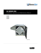
FIGURE 2.4.0 SEPARATE ROOM AIR PICK-UP—FRESH AIR TO FURNACE RETURN AIR TRUNKLINE
NOTE: The furnace
blower must be
operated any time
the ERV is operated. Use
furnace fan “on” continu-
ous low speed or optional
FM control to cycle furnace
fan on ERV.
FIGURE 2.4.2 FURNACE RETURN AIR BACK INTO RETURN AIR
NOTE: ERV blower
may be operated
separate from
furnace blower.
FIGURE 2.4.3 FURNACE RETURN AIR BACK INTO SUPPLY AIR
www.renewaire.com (800) 627- 4499 [email protected]
FIGURE 2.4.1 SEPARATE RETURN AIR AND FRESH AIR SUPPLY, EV130 SHOWN
NOTE: ERV blower
may be operated
separate from
furnace blower.

1.800.627.449914
EV130, EV200, EV240, and EV300
ERV
Foam Tape
Foam Tape
Metal Washer
Lag Screw or Concrete Anchor
(provided by others)
Lag Screw or Concrete Anchor
(provided by others)
Unit Flange
Optional Washer and Screw
(provided by others)
Hanging Bracket
INSTALLATION
3.1 MOUNTING THE UNIT
u UNIT MAY BE INSTALLED IN ANY ORIENTATION
Orient the unit for the simplest duct layout and connections.
u MOUNT THE ERV ON A CONCRETE FOUNDATION WALL
Mount hanging bracket to the wall with appropriate concrete anchors. Use pre-cut foam tape
from small parts bag. Remove backing and apply two pieces of foam tape equally spaced
along the unit’s mounting flange to be held by the hanging bracket. Apply the other two
pieces of foam over two holes that will be used for fastening, on the other flange. The tape
should be applied in a “U” shape to cushion both the front and back of the integral flanges.
Lift unit and slide unit flange into the hanging bracket. Using metal flat washers, fasten
flange opposite hanging bracket to structure. Safety screws should similarly be installed
passing through the hanging bracket and flange. Make sure the screws, which you must
supply, are properly selected for the loads and substrate involved.
u MOUNTING THE ERV TO A STUD WALL
Mount unit using supplied hanging bracket kit as described for mounting to concrete
foundation wall.
u SUSPENDING THE ERV FROM FLOOR JOISTS OR TRUSSES
The unit may be screwed directly to joists or trusses using the hanging bracket and integral
flange. Mount as described for mounting to concrete foundation wall.
3.0 INSTALLATION
FIGURE 3.1.0 MOUNTING THE ERV TO A STUD WALL
Risk of injury when lifting unit and installing it overehead. Get a helper and wear eye protection.
CAUTION
3.2 INSTALLING OUTSIDE AIR AND EXHAUST AIR DUCTS
Ducts connecting the unit to the outside must be well-insulated.
Band or tape inner duct liner to inner flange of appropriate collar. Drive a sheet metal screw
through liner to secure duct spiral wire to collar. Straighten insulation, and slide outer duct
jacket onto the outer flange of the duct collar. Secure with band or tape.
The inlets and outlets should be screened against insects and vermin and shielded from the
weather to prevent the entry of rain or snow.
The vapor barrier should
be continuous and sealed
against air and moisture
leakage! If not, condensa-
tion or ice may form in cold
weather on the duct surface
or in its insulation.
CAUTION
NOTE: The hole lay-
out on the hanging
bracket is spaced
for 16", 19.2", and 24"
on-center layouts.
NOTE: The door
is equipped with
slide-off hinges.
For the homeowner’s
convenience it is helpful
to orient the unit so that
the door does not drop off
when it is unlatched.
NOTE: The hole
layout on the
integral mounting
flanges and the hanging
bracket are spaced for 16"
or 24" on-center framing
patterns.

151.800.627.4499
EV130, EV200, EV240, and EV300 ERV
INSTALLATION
3.3 INSTALLING RETURN AIR DUCTS
All the stale air returns are connected by ducts to the unit. Generally, empty stud cavities are
used for returns as is often done with cold air returns for the furnace, using standard duct
boots to connect to six inch pipe at the bottom or top of the wall cavity. Always be sure to seal
all joints with duct sealant or tape. Some local codes may require metal ducting all the way
from the boots to the stale air grilles. Use rigid ducts to allow the air to move freely and easily
through the ducts. See Duct Sizes to size your duct work.
If duct runs are very long (over 25' of flex duct for 130 CFM or over 10' for 200 CFM each
run) or have excessive bends or elbows or if maximum airflow rates are required, eight inch
insulated flexible duct should be used. The outer flange of the duct collar can be used for both
the inner and outer jacket of the flexible duct. Care must be taken to insure that the duct is
securely fastened and sealed to the duct collar.
DO NOT USE MORE FLEX DUCT THAN NECESSARY!
Flex duct is much more resistant to airflow than rigid duct; longer runs of flex duct will reduce
the ventilation performance of your system. Stretch flex duct and avoid sharp bends.
3.4 INSTALLING FRESH AIR DUCTS
Use a five foot section of flexible insulated duct to connect the unit to the ducts at the port
labeled Fresh Air to the Inside. This will cut noise transmitted from the unit. Stretch the flex
duct tightly in order to maintain good airflow.
3.5 CONTROLS
For an installation in which the ERV should run continuously in order to provide the required
ventilation rate for the home, no controls are needed. However, in most installations, control
over the unit operation is desired and this is best provided by an optional RenewAire Percentage
Timer Control (PTL or FM).
Percentage timers (PTL or FM controls) may be located anywhere that is convenient. A typical
location for either control is next to the home’s thermostat. Percentage timers operate the ERV
to provide regular background ventilation of the home.
ERV installations that pull stale air from specific rooms, such as bathrooms, should have
optional RenewAire Push-button Lighted (PBL) Controls in those rooms. The secondary
operating controls allow the system to be turned on from various locations in the house.
Do not place any stale air
returns in garages.
CAUTION
Do not connect Dryers to
unit. Do not connect Range
Hoods to the unit.
CAUTION
Install Fresh Air Inlet Away From Sources of Contaminants.
u Do not locate the fresh air inlet where vehicles may be serviced or left idling.
u The fresh air inlet should be at least 10' away from any exhaust such as dryer vents,
chimneys, furnace and water heater exhausts, or other sources of contamination or carbon
monoxide.
u Install 12" above ground level.
u Never locate the fresh air inlet inside a structure.
CAUTION
DANGER OF ELECTRICAL SHOCK WHEN SERVICING AN INSTALLED UNIT.
Always unplug unit before connecting or servicing controls.
WARNING

1.800.627.449916
EV130, EV200, EV240, and EV300
ERV
See installation manuals for the control(s) you select for wiring diagrams and specific
instructions.
u If NOT connecting controls to the ERV:
Make a jumper out of a short piece of wire. ERV will run full-time once its power cord is
plugged in.
FIGURE 3.5.0 TYPICAL CONTROL SCHEMATIC
Up to (6) PBL Controls, wired in parallel, may be used.
ERV PTL PBL
1
Only (2) PBL Controls can be directly connected to the PTL Control.
Wire any additional PBLs in parallel with the first two.
R
C
PB
PB
PBL
2
PBL
3
OPERATION
3.5.1 Installing Controls
u Optional Controls:
RenewAire offers a variety of controls specifically designed to work with the
EV130/200/240/300 products. These include: PTL (a two wire percentage timer), FM (a six
wire percentage timer that will interconnect with the furnace blower), and PBL (point of use
push button control). Other controls that throw an unpowered switch may also be used.
u Typical Control Schematic:
Various wiring designs can be used to properly control the unit and meet safety and code
concerns. Consult your electrician for an electrical design to meet your needs.
The schematic below (Figure 3.5.0) shows a typical control system: a PTL percentage timer
plus three PBL push-button controls.
4.1 STARTING UP THE UNIT
u Inspect your installation to be sure all duct work is correctly installed and sealed, that filters
are in place, and controls (if any) are connected.
u Shut and latch the door to the unit.
u Plug unit into 115 VAC outlet. It may start immediately.
u Use control to turn on the unit. Check operation of the control(s).
u Check that the unit’s safety interlock switch turns off the unit when the door is opened.
4.0 OPERATION
4.2 VERIFYING UNIT PERFORMANCE
Do not remove or disable
the wiring interconnection
between the Overload
Relays and the Contactors.
Without this inter-
connection the motor(s)
will not be protected
against overload.
CAUTION
4.2.1 Airflow
Airflow should be occurring in both airstreams. Sometimes the easiest place to confirm that
air is moving is at the external wall caps. If exact airflow is critical, it may be desirable to
permanently install flow measuring stations and manometers. These can also be used to
determine when filters should be cleaned or changed.
4.2.2 Use Static Taps to Measure Airflow Rates
See Differential Static Across Core tables in Section 4.4 on page 18.

171.800.627.4499
EV130, EV200, EV240, and EV300 ERV
OPERATION
4.2.3 Use Damper to Balance Airflow to Desired Rates, if necessary
The ERV's blower motors are well suited for volume control by dampers on the inlet of the unit.
One balancing damper is provided in the unit parts tray.
After measuring the airflow of the unit, the balanced damper may be used to balance airflow
if desired. Place the damper between the duct collar and the unit for the inlet of the airstream
recording higher flow.
Slowly move the damper further into the duct until the desired airflow is recorded. Secure the
damper in place using 1/8" tek screws (provided).
FIGURE 4.2.0 DAMPER INSTALLATION
NOTE: The unit
is considered
balanced if the
difference between the two
airflows is not more than
10 CFM.
NOTE: Install the
damper so that
it slides from the
door of the unit down to
the duct collar.
NOTE: Drilling
through the case
while the unit is
running may cause metal
shards to be drawn into
the unit.
4.3 MEASURING AIRFLOW
4.3.1 Equipment Required
u A magnehelic gauge or other device capable of measuring 0–1.0 in. water of differential
pressure.
u 2 pieces of natural rubber latex tubing, 1/8" ID, 1/16" Wall works the best.
NOTE: Be sure to
remove cap from
pressure port
before inserting tubing.
Insure tubing is well seated
in pressure ports.
NOTE: The tubing
should extend in
the pressure port
approx. 1".
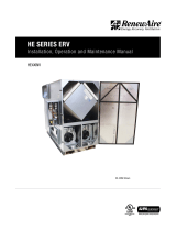
4.4 MEASURING CROSS CORE STATIC PRESSURE
The individual differential static pressures (DP) are measured using the installed pressure ports
located in the front of the units core access doors.
Do not relocate pressure ports.
u To read SCFM of Fresh Air (FA) install the “high” pressure side (+) of your measuring device
to the Outside Air (OA) port and the “low” pressure side (-) to the Fresh Air (FA) port.
u To read SCFM of Room Air (RA) install the “high” pressure side (+) of your measuring device
to the Room Air (RA) port and the “low” pressure side (-) to the Exhaust Air (EA) port.
u If gauge drops below zero, reverse tubing connections.
u Use the reading displayed on your measurement device to cross reference the CFM output
using the conversion chart.
NOTE: These
ports are carefully
located on the unit
to give the most accurate
airflow measurement.
Make sure clean filters are installed before balancing airflow. Dirty or clogged filters reduce
airflow through the unit.
CAUTION NOTE: Be sure to
replace cap into
pressure port when
airflow measuring
is completed.

1.800.627.449918
EV130, EV200, EV240, and EV300
ERV
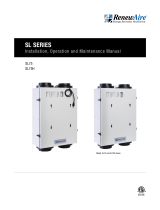
FIGURE 4.4.0 AIRFLOW DIAGRAM EV130, EV200, EV240, EV300
OA EA
RA FA
Pressure Ports
(4) Typ.
DIFFERENTIAL STATIC ACROSS CORE DSP VS. CFM
EV130
DSP 0.10 0.20 0.30 0.40 0.50
Fresh Air (FA) CFM 28 57 85 113 142
Room Air (RA) CFM 28 57 85 113 142
DIFFERENTIAL STATIC ACROSS CORE DSP VS. CFM
EV200, EV240,
EV300
DSP 0.10 0.20 0.30 0.40 0.50 .60
Fresh Air (FA) CFM 59 119+ 178 238 297 356
Room Air (RA) CFM 59 119+ 178 238 297 356
MAINTENANCE
NOTE: For best
performance the
airflow rate for
both the Fresh Air and
the Exhaust Air should
be roughly equal (“bal-
anced”). In some facilities
a slight positive or negative
pressure in the building is
desired. RenewAire ERVs
can generally operate with
a flow imbalance of up to
20% without significant
loss in energy recovery
efficiency.
The proper airflow range
for the models are:
EV130: 50–140 CFM
EV200: 100–200 CFM
EV240: 100–240 CFM
EV300: 150–300 CFM
CAUTION
Keep your ERV performing at its best by cleaning it as described below.
5.1 TO CLEAN THE ENERGY EXCHANGE ELEMENT
1. Remove the filters (see below).
2. Vacuum the exposed faces of the energy exchange core with a soft brush attachment.
3. After servicing the filters, re-install them (see below).
4. Vacuum out dust from the rest of the unit case. Dust collects only on the entering faces
of the energy exchange core. The interior of the energy exchange core stays clean even if
the core faces are dust covered. The core flutes move the air in a laminar airflow such that
particulate deposition is maintained at virtually nill.
5.0 MAINTENANCE
DO NOT WASH THE
ENERGY EXCHANGE CORE.
Keep it away from water
or fire to avoid damaging
it. Always handle the core
carefully.
CAUTION
Risk of Fire, Electric Shock,
or Injury.
u Before servicing or
cleaning the unit, unplug
the line cord.
u Make sure unit is not
running before opening its
door. Blower wheels are
sharp and can cut.
u Do not disable the
interlock switch: it is there
for your safety.
WARNING
5.2 INSPECT AND CHANGE THE FILTERS REGULARLY
Service filters every three months when the unit is in regular use or as needed to keep them
reasonably clean.
1. Release cam latches and carefully swing access door open. Remove the door by sliding to
one side.
2. Remove filter clips.
3. Pull the filters out.
4. Vacuum with a hose attachment.
5. Re-install filters and filter clips, see Section 5.5 Service Parts. Orange side of filter should
face the core.
6. Re-install door, and fasten cam latches.
The primary contact for replacement filters for your RenewAire unit is the installing contractor.
As an alternative, you may wish to produce your own filters. Please follow these instructions:

191.800.627.4499
EV130, EV200, EV240, and EV300 ERV
MAINTENANCE
Filters may be cut from a sheet or roll of ¾"–1" firm, spun polyester filter “hog hair” media or
material, similar to the existing filter in the residential unit.
The size of each filter (2 required per unit) is as follows:
EV130 10 ½" x 10 ½"
EV200/EV240/EV300 10 ½" x 21 ¾"
Call your HVAC contractor or RenewAire for further information.
NOTE: The filters
should be replaced
after they have
been cleaned
several times.
NOTE: Filters must
be used or the
face of the energy
exchange core will become
blocked by dust and
reduce unit efficacy. The
filters supplied in the unit
are usually able to keep
the energy exchange core
clean for many months.
Finer filters can be used
but must be cleaned more
often.
5.3 MOTOR MAINTENANCE
The blower/motor package needs no lubrication:
Vacuum clean the blower wheels at the same time you clean the face of the energy exchange
core. Confirm blower wheel is not rubbing against the blower inlet or housing by rotating wheel
manually.
5.4 GENERAL CLEANING AND INSPECTION
Perform general cleaning and visual inspection when changing filters.
1. Remove paper, leaves, etc. from inlet and outlet screens.
2. Inspect for insect nests.
5.5 SERVICE PARTS
FIGURE 5.5.0 SERVICE PARTS, EV130 SHOWN

About RenewAire
For over 30 years, RenewAire has been a pioneer in enhancing indoor air quality (IAQ)
in commercial and residential buildings of every size. This is achieved while maximizing
sustainability through our fifth-generation, static-plate, enthalpic-core Energy Recovery
Ventilators (ERVs) that optimize energy efficiency, lower capital costs via load reduction and
decrease operational expenses by minimizing equipment needs, resulting in significant energy
savings. Our ERVs are competitively priced, simple to install, easy to use and maintain and have
a quick payback. They also enjoy the industry’s best warranty with the lowest claims due to
long-term reliability derived from innovative design practices, expert workmanship and Quick
Response Manufacturing (QRM).
As the pioneer of static-plate core technology in North America, RenewAire is the largest ERV
producer in the USA. We’re committed to sustainable manufacturing and lessening our
environmental footprint, and to that end our Waunakee, WI plant is 100% powered by wind
turbines. The facility is also one of the few buildings worldwide to be LEED and Green Globes
certified, as well as having achieved ENERGY STAR Building status. In 2010, RenewAire joined
the Soler & Palau (S&P) Ventilation Group in order to provide direct access to the latest in energy-
efficient air-moving technologies. For more information, visit: renewaire.com
Member of the S&P Group
Family of Brands
2020 © RenewAire LLC
134777_017_NOV20
201 Raemisch Road | Waunakee, WI | 53597 | 800.627.4499 | RenewAire.com
-
 1
1
-
 2
2
-
 3
3
-
 4
4
-
 5
5
-
 6
6
-
 7
7
-
 8
8
-
 9
9
-
 10
10
-
 11
11
-
 12
12
-
 13
13
-
 14
14
-
 15
15
-
 16
16
-
 17
17
-
 18
18
-
 19
19
-
 20
20


RenewAire EV Series Owner's manual
- Type
- Owner's manual
- This manual is also suitable for
Ask a question and I''ll find the answer in the document
Finding information in a document is now easier with AI
Related papers
-
 RenewAire BR130 SERIES Quick start guide
-
 RenewAire EV130 Installation guide
-
 RenewAire CA2XIN Owner's manual
-
 RenewAire HE Series Owner's manual
-
 RenewAire GR90, EV90, & EV90P Owner's manual
-
 RenewAire HE Series Owner's manual
-
 RenewAire CA4XRT Owner's manual
-
 RenewAire SL75 Owner's manual
-
 RenewAire HE3XRTC Owner's manual
-
 RenewAire Digital Time Clock Owner's manual


