Danfoss S90 P Installation guide

Category
Car kits
Type
Installation guide

Danfoss S90 P is an advanced displacement control kit designed to enhance the performance and functionality of your hydraulic system. With its versatile capabilities, this kit offers precise control over pump displacement, enabling you to optimize system efficiency and responsiveness. The S90 P features a robust construction and meticulous design, ensuring reliable operation even in demanding conditions. Whether you're working on mobile machinery, industrial equipment, or agricultural vehicles, this kit provides a comprehensive solution for your displacement control needs.

Danfoss S90 P is an advanced displacement control kit designed to enhance the performance and functionality of your hydraulic system. With its versatile capabilities, this kit offers precise control over pump displacement, enabling you to optimize system efficiency and responsiveness. The S90 P features a robust construction and meticulous design, ensuring reliable operation even in demanding conditions. Whether you're working on mobile machinery, industrial equipment, or agricultural vehicles, this kit provides a comprehensive solution for your displacement control needs.

© Danfoss, 2014 AN00000103un-US | BLN-10031 • Rev DB • May 2016 1
Service Kit Instructions
Displacement control kits
Replacement procedure
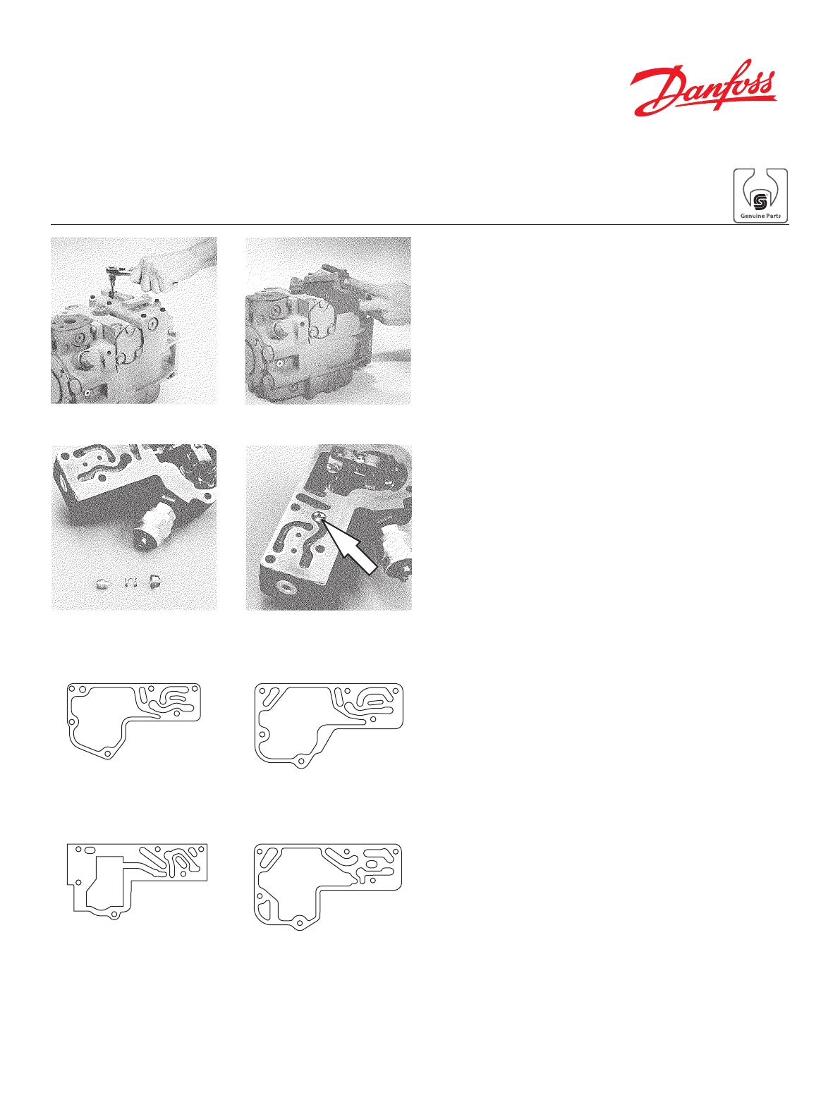
Removing and installing displacement control (MDC,
HDC, EDC)
Thoroughly clean external surfaces of pump prior to
removal of control.
Using a 5 mm internal hex wrench, remove the six (6) control
mounting screws. Remove the original control and gasket
from housing.
CAUTION
Protect exposed surfaces and cavities from damage and
foreign material.
WARNING
Failure to use the appropriate gasket may result in uncon-
trolled pump displacement.
The orice check valve is located in the inner surface of the
control assembly. Remove the spring retainer and spring
from the orice check valve cavity of the original control and
then remove the orice check valve.
NOTE: Certain controls may have orices installed in the
servo feed and drain passages of the control. If such orices
are present, they must also be transfered to the replacement
control.
Install the orice check valve in the cavity of the replacement
control and then install the spring and spring retainer to hold
the orice check valve in position.
In preparation for installing the replacement control, place a
new gasket on the housing.
Later production hydraulic displacement controls (HDCs)
use a dierent gasket from earlier production HDCs, manual
displacement controls (MDCs) and electric displacement
controls (EDCs). Refer to the accompanying illustrations for
identication.
Check that the control orice check valve, spring, and retainer
are in their proper position in the replacement control.
Fig. 1 - Remove mounting
screws
Fig. 2 - Remove control
Fig. 3 - Orice check valve
components
Fig. 4 - Orice check valve
installed
Fig. 5 - Gaskets for MDCs, EDCs and earlier production
HDCs
Fig. 6 - Gaskets for later production HDCs
75cc, 100cc,
130cc
30cc, 42cc,
55cc
30cc, 42cc,
55cc
75cc, 100cc,
130cc
© Danfoss, 2014 AN00000103un-US | BLN-10031 • Rev DB • May 2016 2
For 042 frame size pumps, the
sealing washer must be installed
under the head of this screw.
Fig. 7 - Assemble control
linkage
Fig. 8 - Location of sealing
washer for 42cc pumps
Fig. 9 - Install control
screws
Fig. 10 - Torque mounting
screws
Engage the pin on the control linkage in the mating hole in
the link attached to the swashplate. Set control into position.
Feel for pin engagement by tipping the control before install-
ing the mounting screws. The control will not tip more than
±10° if the pin is properly engaged.
WARNING
Uncontrolable vehicle or load movement will occur upon
start-up if control is installed without engagement of
control feedback link pin into swashplate link.
In case of non-engagement remove the control and repeat the
above procedure.
Torque the screws to 12 ft.lbsf. (16 Nm).
NOTE: When reinstalling the Manual Displacement Control
linkage, the control shaft nut should be torqued to 100 in.lbsf.
(11.3 Nm) MAXIMUM. If a Manual Displacement Control
equipped with a neutral start switch is being replaced, check
the operation of the switch and adjust if necessary.
WARNING
Vehicle or load movement can result from improperly
adjusted control neutral. Follow Service Manual proce-
dure for adjusting neutral” after start-up.
Always disable vehicle (wheels raised o the ground,
work function disconnected, etc.) to prevent movement
upon start-up.
  • Page 1 1
  • Page 2 2

Danfoss S90 P Installation guide

Category
Car kits
Type
Installation guide

Danfoss S90 P is an advanced displacement control kit designed to enhance the performance and functionality of your hydraulic system. With its versatile capabilities, this kit offers precise control over pump displacement, enabling you to optimize system efficiency and responsiveness. The S90 P features a robust construction and meticulous design, ensuring reliable operation even in demanding conditions. Whether you're working on mobile machinery, industrial equipment, or agricultural vehicles, this kit provides a comprehensive solution for your displacement control needs.

Ask a question and I''ll find the answer in the document

Finding information in a document is now easier with AI