Rockwell 10" Contractors' Saw User manual
- Type
- User manual

10"(254 mm)
Contractors'
~
~
~
[I
,mr
~
L
SHOWN WITH ACCESSORY
STAND AND ELECTRICALS
Part No. 4££-1 ~-ob 1-0001
@Rockwellinternational Corporation, 1983
LJated t>-l-tl~

SAFETY RULES FOR ALL TOOLS
There are also certain applications for which this tool was designed. Rockwell strongly recommends that
this tool NOT be modified and/or used for any application other than for which it was designed. If you
have any questions relative to its appl ication DO NOT use the tool until you have written Rockwell and we
have adv ised you.
ROCKWELL INTERNATIONAL
MANAGER OF PRODUCT SAFETY
POWER TOOL DIVISION
400 NORTH LEXINGTON AVENUE
PITTSBURGH, PENNSYLVANIA 15208
1. KNOW YOUR POWER TOOL. Read the owner's manual 13. SECURE WORK. Use clamps or a vise to hold work,
carefully. Learn the tools applications and limitations, as well when practical. It's safer than using your hand and frees both
as the specific potential hazards peculiar to it. hands to operate tool.
Keep your proper footing and
14. DON'T OVERREACH
balance at all times.
2. KEEP GUARDS IN PLACE and in working order
3. GROUND ALL TOOLS. If tool is equipped with three-
prong plug, it should be plugged into a three-hole electrical
receptacle. If an adapter is used to accommodate a two-prong
receptacle, the adapter lug must be attached to a known
ground. Never remove the third prong.
4. REMOVE ADJUSTING KEYS AND WRENCHES. Form
habit of checking to see that keys and adjusting wrenches are
removed from tool before turning it on.
5. KEEP WORK AREA CLEAN
benches invite accidents.
Cluttered areas and
6. AVOID DANGEROUS ENVIRONMENT. Don't use
power tools in damp or wet locations, or expose them to rain.
Keep work area well lighted.
7. KEEP CHILDREN AND VISITORS AWAY. All children
and visitors should be kept a safe distance from work area.
8. MAKE WORKSHOP KIDPROOF -with padlocks, master
switches, or by removing starter keys.
9. DON'T FORCE TOOL. It will do the job better and be
safer at the rate for which it was desigoed.
10. USE RIGHT TOOL. Don't force tool or attachment to
do a job it was not designed for.
11. WEAR PROPER APPAREL. No loose clothing, gloves,
neckties, or jewelry to get caught in moving parts. Nonslip
footwear is recommended. Wear protective hair covering to
contain long hair.
15. MAINTAIN TOOLS IN TOP CONDITION. Keep tools
sharp and clean for best and safest performance. Follow
instructions for lubricating and changing accessories.
16. DISCONNECT TOOLS before servicing and when
changing accessories such as blades, bits, cutters.
17. USE RECOMMENDED ACCESSORIES. Consult the
owner's manual for recommended accessories. The use of
improper accessories may cause hazards.
18. AVOID ACCIDENTAL STARTING. Make sure switch
is in "OFF" position before plugging in cord.
19. NEVER STAND ON TOOL. Serious injury could occur
if the tool is tipped or if the cutting tool is accidentally
contacted.
20. CHECK DAMAGED PARTS. Before further use of the
tool, a guard or other part that is damaged should be carefully
checked to ensure that it will operate properly and perform its
intended function ~ check for alignment of moving parts,
binding of moving parts, breakage of parts, mounting, and any
other conditions that may affect its operation. A guard or
other part that is damaged should be properly repaired or
replaced.
21. DIRECTION OF FEED. Feed work into a blade or cutter
against the direction of rotation of the blade or cutter only.
22. NEVER LEAVE TOOL RUNNING UNATTENDED.
TURN POWER OFF. Don't leave tool until it comes to a
complete stop.
23. DRUGS, ALCOHOL, MEDICATION. Do not oper-
ate tool while under the influence of drugs, alcohol or any
medication.
12. USE SAFETY GLASSES. Also use face or dust mask if
cutting operation is dusty.
ADDITIONAL SAFETY RULES FOR CIRCULAR SAWS
...
6. NEVER reach behind or over the cutting tOOl with
either hand for any reaspn.
3. ALWAYS use a push stick for ripping narrow StOCK.
Refer to ripping applications in instruction manual
where push stick is covered in detail.
7. MOVE the rip fence out of the way when cross
cutting.
2
As with all power tools there is a certain amount of hazard involved with the operator and his use ot the
tool. Using the tool with the respect and caution demanded as far as safety precautions are concerned will
considerably lessen the possi bility of personal injury. However. if normal safety precautions are overlooked
or completely ignored, personal injury to the operator can develop.
1. ALWAYS use guard, splitter and anti-kickback 4. NEVER perform any operation .'tree-nano'. wnlcn
fingers on all "thru-sawing" operations. Thru-sawing means using your hands to support or guide the work
operations are those when the blade cuts completely piece. Always use either the fence or the miter gage
through the work piece as in ripping or cross cutting. to position and guide the work.
5. NEVER stand or have any part of your body in
2. ALWAYS hold the work firmly against the miter line with the path of the saw blade.
gage or fence.

8. WHEN cutting mouldings, NEVER run the stock
between the fence and the moulding cutterhead. Refer
to moulding applications in Instruction Manual for detai Is.
12. PROVIDE adequate support to the rear and sides
of the saw table for wide or long workpieces.
13. AVOID KICKBACKS (work thrown back toward you)
by keeping blade sharp, keeping rip fence parallel to
the saw blade, keeping splitter and antikickback fingers
and guard in place and operating, by not releasing work
before it is pushed all the way past the saw blade,
and by not ri pping wock that is twisted or warped oc
does not have a straight edge to guide along the fence.
9. DIRECTION OF FEED. Feed work into a blade
or cutter against the direction or rotation of the blade
or cutter only.
10. NEVER use the fence as a cut-off gage when cross
cutting.
14. AVOID awkward operations and hand positions
where a sudden slip could cause your hand to move
into the cutting tool.
11. NEVER attempt to free a stalled saw blade without
first turning the saw OFF.
UNPACKING
1..
3
,
5
,
7-
10
12
14
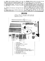
Fig. 2
1 Guide Rai Is
2 Extension Wings
3 See- Thru B lade Guard and Spl itter
4 Miter Gage
5 Be It and Pu Iley Guard
7 Rip Fence
8 V-Be It
9 Motor pulley
10 Hardware for Extension Wings
11 Blade Guard and Splitter Mounting Hardware
12 Tilting and Raising Lock Knobs, Switch Bracket,
Motor Mounting Hardware, Guide Rail Hardware
13 Motor Mounting Plate
14 Motor Mounting Plate Bracket
15 Arbor Wrench
16 Raising and Tilting Handwheels
J
Carefully unpack the saw and all loose items from
the carton. Fig. 2, illustrates all the loose items
packed with your saw.

~
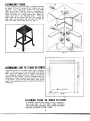
ASSEMBLING STAND
Fig- 4
Fig. 3
ASSEMBLING SAW TO STAND OR BENCH
~
:1
""
I'"
-1'1
~
:>
r- 16 DIA. (4) HOLES
-¥
"' ., $--
FRul~ I
fIg ~
FASTENING STAND OR BENCH TO FLOOR
" ~ "
If you purchased the 50-315 Stand, assemble the stand
as shown in Fig. 3, using the 24 screws and nuts
supplied. Only tighten the screws and nuts finger
tight at ~h.is time. NOTE: Fig. 4, illustrates the
proper relationship of the screws and nuts to the stand.
Place the stand on a level surface and tighten the
screws and nuts in the following order. First the
eight lower tie bar screws and nuts (A), second the
eight upper tie bar screws and nuts (8), and th ird the
eight top shelf screws and nuts (C) Fig. 4.
Assemble the saw to the 50-315 ~teel ~tana. IMPUK 1-
ANT: If the saw is to be used without the 50-315
Steel Stand, we suggest that it always be fastened
to a supporting surface using the holes on the bottom
ledge of the saw cabinet. Fig. 5, illustrates the size
and center to center distance of the holes to be drilled
in the bench. Care must be taken that a hole is pro-
vided in the supporting surface to facilitate the removal
of saw dus t.
I~ DUKINl.J Ut't:KA IIUN I Ht:Kt: I~ ANT I t:NUt:Nl. T
FOR THE TOOL TO TIP OVER, SLIDE OR WALK
ON SUPPORTING SURFACE, THE STAND OR BENCH
MUST BE SECURED TO THE FI._OOR.
4

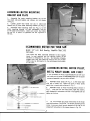
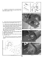
ASSEMBLING MOTOR MOUNTING
BRACKET AND PLATE
1. Assemble the motor mounting bracket (A) to the
two posts (8) and tighten set screws (C), as shown
in Fig. 6.
2.
Loosen screw that holds rod (0) in place and
remove rod (0) from motor mounting bracket (A) Fig. 6.
3.
Assemble motor mounting plate (E) Fig. 6. to the
motor mounting bracket (A) and reassemble rod (0)
to the plate and bracket. Make sure screw that holds
the rod (0) in place is tightened into the V-groove in
the rod.
RECOMMENDED MOTOR FOR YOUR SAW
~L.- " ...
This motor has been specially selected to best supply
power to your machine and the relative safety of the
machine is enhanced by its use. We therefore strongly
suggest that only this motor be used as the use of other
motors may be detrimental to the performance and safety
of the saw.
ASSEMBLING MOTOR, MOTOR PULLEY,
BELT & PULLEY GUARD, AND V-BELT
It you purchased the motor recommended for use with your
saw, make sure the motor is DISCONNECTED from the power
source and assemble it to your saw as follows:
1. Assemble motor pulley (A) Fig. 7, to the motor shaft
with hub of pulley out. Tighten set screw in motor pulley
against key in motor shaft, as shown in Fig. 7.
fig. 7
2. Assemble motor to motor mounting plate, as shown in
Fig. 7, using the four hex head screws, eight flat washers,
eight shakeproof lockwashers and four nuts suppl ied. Do not
tighten at this time.
J. t-lg.7A illustrates the proper relationship of the motor
mounting hardware. CAUTION: The proper grounding of the
motor, to prevent shock hazard, depends on the use of the
shakeproof lockwashers in the manner shown in Fig.7A.
5
rIg. I A
I fie molor recommenaea TOr use With your saw is the
62-042 11/2" H.P. Ball Bearing, Capacitor Start, 115
Volt motor.

4. Assemble the carriage bolt (A) to the belt ~nd pulley
guard bracket, using the 11/32" flat washer (8) and Tinner-
man nut (C), as shown in Fig.8.
Fig. 8
5. Slide the belt and pulley guard bracket (A) between the
motor plate and motor mounting plate, as shown in Fig. 9.
6. Position the belt and pulley guard bracket (A) so that
the motor pulley (8) is centered and through the hole In the
belt and pulley guard bracket, as shown in Fig. 10. Tighten
motor mounting screws, washers, lockwashers and nuts.
7. Using a straight edge, align the motor pulley to the arbor
pulley. If necessary move motor pulley in or out on motor
shaft. NOTE: Be sure guard bracket is still centered and
aligned with pulley as shown in Fig. 10.
Fig. 9
8. Assemble V-belt to the motor pulley and arbor pulley
and adjust for correct belt tension.
9. Place washer (C), spacer (0) and washer (E) on carriage
bolt, as shown in Fig. 11.
10. Assemble the belt and pulley cover (A) to the bracket
and fasten in place using the wing nut (B), as shown in Fig.11
and 12.
Fig. 10
Fig. 12
r-ig. II
6-

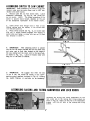
ASSEMBLING SWITCH TO SAW CABINET
-
1. Remove outer hex nut from switch stem. Leave
shakeproof lockwasher (A) Fig. 13, and inside hex
nut on switch. NOTE: The proper grounding of the
switch to prevent shock hazard, depends on the use
of the shakeproof lockwasher in the manner shown.
Fig. 13
2. Insert switch stem through hole in front of saw
cabinet making sure the keyway in the switch stem
is in the down position.
3. Place switch bracket (8) Fig. 14, on switch stem
with key in switch bracket engaged with keyway in
switch stem and fasten in place with hex nut (C) that
was removed in STEP 1.
Fig. 14
lD'\1
MOTOR~
POWER \ \~~~~
\
4. IMPORTANT: After attaching switch to cabinet
use the two tie straps provided and tie the power cord
and motor cord to front hole located On the ledge of
the saw cabinet and the motor cord to the back hole,
as shown In Fig. 14A. Leave all excess motor cord
hang out of the back of cabinet.
Fig. 1~ A
5. IMPORTANT: We suggest that when the saw
is not in use, the switch be locked in the "OFF"
position using a padlock, as shown in Fig. 15. Catalog
NO. 49-031 Padlock is available as an accessory.
Fig. 15
ASSEMBLING RAISING AND TILTING HANDWHEELS AND LOCK KNOBS
Assemble the raising and tilting handwheels (A) and
lock knobs (8) to the raising and tilting screws, as
shown in Fig. 16. Make sure the slot in the handwheels
engage with the roll pins in the raising and ti Iting
screws.
to og. 10
'I
IMPORTANT: When assembling the switch to the saw
cabinet, make sure the motor power cord is NOT con-
nected to the power source.

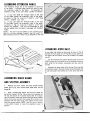
ASSEMBLING EXTENSION WINGS
The extension wings are to be fastened to each end
of the table. A straight edge should be used to level
the extension wings to the table. To assemble the
extension wings to the saw table, proceed as follows:
1. If your saw table has through holes on the side
of the table, attach the extension wing to the table,
as shown in Fig. 17. using the 7/16-20 x 1-1/2" long
screws, washers and nuts.
2. If your saw table has thrpaded holes on the side
of the table, attach the extension wing to thE: table,
as shown in Fig. 17, using the 7/16-20 x 1-1/2" long
screws and washers. The nuts are discarded as they
are not needed when the table is equipped with threaded
holes.
NOTE: The saw must be bolted to the supporting sur-
face or a sturdy ontrigger support must be used if a
table extension over 24 inches long is attached to the saw.
Fig. 17
ASSEMBLING GUIDE RAILS
tlg. I a
ASSEMBLING BLADE GUARD
AND SPLITTER ASSEMBLY
1. Remove cap screw. washer and outer spl itter bracket
holder (A) Fig. 19. Also remove blade, blade arbor nut and
flange (8).
2. Hold a straight edge against the saw arbor flange (C)
and splitter bracket (0) Fig. 19. and check for alignment on
the top and bottom of the splitter bracket (0). If an adjust-
ment is necessary loosen two screws that hold spl itter bracket
(0) to the trunnion and shift the bracket (0) to bring it into
alignment with saw arbor flange. Then tighten the two screws
that hold splitter bracket. NOTE: Snap out the nut retainer
in the splitter bracket to make this adjustment easier to
perform.
Fig. 19
8
1. The guide rail with the calibrations goes on the front of
the saw table and should be positioned as shown in Fig. 18.
Assemble the front guide rail (F) Fig.18to the saw table using
two spacers (B) and special screws (A) threaded into tapped
holes (C).
2. Use the remaining two spacers (B) and special screws (A)
Fig.18t to attach the front guide rail to the extension wings and
fasten using the flat washers, lockwashers and hex nuts (0)
provided.
3. Assemble the plain guide rail to the rear of the saw table
and extension wings in the same manner as the front guide rail.
Be sure both guide rails extend out to the same side of the
saw.

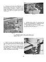
3. Thread nut (A) Fig. 20, onto threaded end of rod
(8) and thread rod (8) into the hole provided in the
trunnion bracket (C) as shown. If necessary a rod or
pin can be placed into hole (0) to assist in providing
leverage when threading the rod (8) into the trunnion
bracket. Then tighten nut (A) against trunnion bracket
(C), as shown.
Fig. 20
4. Assemble bracket (A) Fig. 21, to bracket (8) using
the screw, nut and lockwasher (C). Assemble the screw,
nut and lockwasher (0) to bracket iA) as shown.
5. Place bracket (8) Fig. 21, on rod (E) as shown,
and fasten using the screw and nut (F).
Fig. 21
6. Assemble the center portion of the splitter to the
splitter bracket (0), Fig. 19, and replace splitter bracket
holder (A) Fig. 19.
7. Remove nut, screw and lockwasher (8) Fig. 22,
from the rear splitter bracket and assemble the splitter
(A) to the bracket using the screw, nut and lockwasher
(8).
8. Replace saw blade and using a straight edge make
sure the splitter (A) Fig.22, is in alignment with the
saw blade, as shown. If necessary, the rear mounting
bracket assembly (C) can be adjusted to bring the
splitter into alignment with the saw blade.
Fig. 22
9

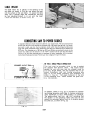
TABLE INSERT
Fig. 23
CONNECTING SAW TO POWER SOURCE
A separate electrical circuit should be used for your power tools. This circuit should not
be less than #12 wire and should be protected with a 20 Amp time lag fuse. If an exten-
sion cord is used, use only 3-wire extension cords which have 3-prong grounding type
plugs and 3-pole receptacles which accept the tools plug. For distances up to 100 feet use
#12 wire. For distances up to 150 feet use #10 wire. Before connecting the motor to the
pqwer line, make sure the switch is in the "OFF" position and be sure that the electric
current is of the same characteristics as stamped on motor nameplate. All line connec-
tions should make good contact. Running on low voltage will injure the motor.
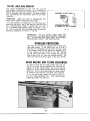
US VOLT, SINGLE PHASE OPERATION
This tool must be grounded while in use to protect
the operator from electric shock. The motors recom-
mended for use with your saw are shi pped wired for
115 Volt, Single Phase, and are equipped with an ap-
proved 3-conductor cord and 3-prong grounding type
plug to fit the proper grounding type receptacle, as
shovJn in Fig. 24. The green conductor in the cord
is the grounding wire. Never connect the green wire
to a live terminal.
fig. Z.
An adapter, shown in Fig. 25, is avai lable for connect-
ing 3-prong grounding type plugs to 2-prong receptacles.
THIS ADAPTER IS NOT APPLICABLE IN CANADA.
The green-colored rigid ear, lug, etc., extending from
the adapter is the grounding means and must be con-
nected to a pertnanent ground such as to properly ground-
ed outlet box, as shown in Fig. 25.
Fig. 25
10
The table insert (A) is placed in the opening in the
saw table, as shown in Fig. 23, and should be level
with the surface of the saw table. To adjust the table
insert use a straight edge and screwdriver and turn
the four adjusting screws in or out until the insert
is flush with the table, as shown in Fig. 23.

230 VOLT, SINGLE PHASE OPERATION
The motors recommended for use with your saw are
dual voltage, 115/230 Volt motors. If it is des ired to
operate your saw at 230 Volt, Single Phase, it is neces-
sary to reconnect the motor leads in the motor junction
box, by following the instructions given on the motor
nameplate.
IMPORTANT: Make sure motor is disconnected from
power source before reconnecting motor leads.
It is also necessary to replace the 115 Volt plug, sup-
plied with the motor, with a 230 Volt plug that has two
flat, current-carrying prongs in tandem, and one round
or "U"-shaped longer ground prong, as shown in Fig.
26. This is used only with the proper mating 3-conductor
grounding receptacle, as shown in Fig. 26.
Fig. 26
IMPORTANT: IN ALL CASES. MAKE SURE THE
RECE PTACLE IN QUESTION IS PROPERLY GROUND-
ED. IF YOU ARE NOT SURE HAVE A CERTIF lED
ELECTRICIAN CHECK THE RECEPTACLE.
OVERLOAD PROTECTION
BLADE RAISING AND TILTING MECHANISM
.
To tilt the saw blade, loosen lock knob (C) Fig. 27,
and turn tilting handwheel (0). When desired angle
is obtained, tighten lock knob (C).
Fit. 27
11
The motor on your saw is equipped with a reset over-
load relay button. If the motor shuts off or fai Is to
start due to overloading (cutting stock too fast, using
a dull blade, using the saw beyond its capacity, etc.)
or low voltage turn the switch to the "off" positiOn,
let the motor cool three to five minutes and push the
reset button which wi II reset the overload device. The
motor can then be turned on again in the usual manner.
To raise or lower the saw blade.. loosen lock knob (A)
Fig. 27, and turn raising handwheel (B). With the ex-
ception of hollow ground blades, the blade should be
raised 1/8" to 1/4" above the top surface a the material
being cut. With hollow ground blades the blade should
be raised to the maximum to provide chip clearance.

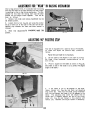
ADJUSTMENT FOR ttWEAR" IN RAISING MECHANISM
After'a long period of time, it is possible that the raising
worm and the teeth on the arbor bracket wi II wear s I ight-
Iy resulting in play in the raising mechanism. To com-
pensate for this wear the raising worm and the arbor
bracket can be brought closer together. This can be
done as follows:
1. Remove lock knob and raising handwheel but do
not remove poi nter.
2. Loosen lock nut (A) Fig. 28, and using the pointer
(B) as a lever turn to the right or left until all the per-
ceptible play between the worm and arbor bracket is
removed.
is
completed,
reset the
3.
When this adjustment
pointer.
Fig. 28
ADJUSTING 900 POSITIVE STOP
Your saw is equipped with a positive stop at 90 degrees.
To check and adjust the positive stop, proceed as
follows:
Raise the saw blade to its maximum.
2.
Set the blade at 90 degrees to the table by turning
the blade tilting handwheel counterc1ockwise as far
as it will go.
3. Place a square on the table as shown in Fig. 29.
and che~k to see if the blade is at a perfect 90 degree
angle to the table..
Fig. 29
4. If the blade is not at 90 degrees to the table,
loosen locknut (A) Fig. 30, and back out adjusting
stop screw (B). Then turn the blade ti Iting handwheel
unti I you are certain the blade is at 90 degrees to the
table. The adjusting stop screw (B) should then be
turned unti I it bottoms against the end of the ti Iting
screw (C) Fig. 30, and locked in this position with
locknut (A). Recheck and adjust further if necessary.
Fig. 30
12

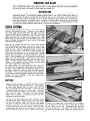
RIP FENCE OPERATION AND ADJUSTMENTS
To move the rip fence, raise the c lamp lever (A) Fig.31,
as far as it will go and move the fence to the desired
position on the table. For fine movement of the rip
fence, raise the clamp lever (A) Fig. 31, as far as it
will go and push in and turn the "micro-set" knob (8).
When the clamp lever (A) Fig. 31, is all the way down,
clamping action on the front and rear guide rails should
be equal. If clamping action on the rear guide rai I
is more or less than clamping action of front guide
rail, an adjustment of the rear clamp hook is made
by turning screw (C) Fig. 31. Turning the screw (C)
clockwise will increase tension and turning it counter-
clockwise will decrease tension. When lowering clamp
lever (A) slowly, you will notice clamp action on front
guide rai I first and as lever is moved downward to
its lowest pos ition, clamp action wi II take place on
rear guide rai I.
Your machine is shipped from the factory with the table
adjusted so the miter gage slots are parallel to the
saw blade. The fence, therefore, should be adjusted
so it is parallel to the miter gage slots. To check the
ri p fence, set it at one of the m iter gage s lots and
tighten the clamp lever (A) Fig. 31. If an adjustment
is necessary, loosen the two front cap screws (0)
Fig. 31 and raise the clamp lever (A). Move the rear
end of the fence body to one s ide or the other unti I it
is parallel with the miter gage slot. Then lock the
clamp lever (A), by pushing it down, and tighten the
two clamp screws (0).
Fig.31
MITER GAGE
OPERATION AND ADJUSTMENTS
Your Rockwe II Miter Gage is accurate Iy constructed and
equipped with individually adjustable index stops at
90 degrees and 45 degrees right and left. Adjustment
to the index stops can be made by tightening or loosening
the three adjusting screws (A) Fig. 32.
Fig. 32
To operate the miter gage, simply loosen the lock knob
(8) Fig. 32, and move the pody of the miter gage (C) to
the desired angle. The miter gage bcxly wi II stop at
0 degrees and 45 degrees both right and left. To rotate
the miter gage body past these points, the stop link
(0) Fig. 32, must be flipped out of the way.
To check and adjust the 90 degree setting ct the miter
gage, set the gage at 90 degrees, as shown in Fig. 33.
Place a square against the face of the miter gage and
along one of the miter gage slots, as shown. If the
gage is not at 90 degrees, loosen the locking knob (A)
and move the miter gage body until you are certain the
gage is set at 90 degrees. Then adjust the stop screw
(8) so it strikes the stop link when the gage is at 90
degrees, and tighten nut (C).
1.3
Fig. 33
The ri p fence can be used on either s ide of the saw
blade. The most common location is on the right hand
s ide. The ri p fence is gu ided by means of gu ide rai Is
fastened to the front and rear of the table. The front
guide rai I is cal ibrated to show the distance the fence
is set from the saw blade.

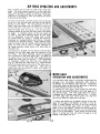
REMOVING SAW BLADE
OPERA TION
CROSS CUTTING
Cross cutting requires the use of the miter gage to
position and guide the work. Place the v.ork against
the miter gage and advance both the gage and work
toward the saw blade, as shown in Fig. 34. The miter
gage may be used in either table slot, however, most
operators prefer the left groove for average work. When
bevel cutting (blade ti Ited), use the table groove that
does not cause interference of your hand or miter gage
with the saw blade guard.
Start the cut slowly and hold the work firmly against
the miter gage and the table. One of the rules in run-
ning a saw is that you never hang onto or touch a free
piece of work. Hold the supported piece, not the free
piece that is cut off. The feed in cross cutting con-
tinues until the work is cut in two, then the miter gage
and. work are pulled back to the starting point. Before
pulling the work back, it is good practice to give the
work a little sideways shift to move the work slightly
away from the saw blade. Never pick up any short
length of free work from the table whi Ie the saw is run-
ning. A smart operator never touches a cut-off piece
unless it is at least a foot long. Never use the fence
as a cut-off gage when cross cutting.
For added safety and convenience the miter gage can
be fitted with an auxiliary wood-facing that should be
at least 1 inch higher than the maximum depth of cut,
and should extend 12 inches or more on either side of
the blade. This auxiliary wood-facing can be fastened
to the front of the miter gage by using two wood screws
through the holes rxovided in the miter -gage body
and into the wood-facing.
Fig. 35
RIPPING
Fig. 36
the work will either stay on the table, tilt up slightly
and be caught by the rear end of the guard or slide
off the table to the floor. Alternately, the feed can
continue to the end of the table, after which the work
is lifted and brought back along the outside edge of
14
When removing saw blades from your saw, make sure the saw is disconnected from the power
source. Remove the table insert, place a block of wood against the front of the saw blade and
and using the arbor nut wrench, turn the arbor nut toward you.
Plain sawing includes ripping and cross cutting, plus a few other standard operations of a
fundamental nature. The following methods feature safety. As with all power tools there is a
certain amount of hazard invloved with the operator and his use of the tool. Using the tool with
the respect and caution demanded as far as safety precautions are concerRed will considerably
lessen the possibility of personal injury. However, if normal safety precautions are overlooked
or completely ignored, personal injury to the operator can develop. It is good practice to make
trial cuts using scrap material when setting up your saw for operation.
Ripping is the operation of making a lengthwise cut
through a board, as shown in Fig. 35, and the rip fence
IS used to position and guide the work. One edge of
the work rides against the rip fence while the flat
side of the board rest on the table. Since the work
is pushed along the fence, it must have a straight
edge and make solid contact with the table. The saw
guard must be used. The guard has anti-kickback
fingers and a splitter to prevent the saw kerf from
closing and binding the blade.
Start the motor and advance the work holding it down
and against the fence. Never stand in the line of the
saw cut when ripping. Hold the work with both hands
and push it along the fence and into the saw blade
as shown in Fig. 35. The work can then be fed through
the saw blade with one or two hands. After the work
is beyond the saw blade and anti-kickback fingers the
hand is removed from the work. When this is done

the fence. The waste stock remains on the table and
is not touched with the hands until the saw is stopped
unless it is a large piece allowing safe removal.
If the ripped work is less than 3 inches wide, a push
stick should be used to complete the feed, as shown
in Fig. 36. The push stick can easily be made from
scrap [llaterial. When ripping 2 inches or narrower,
make an auxiliary guide and fasten it to the rip fence,
and use a push stick.
A
When cutting thin material (such as veneer), the material may
slide or catch between the bottom of the rip fence and the
table surface, causing loss of control of the work piece.
~"~
To prevent this from happening, a wood facing should be at-
tached to the fence as follows:
"'"
./
'-
~
.,...
"
1. Cut a piece of wood approximately 3f4" thick to the
length and height of the rip fence.
~.
2. Attach wood fal:lng (A) Fig. 37 to the rip fence (B)
using four wood screws (C) inserted through the holes pro-
vided as shown in Fig. 37.
.~
3. Care should be taken that the wood facing' fits flush to
the table surface along edge (0), Fig. 37. so that thin work
material cannot slide under.
Fig. 37
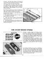
USING ACCESSORY MOULDING CUTTERHEAD
rl.4oulding is cutting a shape on the edge or face of
the work. Cutting mouldings with a moulding cutter-
head in the circular saw is a fast, safe and clean opera-
tion. The many different knife shapes available make
it possible for the operator to produce almost any kind
of mouldings, such as various styles of corner moulds,
picture frames, table edges, etc.
The moulding head consists of a cutterhead in which
can be mounted various shapes of steel knives, as shown
in Fig. 38. Each of the three knives in a set is fitted
into a groove in the cutterhead and securely clamped
with a screw. The knife grooves should be kept free
of sawdust which would prevent the cutter from seating
properly.
Fig. 38
The moulding cutterhead (A) Fig. 39, is assembled to
the saw arbor in the same manner as the saw blade.
The guard, splitter and anti-kickback finger assembly
can not be used when moulding and must be removed
from the saw as shown. Also, the accessory moulding
cutterhead table insert (B) Fig. 39, must be used in
place of the standard table insert.
Fig. 39
15

It is necessary when using the moulding cutterhead
to add wood-facing to one a both sides of the rip fence
as shown in Fig. 40. The wood-facing is attached to
the fence with wood screws through the holes provided
in the fence. 3/4 inch stock is suitable for most work
although an occasional job may require 1 inch facing.
Position the wood-facing over the cutterhead with the
cutterhead below the surface of the table. Turn the
saw on and rai se the cutterhead. The cutterhead wi II
cut its ONn groove in the wood-facing. Fig. 40 shows
a typical moulding operation. NEVER USE MOULDING
CUTTERHEAD IN A BEVEL POSITION.
IMPORTANT: NEVER RUN THE STOCK BETWEEN
THE FENCE AND THE MOULDING CUTTERHEAD
AS IRREGULAR SHAPED WOOD WI LL CAUSE KICK-
BACK.
When moulding end grain, the miter gage is used. The
feed should be slowed up at the end of the cut to pre-
vent spl i nteri ng.
In all cuts, attention should be given the grain, making
the cut in the same direction as the grain whenever
possible.
ALWAYS INSTALL BLADE GUARD AFTER OPERA-
TION IS COMPLETE.
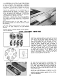
DADO HEAD
ACCESSORY
USING
Dadoing is cutting a rabbet or a wide groove into the
work. Most dado head sets are made up of two outside
saws and four or five inside cutters, as shown in Fig.
41. Various combi nati ons of saws and cutters are
used to cut grooves from 1/8" to 13/16" fa- use in
shelving, making joints, tenoning, grooving, etc. The
cutters are heavily swaged and must be arranged so
that this heavy portion falls in the gullets of the out-
side saws, as shown in Fig. 42. The saw and cutter
overlap is shown in Fig. 43, (A) being the outside
saw, (8) and inside cutter, and (C) a I:8per washer
or washers which can be used as needed to control
the exact width of groove. A 1/4" groove is cut by
using the two outside saws. The teeth of the saws
should be positioned so that the raker on one saw is
beside the cutting teeth on the other saw.
Fig. 43
The dado head set (A) Fig. 44, is assembled to the
saw arbor in the same manner as the saw blade. The
guard, splitter and anti-kickback finger assembly can
not be used when dadoing and must be removed from
the saw, as shown. AlSO, the accessory dado head
table insert (8) Fig. 44, must be used in place of the
standard table insert.
NEVER USE THE DADO HEAD IN A BEVEL POSITION.
ALWAYS INSTALL BLADE GUARD AFTER OPERA-
T10N IS COMPLETE.
16

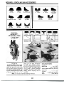
ROCKWEll CIRCULAR SAW ACCESSORIES
DADO HEAD SETS
Sets are made of high qualit
carefully hardened and te
Blades and chippers
assure clean, even Cui
the grain.
With a Moulding Cutterhead and these
32 Sets of Knives You Can Cut Thou-
sands of Different Mouldings On Your
Circular Saw.
Each SRt {;onsists of three knives.1A lb.
Knives are shown ~'f! size.
mpered..
matched to
ith or acros~
No. 34-172 (old 1172) Tenoning Attach-
ment. Simplifies operation of cutting
tenons for mortise and tenon joints.
Stock can be fed with one hand-far
removed from saw blade(s). Handles
stock up to 2%" thick. Base plate in-
cluded. 30 lbs.
No. 34-171 (old 1171) Spacer Collars.
Set of two: lA" and %" widths with %"
arbor hole. For spacing saw blades to
cut tenons in one pass. lIb.
MOULDING CUTTERHEAD SETS
No. 34.333 Production Type Dado Head
Set. Consisting of two hollow-
ground outer blades (6" dia. x Ys"
th~ck) and four inside cutters (one 1/1"
thick; two ~~., thick; one ~1Ii" thick).
With ~~" arbor hole. Cuts grooves
from ~:.." to 1:\11;" wide. 31/l lbs.
No. 33.212 Production Type Dado
Head Set. Consisting of two hollow
ground outer blades (8" diameter by
~~" thick) and four inside cutters
(one ;~" thick; two ;~" thick; one ~16"
thick). With %" arbor hole. Cuts
grooves from ~ix" to 1:}11;" wide. 8 lbs.
No. 34-334 Economy Dado Head Set.
Consisting of two flat-ground outer
blades (6" dia. x ]/~" thick) and five in-
side cutters (four ;ix" thick; one 1/16"
thick). With 1A" arbor hole. Cuts
grooves from ~\." to 1=)116" wide. 4 lbs.
_u.c~ld~
~
.[
~~~.,~
'"'
~
No. 34-568 (old 865) Clamp Attach-
ment for Miter Gage. Holds work se.
curely for accurate miter and cut-off
operati{)ns. Complete with clamp bar,
front and rear posts and two sliding
clamp screws and blocks. For use with
No. 34-895 Miter Gage. 11/2 lbs.
No. 34.873 (old 873) Extra Clamp
Screw and Block Only. For use with No.
34-568 clamp attachment. % lb.
No. 43-170 (Old 1170) Tenoner for use
with No. 43-186 (old 1186) Sliding Jig.
Can also be used on wood shaper. 21
lbs.
No. 34-813 Heavy Duty Moulding Cut-
terhead & Knife Set. Includes No. 34-
562 (old 265) cutterhead, No. 34-521
(old 1521) wrench and Nos. 35-102, 35-103,35-221
and 35-222 cutterhead knives.
For use on lh" and .%" dia. arbors. 4 lbs.
No. 34-821 Basic Moulding Cutterhead
& Knife Set. Includes No. 34-562 (old
265) cutterhead. No. 34-521 (old 1521)
wrench and No. 35-102 set of knives.
For use on lh" and %" dia. arbors. 3 lbs.
No. 34-562 (old 265) Moulding Cutter-
head. Heavy Duty, Solid-Steel Type.
For use on lh" and 'Ys" arbors. Less
wrench and knives. 3 lbs.
No. 34-521 (old 1521) Wrench. For
moulding cutterhead. Ys lb.
17

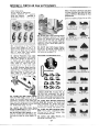
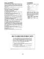
ROCKWEll CIRCULAR SAW ACCESSORIES
35-221
Thumb Moulding
35-204
3/4" Flute
35-211
1" Flute
35-241
1/4" Tongue
35-242
lf4" Groove
35-243
Cove & Bead
Moulding
35-247
Door Lip
35-245
Oval Sash
35-222
Ih" Cove & 1/4 ff Flute
35-223
Ogee
35-224
0/8" Cove
35-236
%" Flute
35-237
5fa" Bead
35-238
3/4" Bead
Make These Cuts and Joints and Many More
With Your Rockwell Micro-SetTM Adjustable Dado
SPECI FICA TIONS
Catalog No. 34-959
Width of Cut. 1,4 II to 1*6"
(6.35 to 20.64 mm)
Maximum Depth of Cut 3f4 " (19.05 mm)
No. of Teeth 8
Fits Arbor. ., " Speed.. .
Weight. ..
Easy to use!
Just dial the width of cut you want
and get perfect results every time!
Here's the dado that stays on the
saw! No need to remove it from the
saw arbor to change settings. Just
turn the calibrated dial to the width
of cut you want from 1/4" to 1:t16"
NOTE: Do not use on macl
~"115.1j7mmJ
Not to Exceed 7000 RPM
21bs.(.907kg)
18
wide. up to 3/4" deep. The Micro-
Set dado also ploughs, rabbets,
grooves and makes decorative cuts.
The 63/8" blade is carbide tipped
to cut wood or plastic laminates
smoothly and truly, more times.
Sturdy plastic carrying case is
included.hines
exceeding 7000 rpm.

ACCESSORIES
Saw Blades (with o/s" arbor hole. Each
1;2 lbs.)
BASIC ACCESSORIES
No. 62-042 Motor, 11/2 HP, Single Phase, Ball Bearing, Capa-
citor Start, 3450 RPM, 115/230 V, TEFC, with 8-foot Cord
with 115V Grounding Type Plug, Remote Control On-Off
Toggle Switch with Locking Feature and Cord Connected to
Motor. 42 lbs.
No. 34-965 Belt and Pulley Guard. Use with 62-042 Motor.
3lbs.
No. 50-315 Stand for 10" Contractors' Saw. 28 lbs.
ADDITIONAL ROCKWELL ACCESSORIES
For Saw Blades, See Section G2, Page 4.
No. 34-154 Standard Table Insert. 134 lbs.
No. 34-254 Dado Head Table Insert (for 6" diameter dado
heads only). 11/2 lbs.
No. 34-453 Moulding Cutterhead Table Insert. 11/2 lbs.
No. 34-472 Extra Long Guide Bars that permit ripping to the
center of a 100" panel. 22 lbs.
No. 34-550 Metric Extra Long Guide Bars. same length as
34-472 but with metric calibrations in centimeters and milli-
meters. 22 lbs.
No. 34-551 Metric Extra Long Front Guide Bar only. Calibrated
in centimeters and millimeters.lllbs.
No. 34-552 Metric Front Guide Bar. Same length as Standard
Equipment but with calibrations in centimeters and milli-
meters. 7 lbs.
No. 34-658 "See- Thru" Splitter-Mounted Blade Guard com-
plete with spring-loaded anti-kickback fingers. 6 lbs.
No. 34-895 Auto-Set.a> Miter Gage. For straight and angle
operations. Has 3/8" x 3/4" X 18/' guide bar and pivoting work
support body with pointer and calibrations reading through
1200 swing. Adjustable, positive stops at 900 and 450 posi-
tions. Accommodates No. 34-568 (old 865) Clamp Attach-
ment. 3'/2 lbs.
No. 34-568 Clamp Attachment for Miter Gage. 11/2 lbs.
No. 41-043 Motor Pulley, %" bore, 3" diameter, for 345o.RPM
motors. 2 lbs.
No. 49-034 V-belt, 44" O.C. 1/2 lb.
No. 49-364 Retractable Caster Set. Fits 50-315 Stand. 13 lbs.
19
Carbide-Tipped Combination. Recom-
mended for general purpose use on
hard or soft woods, certain plastics,
laminates. Each tooth has an alternate
top bevel grind (ATB). Entire blade is
hard chrome finished.

-;; Mem~~,~~8118
-f~4290 Ra" R:()8d
, ~,
--"P~;_(9Q_f) ~6-1700
-~- ~I --'*i~ ~:;;:~~:~:'f.(~
Van Nuys, CA~14Q6 'f
16259 Stagg'Str.t f--{
Phone: (213) 9~-1242
'\\
*\\\~-
--, ;,
TEXAS (contInued)
Houslon 77092-Poner-Ceble Corpora"on
5201 MoIc,,"IIda'e, Suole B-9
Lubbock 7940S-Lubbock Eleclnc Co Inc
110834IhSlree'
Odessa 79763-W & W Tool Repa" Shop
614 50Ulh Granl
San AnlOnlO 78218-Por1erCable Co.po,a"on
2800NELoop410
UTAH
Sail Lake c,ty 8411S-Porter-Cable Corpo'a"on
29905 W Temple
VIRGINIA
Nor1olk 23517-B,.on Eleclr,c Company Inc
424 Wesl251h 51'ee'
R,chmond 2322(}-Pofter-Cable Corpora"on
1 705 Dabney Road
Roanoke 240 13-Roanoke Armalure Co
1108';, 51reel 5E
WASHINGTON
Kennew,ck 9933&- Tool Repa" Company
419AWeslEn"al
5ean'e 98101-PofterCable Co.po,a"on
1918 M,no, Ayenue
Spokane 99202-5pokane Powe' Tool
E 801 T,enl Ayenue
Yak,ma 9890 1--{;oop8' Elec Mlr 5e",ce
2055 41h Ayenue
WEST VIRGINIA
Hun"nglon 2570 I-Lawler Elec'r,c Molo. Co
202 Adams Ayenue
Wheelong 26003-Kennedy Hdwe
3300 McCulloch Slreel
WISCONSIN
M"waukoe 53222-Por1erCable Co,po,a"on
10700 W Bu"O'9h SIres'
WYOMING
Casper 82601-c.- Saw Shop 1475 McK,nley
PUERTO RICO
5,o"a Bayamon 00619-B&M Eleclr,c Tool
Ropa" Con's, Callo 49 Bloquo51
Casa 27 Ayonue Wesl Ma,n
~
ALBERTA
Calgo'Y Alberto T2G 489
4411 Mon,tobo ROOd 5E
Phone 140312870462
Edmonlon T5P 3X6
106321691h51'001
Phone 140314895587
BRITISH COLUMBIA
Voncou.e' 8 C V5Y IL4
45 We" 7th A.enue
Phone 1604) 879.6622
MANITOBA
W,nn,P09 Mon"obe R3H OH2
1699 Oub"n A.enue
Phone 12041633.9259
ONTARIO
M".,...uge Onto"o L4V IJ2
"63 Northom O".e
Phone 1416) 6775330
Guelph Onto'oo N1H 6M7
"4 'moe"o' Rood
Phone 15191836.4390
onawa Onte,oo K2A 3X2
851 R,chmond Rood
Phone 1613)7281124
Ouebec
5t Le",enl
(Mont'eell. PO H4N 1 W2
523 Rue De..o""",, St,eel
Phone 15141336.8772
Ste FoyOuebecG1N 4L5
Su"e 202
2202 Rue Le.oo..e,
Phone (418)6817305
INDIANA
Elkha" 465'S- Thunando, Co,po,a"on
1923 Ma'kle A.onuo
Go.hon 4652~&L Elecmc Molo, Ropa.
1405 C",cago A.enuo
Ind'anapol,. 46268-Po"ocCable Co,po,a"on
5317W86"'SI'ee'
IOWA
De. Mo,ne. 50309-Puckett Eleclr,c Tool. Inc
1011 KeoWa,
KANSAS
W,c",la 67213-R,c"mond Elec'roc Co
911 Maple
LOUISIANA
Kenne, 70062-Po"ecCable CCrpo'al,on
24400 Vele'an. Memoroal Hwy
MAINE
Po"'and 04104-M and W Eleclroc
38 Po"land S"ee'
MARVLAND
Ball,mo,e 21 20S-Po"ecCable Co'PO'a"on
47'4 E'dman A.enue
Hyall.."'e 2078'-PonecCable Co,po,a"on
48" Ken"wonh A.enue
MASSACHUSETTS
BO"on (AII.,oni 021 34-Po"ecCable CC,po.a"on
4 1 4 Cambr'dge SI'ee'
Spong',elO 01 1 os-Sew GenIe, 472 Mam S',ee'
MICHIGAN
G'and Rap'd' 49506-PonecCable Co,po,a"on
2750 B.c"c'e.' Do.e 5 E
Soulhl,eld (DeI'OolI4807S-PonerCable Co.po,a"on
1 8650 W 8 M"e Road PO Bo' 2065
MINNESOTA
Mmneapol,. 55429-Po"erCable Co,po,a"on
431568'" A.enue Non"
MISSISSIPPI
Jack.on 39204-Flann'gan Elec CC Inc
328 OakOale S'reel
MISSOURI
No"" Kan.a. C"y 64 I 1S-PonecCable CCrpo,a"on
,'41Swol,A.enuePO Bo,12)93
5' Lou'. 63139-PonecClble CCrpo,""on
2348 Hlmplon A.enue
MONTANA
B"'mg. 59101-Allen. Elecmc Tool Repa.
4315, Jo"n.
M"5OUII 598Q6-C,'Y Eleclroc
Elecllo Se""ce Cen'e, D,. '919 HI"'e
NEBRASKA
Omaha 68102- Tl1aCke, Elec",c Co
2209 Cum'ng S"eel
NEVADA
LI' Vega. 89109- Tool So"',ce Inc
3229 Indu"',al Road
Reno 89504-Landa Elec",c Co '40 Manuel S"eel
NEW HAMPSHIRE
Keene 03431-{;&R Elec M" Repa.
453 Wmcl1e.'e' S"ee'
NEWJERSEV
Je,..y C"y 07304-Rudoll Bas. Inc
45 Hilladay S"ee'
Un,on 07083--PonecCable CC'PO'I"on
945 Bill A.enue
NEW MEXICO
Albuque'que 871 08-J.M Tool Repa. CCmplny
116 Tennes... NE
Albuquerque 87107-Telco Eleclroc Inc
2906 Fou"" 51'.., NW
NEW YORK
Cl1eeklowagl , 422S-Ka"e Sew & Supply CC Inc
385 Nagel Dn.e
FluSl1mg , 136s-Poner.Cable Corpora"on
1 7525 Ho.lce Ha'd,ng Expwy
K'ngslon '2401-Fowle' & Keoll1 Supply CC
104 Smolh Avenue
Manl1anan 1001~...Cable Corpora'","
132 L"'"yette 51""
NEW YORK loo"tl"uodl
New Yo,k 10013-"u"01l Ba.. Inc
175 Lalayatte SI'eel
Roche,'er 1460~ackson Saw & "";Ie Co
517SIalaStreel
Roc"e,'er 14609-0 G Sc"warz
430 Atlanl,c Avenue
Soheno<:tady 12303-8a"ett Elo<: Sarv,ce Ino
112Hon~Street
Sy,aou.o 1 3224-Pono,.Cable Co,po,a"on
2740 Er,e Boulova'd E
vasta I 138SO-Casoade ElaClnc Inc
416 Com."..ce Road
NORTH CAROLINA
C"arlotte 28209-Pono,.Cablo Co'oora"on
4612 Soul" Boulova'd
H'g" Po,n! 27~AIM Tool. Inco'poralod
2708 "'vett Dnve
NORTH DAKOTA
"a'go 58107-Acme Elo<:tnc Moto- Bo,2048
OHIO
Boave,creek 45432-Aul"onzed Tool SaN'ce Co
3787 Daytonxen,a Road
C,nc,nnat, 45215-P'0Ie..,onal Tool So..,ce
10265 Spanan Dnve Bldg H
Columbu. 4321 S-Pone, Cable Corpo,a"on
4560 Ind,anola Avenue
Non" Canton 4472()-N CaMon Repa,' S"op
1106t"S"oetE
Toledo 43606-Powo' Tool Sale. & 59..,ce
2934 Dougla. Road
Young.,own 44512-Mott Maste' Powe' Tool.
5228 Ma'ket Street
OKLAHOMA
Okla"oma C"y 73107-Pone,Cable CO'pora"on
3631 N W 23'd St'oot
OREGON
Eugene 97402-J,m. Tool Sa..'oo
515 W".on St,ee'
Medlord 97501-"eo. Saw S"op
1838 Della Wale'. Roa"
_'and 97212-Poner.Cable CO'pora"on
51 N E Hanoock
PENNSYLVANIA
AlieMown 181 03-{;uno Electno Ropa,r
825 S 5t"
Bono"em 19020-Po,'e,.C",'e Co,po""on
E'p,e.oway 95 In"u.tn,1 Con'e'
3599 Me,"ow Lane,
P""adolp",a 1 91 06-Swanga' B,ot"or.
116Non"3r"S"ae'
RHODE ISLAND
P,ov",once 02914-Pono..Cable Co,po,a"on
1009 Wa,o,man Avenue
SOUTH CAROLINA
C"arle.ton 29407-Della Elo<:tnc Moto',
1906 Mee"ng S"oe'
Columb,a 29203-Mann E;oc"'o Ropa,' Co
3600 Ma,n S"eot
TENNESSEE
"no..,lIe 37917-S"op Equ'pmeM So.. Co
2706 Non" B,oadway
Memp"" 38116-PonorCabie Corpo,a"on
1 004 Ea.' B'ook. Road
Na."v"'e 37203-"&" Tool.
606 Demonbroun S"eet
TEXAS
Amarillo 79105-GE Jona. Eloctnc Co
204 Non" Polk S"eel
Corpu' C"ns" 78405-Otto Duko. Mac"'na~ Co.
2588 Morgan S"Mt
Dalla' 75247-Po"e..C""e Co,po,a"on
3160 Commonwo,"h Dn,e
5u"e 180 Commonwe,lIh Plaza
EI Paso 7995O-Fra- Wagnar Co.
1225 Toxa. Avonue
Fon WOr1h 76111-Modorn Tool Repal'
2704 E BoIknap
Haltom City 76117-C&DTool R_" SaN"o
2532 Carson Avenue
ALABAMA
B.m'nqham 35209-Pone,.Clble CO'oo'"I'on
131 a,moo' Roo" Su"e105
ALASKA
Ancho'"ge 99501-Ae'0 SeN,ces Co
201 PoSI RoaO
Fa.blnks 99706-F","'"nks Ae'o SeN,ces Inc
Bo' 60590
ARIZONA
Phcon" 85014-{;lenns Tool SIN,ce
4036 Nonh 1 31h WIY
Tucson 8571 9-Elecl"c Molo- Complny
10288,ooOWay
ARKANSAS
UIII. Rock 72202-Elocl"c Tool SeN,ce
1419WesI10IhSI,...,
CALIFORNIA
EI CI~n 92021-Besllmplcl SeN,ce
354 WIlle' WlY
Eu'eka 95501-Senn Elecl"c Co
1801 FI"',eIO SI,...'
F,esno 93703-R&R Mlch,ne'Y & Elecl'" Inc
1919 E Hom. A.enue
los Ang.'es 90007-Poll., Cable Co,po,""on
2400 S G,"n" A.lnue
"oOeslo 95351-S'"n,slaus Elec "" Wks
504 Awe' AD
o,ange 92668-Pone' Cable Co-oo,""on
385 Nonh Anahe,m Boule.a'O
Re""'nq 96001 -Eloc"'c ToollnO "°10..
2710 ReseN'" lIne
Sacramenlo 95S14-ConS"uc"on InOusl SeN Co
1211 C S"..I
San lean",o 94577-Pone' Cable Co-PO'a"on
3039 Teagl'- S"...,
SonIa CII,a 9505Q-Pone,CaOle Co'oo,."on
2305 De La C'uz Bou,".I'O
Sanll Rosa 95401 -Acme Eloc"'c Tool Rep.. 1
742 W"son S"...,
V.n Nuys 91406-Rockwelllnlema"onll Co,p
16259 Slagg S"...,
COLORADO
Den.e, 80207-Pon"CIOle CO'oo,""on
4900 E 391h A.enue
CONNECTICUT
""nChesle' Q604Q-Po"e,Clble Cooroo,."on
57 TollanO Tumpoke
New HI.en 06513-New H..en Elec ""ch Co
100 Fullon Te',"ce
FLORIOA
H,"leah 33014-Pone' Cable Co,oo,."on
16373 N W 571h A.enue
Jackson."," 3220~Pone,.CeOle CO'oo,a"on
51 7 Gessel A.enue
o,lan"o 32803-Pone'.Cable Co,oo,""on
1807 y, Wonle' PI,k Roa"
Pen..cola 32581-EIec"'c "" S.c Inc
3810 HOP'ons S"eel
Tlmpa 33609-Pone, Cable Co,oo,."on
4536 W Kennedy Boule..,O
GEORGIA
Fo'esl P.,k 3005Q-Po"e,.Cable Co'oo'a"on
4017 Jonesbo,o Road
Sa..nn.h 31402-Wh"e Hdwe
Cong,ess & Wh""ke,
HAWAII
H"o 9672Q-Hlwa" Plln'nq ""'lIO
380 K.noelehua A.enue
Honolulu 96819-Rockwell Intema"onal Co'p
3209 Koaplkl S"...,
Kahulu, 96732-au' Powe' Tool SeN.,e
251 H2llloS"...,
IDAHO
Boose 8370~A. EQu'pmenl Complny
2350 Soulh o,cha'd S"..I
Idaho FIlls 83401-Ross""s Eloc",c "oloor
1501 South Capo'" A.enue
l_slon 83501-WI'" Tool SeN,ce 513 Thlon
ILLINOIS
"e"058 PI'" (Ch""gol601~".cabIe
Co_"llon .533 Nonh Avenue
-
 1
1
-
 2
2
-
 3
3
-
 4
4
-
 5
5
-
 6
6
-
 7
7
-
 8
8
-
 9
9
-
 10
10
-
 11
11
-
 12
12
-
 13
13
-
 14
14
-
 15
15
-
 16
16
-
 17
17
-
 18
18
-
 19
19
-
 20
20


