Page is loading ...

Variable Area Flow Meter
EZ-View® Flow Meters and Flow-Alerts
VAM-UM-00367-EN-03 (October 2019)
User Manual
w ww . . co m
information@itm.com1.800.561.8187

CONTENTS
Introduction � � � � � � � � � � � � � � � � � � � � � � � � � � � � � � � � � � � � � � � � � � � � � � � � � � 5
Operating Principle � � � � � � � � � � � � � � � � � � � � � � � � � � � � � � � � � � � � � � � � � � � � � 7
Installation� � � � � � � � � � � � � � � � � � � � � � � � � � � � � � � � � � � � � � � � � � � � � � � � � � � � 8
Precautions � � � � � � � � � � � � � � � � � � � � � � � � � � � � � � � � � � � � � � � � � � 8
Piping Plumbing � � � � � � � � � � � � � � � � � � � � � � � � � � � � � � � � � � � � � � � 9
Flow Direction � � � � � � � � � � � � � � � � � � � � � � � � � � � � � � � � � � � � � � � � 9
Mounting Orientation� � � � � � � � � � � � � � � � � � � � � � � � � � � � � � � � � � � 10
Models with 1 in� (25�40 mm) Male NPTF End Connections � � � � � � � � � � � 10
Models with PVC Socket Weld End Fittings � � � � � � � � � � � � � � � � � � � � � 11
Models with Brass Sweat End Fittings� � � � � � � � � � � � � � � � � � � � � � � � � 12
Models with Male, Metal or PVC Threaded End Fittings� � � � � � � � � � � � � � 13
Models with Female, Metal Threaded End Fittings� � � � � � � � � � � � � � � � � 14
Flow-Alert Switch Options � � � � � � � � � � � � � � � � � � � � � � � � � � � � � � � � � � � � � � � 15
Flow-Alert Latching Limit Switch� � � � � � � � � � � � � � � � � � � � � � � � � � � � 15
Flow-Alert Reed Limit Switch � � � � � � � � � � � � � � � � � � � � � � � � � � � � � � 16
Flow-Alert Switch Installation � � � � � � � � � � � � � � � � � � � � � � � � � � � � � � � � � � � � � 17
Latching Switch� � � � � � � � � � � � � � � � � � � � � � � � � � � � � � � � � � � � � � � 17
Reed Switch � � � � � � � � � � � � � � � � � � � � � � � � � � � � � � � � � � � � � � � � � 20
Flow-Alert Reed Switch Adjustment� � � � � � � � � � � � � � � � � � � � � � � � � � 21
Maintenance � � � � � � � � � � � � � � � � � � � � � � � � � � � � � � � � � � � � � � � � � � � � � � � � � 22
1/2…1 in� (12�70…25�40 mm) Meters� � � � � � � � � � � � � � � � � � � � � � � � � 22
1-1/2…2 in� (38�10…50�80 mm) Meters � � � � � � � � � � � � � � � � � � � � � � � 22
Fluid Correction Standard Flow Scales � � � � � � � � � � � � � � � � � � � � � � � � � � � � � � � 23
Special Flow Scales � � � � � � � � � � � � � � � � � � � � � � � � � � � � � � � � � � � � 23
Viscosity Eect � � � � � � � � � � � � � � � � � � � � � � � � � � � � � � � � � � � � � � � 23
Density Eect � � � � � � � � � � � � � � � � � � � � � � � � � � � � � � � � � � � � � � � � 23
User Manual
Page iii October 2019 VAM-UM-00367-EN-03
w ww . . co m
information@itm.com1.800.561.8187

Fluid Selection Chart � � � � � � � � � � � � � � � � � � � � � � � � � � � � � � � � � � � 24
Pressure Drop Charts � � � � � � � � � � � � � � � � � � � � � � � � � � � � � � � � � � � � � � � � � � � 25
Specications � � � � � � � � � � � � � � � � � � � � � � � � � � � � � � � � � � � � � � � � � � � � � � � � 26
Dimensions � � � � � � � � � � � � � � � � � � � � � � � � � � � � � � � � � � � � � � � � � � � � � � � � � � 27
1/2 in� and 1 in� Sizes � � � � � � � � � � � � � � � � � � � � � � � � � � � � � � � � � � � 27
1-1/2 in� and 2 in� Sizes � � � � � � � � � � � � � � � � � � � � � � � � � � � � � � � � � � 27
2-1/2 in� and 3 in� Sizes � � � � � � � � � � � � � � � � � � � � � � � � � � � � � � � � � � 28
Variable Area Flow Meter, EZ-View® Flow Meters and Flow-Alerts
Page iv October 2019VAM-UM-00367-EN-03
w ww . . co m
information@itm.com1.800.561.8187

Introduction
INTRODUCTION
EZ-View® flow meters are rugged, low-cost, direct reading, industrial class flow meters that
are simple to install� They can be mounted in any position without costly flow straighteners
or other special plumbing� Constructed of high impact thermoplastics, the flow meters
offer excellent structural integrity and chemical compatibility with a wide range of
industrial chemicals�
EZ-View flow meters provide instantaneous, direct-reading flow rate measurement
of liquids in closed piping systems� The transparent thermoplastic body allows visual
inspection of the fluid condition as well as viewing of the internal flow indicator relative to
a calibrated flow scale� See Figure 1�
EZ-View meters do not require electrical connections for operation� They provide
measurement by creating a predictable differential pressure across a sharp-edged orifice
that is located in the piston assembly�
Serrated Rail
Cone
Meter Spring
Piston Assembly
Flow Indicator O-Ring
Pressure Seal
Limit Indicator
Body
End Fitting
Flow Scale
Magnet
(
Switching Models Only)
Figure 1: 1-1/2…3 in. models
Page 5 October 2019 VAM-UM-00367-EN-03
w ww . . co m
information@itm.com1.800.561.8187

Introduction
Figure 2: EZ-View Components
ID Number Part Description QTY
1 Fittings 2
2 Bushings 2
3 O-Ring / Seal 2
4 Pressure Gauge (Test Kits) | Not Pictured 1
5 Control Valve (Test Kits) 1
Page 6 October 2019VAM-UM-00367-EN-03
w ww . . co m
information@itm.com1.800.561.8187

Operating Principle
OPERATING PRINCIPLE
Hedland® EZ-View flow meters are piston-type variable area flow meters that use a
sharp-edged annular orifice, formed between an open-centered piston and a tapered
metering cone� The piston is held in the no-flow position at the base of the cone by
a precision retention spring� As flow in the pipe increases, the differential pressure
correspondingly increases across the piston orifice, and moves the piston/flow indicator
against the spring� The greater the flow rate, the further the piston moves along the
tapered metering cone�
The flow rate is measured by viewing the indicator O-ring, mounted on the piston, relative
to a graduated flow scale located on the transparent flow meter body� See Figure 3�
The unique design allows the meter to be mounted in any orientation (horizontal, vertical
or upside down) without sacrificing measurement performance� Flow straighteners, located
in the inlet and outlet, allow the flow meter to be less sensitive to turbulent flow conditions�
Liquid measurements are provided in gpm and lpm�
16
12
8
4
80
60
40
20
GPM
LPM
Flow Rate
Indicator
O-Ring
Figure 3: Flow rate indicator
Page 7 October 2019 VAM-UM-00367-EN-03
w ww . . co m
information@itm.com1.800.561.8187

Installation
INSTALLATION
THIS UNIT SHOULD BE INSTALLED AND SERVICED BY TECHNICALLY QUALIFIED
PERSONNEL TRAINED IN MAINTAINING INDUSTRIAL CLASS FLOW INSTRUMENTATION
AND PROCESSING EQUIPMENT.
READ INSTRUCTIONS THOROUGHLY BEFORE INSTALLING THE UNIT. IF YOU HAVE ANY
QUESTIONS REGARDING PRODUCT INSTALLATION OR MAINTENANCE, CALL YOUR
LOCAL SUPPLIER FOR MORE INFORMATION.
LIQUID PIPE SEALANTS, PVC/CPVC PRIMERS AND PVC/CPVC CEMENTS CONTAIN
SOLVENTS THAT ARE NOT COMPATIBLE WITH POLYSULFONE PLASTIC. ALLOWING
LIQUID PIPE SEALANTS TO CONTACT THE PLASTIC FLOW METER WILL RESULT IN
WEAKENING OF THE FLOW METER BODY AND POTENTIALLY CAUSE FRACTURING
UNDER PRESSURE.
Precautions
• Do not allow liquid pipe sealant, PVC/CPVC primer or PVC/CPVC cements to come into
contact with the plastic flow meter� These contain solvents that are not compatible with
the flow meter body and may result in weakening and potentially fracturing of the unit
while under pressure� If a pipe sealant is required, use Teflon® tape�
• Do not install the flow meter in piping systems that are not aligned or properly
supported�
• Do not connect the flow meter male plastic NPT fittings to female metal NPT couplings�
Differences in coefficients of expansion between metals and plastics can cause the
plastic flow meter body to crack� Use a female-to-female plastic pipe coupling to
connect metal pipe to the plastic flow meter�
• Do not use pipe wrenches on the flow meter body� Use an open-end wrench on the
integral hex flats during installation to avoid scarring or otherwise damaging the
external surface�
• Do not subject the flow meter to back pressure or back flow� The flow meter can be
damaged if the reverse hydraulic horsepower is too great�
• Do not install the flow meter on systems with large degrees of particulate
contamination� Install a minimum filtration of 200 mesh (74 micron) for
trouble-free operation�
• Do not install O-ring seals that have not been lubricated�
Page 8 October 2019VAM-UM-00367-EN-03
w ww . . co m
information@itm.com1.800.561.8187

Installation
Piping Plumbing
TO AVOID UNNECESSARY PIPE FLEXING THAT COULD CAUSE STRUCTURAL STRESS ON
THE FLOW METER BODY, USE INDEPENDENT SUPPORT LOCATED AS NEAR AS POSSIBLE
TO THE INLET AND OUTLET OF THE METER TO ISOLATE THE METER FROM THE PIPING
SYSTEM. FAILURE TO PROVIDE THIS SUPPORT COULD REDUCE THE LIFE OF
THE METER.
Properly align the piping with the meter inlet and outlet to minimize structural stress on
the plastic meter body� Special attention should be given to this effort if higher operational
pressures and/or temperatures are anticipated� Firmly support the piping by using external
mounting brackets, both upstream and downstream from the meter to avoid any pipe
flexing that could reduce the life of the meter�
• If the flow meter inlet or outlet is being rigidly mounted, and the opposing port must
be connected to a flexible hose, then the end connected to the flexible hose must be
rigidly mounted�
• Flow meters can be installed immediately adjacent to 90° elbows or other components,
providing system design flexibility�
• Install a 200 mesh (74 micron) or better filtration for reliable performance�
Flow Direction
These meters accept flow in one direction� Align the Flow Arrow, located on the bottom of
the meter’s flow scale, in the same direction as the anticipated line flow� See Figure 4�
24
20
16
12
8
4
90
80
60
40
20
GPM
LPM
WATER
Flow Direction
Indicator
FlowFlow
Figure 4: Flow direction indicator
Page 9 October 2019 VAM-UM-00367-EN-03
w ww . . co m
information@itm.com1.800.561.8187

Installation
Mounting Orientation
The meter can be installed to operate in any position�
Models with 1 in. (25.40 mm) Male NPTF End Connections
Pipe Support
Plastic Coupling Plastic Coupling
Union
Metal Pipe
Figure 5: 1 in. (25.40 mm) Male NPTF installation
1� Apply a single layer of Teon® tape to the male NPT threads of the ow meter�
2� Thread the ow meter inlet into a 1 in� NPT plastic, female pipe coupling�
3� Thread the ow meter and coupling onto the inlet pipe and hand tighten� Make sure
the ow direction arrow on the ow meter corresponds with the system ow direction�
See Figure 4�
4� Place an open-end wrench on the ow meter body hex and place a pipe wrench on the
metal mating pipe� Tighten until snug� Do not overtighten� Make sure the ow meter
scale is oriented for convenient viewing� Do not back-o or unscrew ttings to rotate
scale for better viewing�
5� Thread a 1 in� NPT plastic pipe coupling to the outlet connection of the ow meter�
Stack a pipe nipple and half of a pipe union onto the pipe coupling� Tighten the
assembly as needed�
6� Install the other half of the pipe union to the outlet pipe and connect the union
halves together�
7� Piping should be supported and aligned properly to avoid placing stress on the ow
meter body�
8� Slide the limit indicators to point to appropriate positions on the ow meter scale� To
remove the limit indicators, slide them fully toward the ow meter outlet�
Page 10 October 2019VAM-UM-00367-EN-03
w ww . . co m
information@itm.com1.800.561.8187

Installation
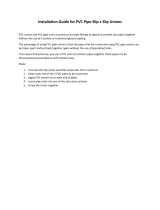
Models with PVC Socket Weld End Fittings
Pipe Support
Coupling
Union
PVC Pipe
Figure 6: PVC socket weld installation
1� Remove the two end ttings from the ow meter� Lubricate the O-rings and install the
ttings onto the ow meter�
LIQUID PIPE SEALANTS, PVC/CPVC PRIMERS AND PVC/CPVC CEMENTS CONTAIN
SOLVENTS THAT ARE NOT COMPATIBLE WITH POLYSULFONE PLASTIC. ALLOWING
LIQUID PIPE SEALANTS TO CONTACT THE PLASTIC FLOW METER WILL RESULT IN
WEAKENING OF THE FLOW METER BODY AND POTENTIALLY CAUSE FRACTURING
UNDER PRESSURE.
2� Prepare the ow meter PVC ttings and PVC pipe couplings with PVC cleaner/solvent�
3� Apply a thin layer of PVC glue to the PVC ow meter ttings� Orient the meter during
curing so that excessive glue will not run into or onto the ow meter� Connect all PVC
glue joints by inserting the pipes fully into their mating components and twisting 1/8
turn to provide adhesion� Allow sucient drying time�
4� Using the method outlined in steps 2 and 3, apply half of the PVC union to the ow
meter outlet tting�
5� Install the other half of the PVC pipe union to the outlet pipe�
6� Make sure the ow direction arrow on the ow meter corresponds with the system
ow direction� See Figure 4 on page 9� Lubricate the union O-ring and connect the
union together�
OTE:N Piping should be supported and aligned properly to avoid placing stress
on the flow meter body�
7� Slide the limit indicators to point to appropriate positions on the ow meter scale� To
remove the limit indicators, slide them fully toward the ow meter outlet
Page 11 October 2019 VAM-UM-00367-EN-03
w ww . . co m
information@itm.com1.800.561.8187

Installation
Models with Brass Sweat End Fittings
Pipe Support
Figure 7: Brass sweat fitting installation
1� Remove both brass ttings from the ow meter inlet and outlet� Remove O-rings from
the ttings�
2� Apply solder ux to the ow meter brass ttings and mating pipe surfaces�
3� Place the brass hex coupler onto the pipe with the thread facing the ow meter� Slide
the brass sweat tting onto the prepared pipe�
4� Sweat the ttings onto the pipe� Do not apply heat to the brass ow meter tting with
the plastic ow meter body or seals attached to the tting�
5� Repeat steps 3 and 4 for the other ow meter tting� Allow ttings to cool�
6� Lubricate the two O-rings removed in step 1� Place the O-rings onto the brass ttings�
7� Place the ow meter in between the two installed brass ttings� Make sure the ow
direction arrow on the ow meter corresponds with the system ow direction� See
Figure 4 on page 9� Thread the two brass hex couplers into the ow meter body�
8� Rotate the ow meter body so the scale can be conveniently viewed� Tighten the hex
couplers� Typically, only hand tightening is required�
9� Piping should be supported and aligned properly to avoid placing stress on the ow
meter body�
10� Slide the limit indicators to point to appropriate positions on the ow meter scale� To
remove the limit indicators, slide them fully toward the ow meter outlet�
Page 12 October 2019VAM-UM-00367-EN-03
w ww . . co m
information@itm.com1.800.561.8187

Installation
Models with Male, Metal or PVC Threaded End Fittings
Pipe Support
Figure 8: Male, metal or PVC threaded end fittings installation
1� Remove both ttings from the ow meter inlet and outlet� Remove the O-rings from
the ttings�
2� Apply Teon® tape to the male pipe thread connections�
3� Place the brass or stainless steel hex coupler onto the pipe with the threads facing the
ow meter�
4� Thread the ow meter ttings onto the mating pipe�
5� Tighten ttings by placing an open-end wrench onto the tting and a pipe wrench onto
the mating pipe�
6� Repeat steps 3…5 for the other ow meter tting�
7� Lubricate the two O-rings that were removed in step 1� Place the O-rings onto the
threaded ttings�
8� Place ow meter between the two installed ttings� Make sure the ow direction
arrow on the ow meter corresponds with the system ow direction� See Figure 4 on
page 9� Thread the two hex couplers onto the ow meter body�
9� Rotate the ow meter body so the scale can be conveniently viewed� Tighten hex
couplers� Typically, only hand tightening is required�
10� Piping should be supported and aligned properly to avoid placing stress on the ow
meter body�
11� Slide the limit indicators to point to appropriate positions on the ow meter scale� To
remove the limit indicators, slide them fully toward the ow meter outlet�
Page 13 October 2019 VAM-UM-00367-EN-03
w ww . . co m
information@itm.com1.800.561.8187

Installation
Models with Female, Metal Threaded End Fittings
Pipe Support
Union
Metal Pipe
Figure 9: Female, metal threaded end fittings installation
1� Apply Teon® tape to the male pipe thread connections�
2� Thread the inlet of the ow meter onto the appropriate pipe connection� Make sure the
ow direction arrow on the ow meter corresponds with the system ow direction� See
Figure 4 on page 9�
3� Tighten ow meter connection by placing an open-end wrench on the ow meter
metal connection adjacent to the pipe that is being attached� Tighten until snug� Make
sure ow meter scale is oriented for convenient viewing� Do not overtighten� Do not
back o or unscrew to rotate scale for better viewing�
4� Install a union tting at the outlet end of the ow meter�
DO NOT TIGHTEN THE FLOW METER BY WRENCHING FROM THE OPPOSITE FITTING, AS
THE METER BODY COULD CRACK.
5� Piping should be supported and aligned properly to avoid placing stress on the ow
meter body�
6� Slide the limit indicators to point to appropriate positions on the ow meter scale� To
remove the limit indicators, slide them fully toward the ow meter outlet�
Page 14 October 2019VAM-UM-00367-EN-03
w ww . . co m
information@itm.com1.800.561.8187

Flow-Alert Switch Options
FLOWALERT SWITCH OPTIONS
OTE:N All Flow-Alert switches are magnetically triggered� Switches cannot
be added to meters that were not ordered with the switching magnet�
Switches and flow meters are purchased separately�
Flow-Alert Latching Limit Switch
20
40
60
80
90
LPM
1. Only use Teflon tape to seal threaded fittings.
DO NOT use pipe dope.
2. DO NOT sweat fit adaptor fittings into a system
while mounted to the EZ-VIEW meter.
CAUTION
!
On
3%
Deadband
Off
Full
Scale
Switch
Contacts
0
FLOW DIRECTION
Figure 10: Latching switches
The AC and DC powered Flow-Alert modules consist of a relay circuit housed in a sealed
plastic enclosure� The modules have a normally open, dry relay contact that can be used to
directly control alarms, warning lights, relays or interface to a PLC� The relay is latched on as
the magnet inside the flow meter passes by the module, and remains latched on until the
magnet passes in the other direction, or power is interrupted� See Figure 10� The setpoint is
adjustable from 0…100% of full scale� Flow meters can be equipped with one latching limit
switch, either AC or DC�
Page 15 October 2019 VAM-UM-00367-EN-03
w ww . . co m
information@itm.com1.800.561.8187

Flow-Alert Switch Options
Flow-Alert Reed Limit Switch
20
40
60
80
90
LPM
1. Only use Teflon tape to seal threaded fittings.
DO NOT use pipe dope.
2. DO NOT sweat fit adaptor fittings into a system
while mounted to the EZ-VIEW meter.
CAUTION
!
On
15 - 25%
Of Scale
Off
Full
Scale
Switch
Contacts
0
FLOW DIRECTION
Figure 11: Reed switches
The reed switch Flow-Alert modules are available in three forms: Form A (normally open),
Form B (normally closed), and Form C (single-pole, double throw)�
Reed switches are housed in a sealed plastic enclosure for environmental protection� The
reed switch modules do not provide a latching function like the AC and DC powered units�
When the magnet inside the flow meter comes within proximity of the module, the reed
switch will change state� See Figure 11� The setpoint is adjustable from 0…100% of full scale�
Two reed switch Flow-Alert may be installed on a single flow meter but one must be set for
activation on increasing flow and the second must be set for activation on decreasing flow�
Page 16 October 2019VAM-UM-00367-EN-03
w ww . . co m
information@itm.com1.800.561.8187

Flow-Alert Switch Installation
FLOWALERT SWITCH INSTALLATION
Latching Switch
1� Install one end of the vibration locking kit onto the lpm side of the meter’s serrated rail
as shown in Figure 12�
2� Install the switch by placing the adjustment arm over the serrated rail from the inlet
end of the 1/2 in� (12 mm), 3/4 in� (19 mm) and 1 in� (25 mm) meters, or the outlet end of
the 1-1/2 in� (38 mm) or 2 in� (50 mm) meters� The direction of the connector and cable
assembly indicates whether the switch will activate on increasing ow (connector and
cable pointing down)� See Figure 13� Secure the other end of the vibration locking kit
and tighten after positioning�
Switches Positioned for Activation
on Increasing Flow
20
40
60
80
90
LPM
1. Only use Teon tape to seal threaded ttings.
DO NOT use pipe dope.
2. DO NOT sweat t adaptor ttings into a system
while mounted to the EZ-VIEW meter.
CAUTION
!
Switch Positioned for Activation
on Decreasing Flow
Figure 12: Vibration locking kit installation Figure 13: Switch position
3� The connector has four solder lugs labeled 1, 2, 3 and 4� Soldering wires to the terminals
rst requires disassembly of the connector as shown in Figure 14� The specic wiring
pinouts for each style latching switch are show in Figure 14�
OTE:N Before reassembly, label each wire with the corresponding lug position�
14
2
2
3
1
4
Polarity Pin
Solder Lug
Strain Relief Nut
Body
Top
View
Bottom
View
Key
1
32
4
1
3
2
4
DC Switch AC Switch
Pin Function Pin Function
1 Relay (NO) 1 Relay (NO)
2 DC+ 2 AC Supply
3 Relay Common 3 Relay Common
4 DC– 4 AC Supply
Figure 14: Wiring pinouts
Page 17 October 2019 VAM-UM-00367-EN-03
w ww . . co m
information@itm.com1.800.561.8187

Flow-Alert Switch Installation
4� Determine which direction the body of the connector should face� See Figure 15�
5� Snap the connector back together, pull the excess wire out of the strain relief, then
tighten the strain relief nut�
6� Plug the connector into the switch module and secure with the screw provided�
C A
B
Polarity Pin
Figure 15: Polarity pin
Latching Switch AC Wiring Configuration
WARNING
ALL WIRING SHOULD BE MADE IN ACCORDANCE WITH THE NATIONAL ELECTRICAL
CODE® AND MUST CONFORM TO ANY APPLICABLE STATE AND LOCAL CODES.
AC Conventional Connection
OTE:N The load must be within the specified contact rating range of 1A @ 30V
DC/500 mA @ 125V AC�
AC Line
AC Line
Switch Module
Contacts
Flow
Circuit
2 4
1 3
Fuse
0.1 A
AC
Load
1
Figure 16: AC conventional connection
Page 18 October 2019VAM-UM-00367-EN-03
w ww . . co m
information@itm.com1.800.561.8187

Flow-Alert Switch Installation
AC Conventional Secondary Connections
Figure 17 shows a secondary relay with a 115V AC coil integrated with the AC switch
module� This combination allows switching of loads up to the rating of the relay contacts�
OTE:N Load limited by relay contacts�
AC Line
AC Line
Switch Module
Contacts
Flow
Circuit
2 4
1 3
Fuse
0.1 A
AC Relay Contact
115 V Relay Coil
AC
Load
2
Figure 17: AC conventional secondary connections
DC Conventional Connection
DC Ground
10…30V DC
Switch Module
Contacts
Flow
Circuit
2 4
DC
Load
1 3
Fuse
0.1 A
1
Figure 18: DC conventional connection
DC Conventional Secondary Connections
Figure 19 shows a secondary relay with a DC coil integrated with the DC switch module� This
combination allows switching of loads up to the rating of the relay contacts�
OTE:N Load limited by relay contacts�
DC Ground
10…30V DC
Switch Module
Contacts
Flow
Circuit
2 4
1 3
Fuse
0.1 A
DC Relay Contact
DC Relay Coil
DC
Load
2
Figure 19: DC conventional secondary connections
Page 19 October 2019 VAM-UM-00367-EN-03
w ww . . co m
information@itm.com1.800.561.8187

Flow-Alert Switch Installation
Reed Switch
Install the switch on the flow meter by placing the adjustment arm over the serrated rail
from the inlet end of the 1/2 in� (12 mm), 3/4 in� (19 mm), and 1 in� (25 mm) meters, or the
outlet end of the 1-1/2 in� (38 mm) and 2 in� (50 mm) meters� Each meter accepts up to
two reed switches, and the switches for 1/2 in� (12 mm), 3/4 in� (19 mm) and 1 in� (25 mm)
meters must be installed before the meter is plumbed into the system�
Flow-Alert reed switches are available in three configurations: Form A (normally open),
Form B (normally closed), and Form C (SPDT)� See Figure 20 for wire color codes and
switch configurations�
WHITE
(Common)
BLACK
(Normally Closed)
RED
(Normally Open)
FORM C
FORM A
(Normally Open)
RED
BLACK
FORM B
(Normally Closed)
WHITE
BLACK
Figure 20: Form A, B and C
Page 20 October 2019VAM-UM-00367-EN-03
w ww . . co m
information@itm.com1.800.561.8187

Flow-Alert Switch Installation
Flow-Alert Reed Switch Adjustment
After the flow meter has been installed and the switch wired, the flow rate at which the
switch activates must be adjusted�
1� With the uid running through the meter, gently move the switch adjustment tab
outward until the switch body is free to slide up or down on the serrated rail� See
Figure 21�
2� Move the switch into position until the switch activates�
3� Release the switch adjustment tab(s) to set the switch position�
20
40
60
80
90
LPM
1. Only use Teflon tape to seal threaded fittings.
DO NOT use pipe dope.
2. DO NOT sweat fit adaptor fittings into a system
while mounted to the EZ-VIEW meter.
CAUTION
!
FLOW DIRECTION
5
10
15
20
25
GPM
2200 SOUTH STREET RACINE, WI 53404 PHONE 1-800-FLOW-888 FAX 1-800-775-3179
RIGHT
SIDE
LEFT
SIDE
Figure 21: Switch adjustment
WARNING
IF THE FLOW METER AND SWITCH ARE INSTALLED IN A CRITICAL APPLICATION, MAKE
SURE THE SYSTEM IS FAIL-SAFE. THE SWITCH SHOULD BE WIRED SO ANY SWITCH
FAILURE STOPS THE SYSTEM. FAILURE TO FAIL-SAFE THE SYSTEM MAY LEAD TO
SYSTEM DAMAGE AND/OR PERSONAL INJURY.
Page 21 October 2019 VAM-UM-00367-EN-03
w ww . . co m
information@itm.com1.800.561.8187
/