Protec TC-512A Installation, Operation & Maintenance Manual
- Type
- Installation, Operation & Maintenance Manual

INSTALLATION, OPERATION, MAINTENANCE MANUAL
KEEP THE MANUAL NEAR THE MACHINE ALL TIME
AND MAKE SURE ALL USERS HAVE READ THIS
FOLLOW THE INSTRUCTIONS CAREFULLY TO GRANT
THE MACHINE A CORRECT FUNCTION AND LONG
SERVICE LIFE.
TIRE CHANGER

2-26
Contents
1. Warning Sign-------------------------------------------------------------------------------2
2. Instruction-----------------------------------------------------------------------------------3
3. Safety Requirement----------------------------------------------------------------------3
4. Transport-------------------------------------------------------------------------------------4
5. Unpacking-----------------------------------------------------------------------------------4
6. Installation--------------------------------------------------------------------------------4-6
7. Operation--------------------------------------------------------------------------------6-10
8. Inflation---------------------------------------------------------------------------------10-11
9. Moving--------------------------------------------------------------------------------------11
10. Storage------------------------------------------------------------------------------------12
11. Scrapping---------------------------------------------------------------------------------12
12. Maintenance-------------------------------------------------------------------------12-14
13. Electric Connection Diagram------------------------------------------------------15
Assistant Arm (ASA80) Manual (Optional) ------------------------------------16-22

3-26
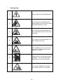
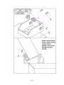
1. Warning Sign
1
Keep safety for electrified devices.
2
Do not put your leg between the
bead breaker are and the tire when
the bead breaking is used.
3
Do not put your hand between the
tire and turntable when machine is
operated.
4
Do not put your hand between the
M/D head and the tire.
5
It is forbidden to put your hand or
tools in the claws when they are
opened or closed.
6
Pedal down to the first gear direct
inflating;The nozzle whiff when
pedal down to the second gear.
7
Do not stand behind the vertical
arm when machine is operated.

4-26
2. Introduction
Thank you for purchasing our tire changers. The machine has been manufactured in
accordance with the very best quality principles. This manual is one integral part of
the product. Before using the tire changer, read carefully the warnings and
instructions contained in this manual since they provide important information on
operation safety and maintenance.
Keep this manual for future reference.
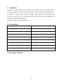
1). Technical Data
Max tire diameter
1100mm
Max tire width
13"/15"
Internal locking rim dimensions
11" -24"/12" -26"
External locking rim dimensions
13"-26"/14" -28"
Force on bead breaker blade
2500Kg
Working pressure
0.8-1.2Mpa
Power supply voltage
220V/110V/380V
Motor power
1.1kw/0.75Kw
Noise level in working conditions
<70dB
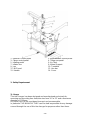
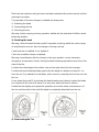
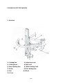
2). Description of Machine

5-26
1. Reverser control pedal
3. Clamp control pedal
5. Inflating pedal
7. Inflator box
9. Jaw
11. M/D head
13. Handle
2. Bead breaker control pedal
4. Tilting arm pedal
6. Air Tank
8. Wheel Support
10. Turntable
12. Hex bar
14. Cover
3. Safety Requirement
1). Usage
This tire changer has been designed and manufactured exclusively for
removing and mounting tires from/into rims from 10'' to 22'' and a maximum
diameter of 1100mm.
Any other use is to be considered incorrect and unreasonable.
In particular THE MANUFACTURE can't be held responsible for any damage
caused through the use of this tire changer for purposes other than those

6-26
specified in this manual, and therefore inappropriate, incorrect and
unreasonable.
2). General Safety Precautions
This tire changer may only be used by specially trained and authorized expert
personnel.
Any tampering and modification to the equipment carried out without the
manufacturer's prior authorization will free him from all responsibility for
damage caused directly or indirectly by the above actions.
The tire changer comes complete with instructions and warning transfers which are
designed to be long-lasting. If they should for any reason be damaged or destroyed,
please ask immediately for replacements from the manufacture.
Keep it away from combustible, explosive objectives, avoid strong light, sunshine,
and keep it in good ventilation.
Make sure to use original spare parts and accessories, installed by authorized
personnel according to manual.
Be careful if there are any dangers happen, stop the machine, contact manufacturer.
Non-operation personnel should be kept away from the machine.
Operators should be protected by protective (glove, eye-protection glasses,and
working-clothes) to avoid any accidental injuries.
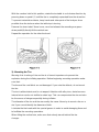
4. Transport
This tire changer must be transported in its
original packaging and kept in the position
shown on the package itself.
The packaged machine may be moved by
means of a fork lift truck of suitable capacity.
Insert the forks at the points shown at figure
below.
5. Unpacking

7-26
Use proper protection tools to unpack (gloves etc)
Check that the equipment is in perfect condition, making sure that no parts are
damaged or missing, if in doubt do not use the machine and contact your retailer.
Put the packing materials (plates, nails, screws, plastic bags) in safety place.
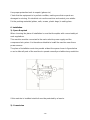
6. Installation.
1). Space Required
When choosing the place of installation is sure that it complies with current safety at
work regulations.
This machine must be connected to the mains electric power supply and the
compressed air system. It is therefore advisable to install the machine near these
power sources.
The place of installation must also provide at least the space shown in figure below
so as to allow all parts of the machine to operate correctly and without any restriction.
If this machine is installed outside it must be protected by a lean-to.
2). Commission

8-26
Before making the connections, check that the characteristics of your systems
correspond to those required by the machine.
Even small jobs done on the electrical system must be carried out by professional
personnel.
Connect the machine to the electrical network, which must be provided with line
fuses, a good earth plate in compliance with regulations in force and it must be
connected to automatic circuit breaker.
Warning: Should the tire changer be lacking in electric plug, so the user must set one,
which is at least 16A and which conforms to the voltage of the machine, in
compliance with the regulations in force.
3). Operation Test
When the pedal (1) is pressed down the turntable should turn in clockwise direction.
When the pedal is pulled up the turntable should turn in the anticlockwise direction.
Warning: if the turntable turns in the opposite direction to that shown, reverse the
wires in the three-phase plug.
Pressing the pedal (2) activates the bead breaker; when the pedal is released the
bead breaker returns to its original position.
Pressing the pedal (3) opens the four clamps; when the pedal is pressed again they
close.
Pressing the pedal (4) tilts the arm; when the pedal is pressed again it returns to its
working position.
When the pedal located on the left side of the machine is pressed down to the first
gear, air is released from the airline gauge. Gauge will indicate the pressure after
release of air.
When the pedal located on the left side of the machine is pressed down to the
second gear, air is released from the airline gauge along with a powerful jet from the
nozzles located on the turntable clamps.
Don't lean on the turntable during this operation, possible dirty dust on the turntable
could offend the operator's eyes. For the same reason, be carefully as not to
accidentally push the inflating pedal while working.
7. Operation

9-26
Don’t use the machine until you have read and understood the entire manual and the
warnings it provides.
The operation of the tire changer is divided into three parts:
1). Breaking the bead
2). Demounting the tire
3). Mounting the tire;
Warning: before carrying out any operation, deflate the tire and take off all the wheel
balancing weights.
1). Breaking the bead
Warning: when the bead breaker pedal is operated, anything within the action range
of bead breaker arm can be in the danger of being crushed.
Check that tire is deflated, if not, deflate it.
Close the turntable clamps completely.
Warning: bead breaker with the clamps in the open position can be extremely
dangerous for operator's hands; during the bead breaking operations never touch the
side of the tire.
Position the wheel against the rubber stop on the right side of the tire changer.
Position the bead breaking blade against the tire bead at a distance of about 1 cm
from the rim. Pay attention to the blade, which must be correctly onto the tire not onto
the rim.
Press down the pedal (2) to activate the bead breaker and release it when the blade
has reached to the end of its travel or in any case when the bead is broken.
Rotate the tire slightly and repeat the operation around the entire circumference of
the rim and from both sides until the bead is completely detached from the rim.
2). Demounting the Tire

10-26
Before any operations remove the old wheel balancing weights and check thatthe tire
is deflated.
When tilting the vertical arm, be sure that nobody stands behind the tire changer.
Press down pedal (4), tilt the vertical arm, and clean the turntable.
Spread the grease onto the tire bead.
Failure to use the grease risks causing serious damage the tire bead.
When clamping the tire, never have your hands under the tire. To clamp the tire
correctly, position the wheel exactly at the center of the turntable.
Rim locking from outside:
Position the clamps according to the reference mark on the turntable by pressing the
pedal down to its intermediate position.
Place the tire on the clamps and, keeping the rim pressed down, press the pedal (3)
as far as it will go.
Rim locking from inside:
Position the clamps so that it they are completely closed.
Place the tire on the clamps and press down the pedal (3) to open the clampsand
thereby lock the rim.
Make sure the rim is firmly fixed to the clamps.
Press the pedal (4), restore the vertical arm to its working position.
Push out the locking button in the handle, release hex bar.
Lower the hex bar until the mounting tools rests against the edge of the rim.
Then lock it using the locking button in the handle. This way the mounting armis
locked in a vertical and horizontal direction and the mounting head is automatically
moved to a distance of about 2mm from the rim.
Do not put hands on the wheel, when moving the mounting arm to its working
position your hand could be crushed between the rim and the mounting head with the
crowbar inserted between the bead and the front section of the mounting head, move
the tire bead over the mounting head.
WARNING: In order not to damage the inner tube, it there is one, it isadvisable to
carry out this operation with the valve 10cm to the right of the mounting head.
Chains, bracelets, loose clothing or foreign objectives in the vicinity of moving
parts can cause danger to the operator.

11-26
With the crowbar held in this position, rotate the turntable in a clockwise direction by
pressing down on pedal (1) until the tire is completely separated from the wheel rim.
To prevent industrial accidents, keep hands and other parts of the body as far as
possible from the tool arm when the table top is turning.
Remove the inner tube if there is one, need not release the mounting arm,press
down pedal(4),directly tilt the vertical arm.
Repeat the operation for the other tire bead
3). Mounting the Tire
Warning: this checking of tire and rim is of utmost importance to prevent tire
explosion during the inflating operation. Before beginning mounting operation make
sure that:
The tire and the cord fabric are not damaged. If you note the defects, do not mount
the tire.
The rim is without dents and is not warped. Attention with alloy rims, dents because
internal micro-cracks not visible to naked eye. This can compromise the rim and also
be the source of danger especially during inflation.
The diameter of the rim and tire are exactly the same. Never try to mount a tire on a
rim if you cannot identify the diameter of both.
Lubricate the tire beads with the special grease in order to avoid damaging them and
to facilitate the mounting operations.
When tilting the vertical arm, make sure that nobody stands behind the tire
changer.

12-26
When you are working with the rims of the same size, it is not necessary always to
lock and unlock the hex bar. Just tilt and restore the vertical arm with the horizontal
arm and mounting arm locked.
Move the tire so that the bead passes below the front section of the mounting head
and is brought up against the edge of the rear section of the mounting head itself.
Keep the tire bead pressed down into the wheel rim channel with your hands, press
down on the pedal (1) to rotate the turntable clockwise. Continue until you have
covered the whole circumference to the wheel rim; insert the inner tube (if there is
one).
Repeat the same operations to mount the upper side of the tire.
WARNING: dismounting and mounting are always done with the clockwise turntable
rotation. Anticlockwise rotation is used only to correct operator's errors or if the
turntable stalls.
8. Inflation
The greatest attention is called for when inflating the tires. Keep strictly to the
following instructions since the tire changer is not designed and built to protect the
user (or anyone else in the vicinity of the machine) if the tire burstsaccidentally.
A burst tire can cause serious injury or even death of the operator.
Check carefully that the wheel rim and the tire are of the same size.
Check the state of wear of the tire and that it has no defects before beginning the
installation stage.
Inflate the tire with brief jets of air, checking the pressure after every jet.
Maximum inflating pressure is 0.8MPa.i n any
case never exceed the pressure recommended
by the manufacturer.
Keep your hands and body as far away as
possible from the tire.
1). Bead Blasting

13-26
There is a pedal on the side of the machine.
This pedal has two positions. The first
position is for the inflation for the tire with tube.
Step the pedal lightly for several times during
the inflation. Make sure the reading on the
gauge does not exceed the manufacturer’s
limit 。
The second position is for the inflation for the tubeless tire, step the pedal down fully
to the bottom, and then make the pedal to the first position to continue the inflation.
Make sure that the reading on gauge doesn’t exceed the manufacturer’s limit.
Warning: the operator should wear safety goggles when operating.
2). Inflating tire using airline gauge:
Inflate a tire proceed as follows:
Connect the airline gauge fitting to the tire valve.
Make a last check to be certain that the tire and rim diameter correspond.
Between air jets, constantly check the pressure until required pressure has been
reached explosion hazard!
Never exceed 0.8MPa, when inflating tire on a fixed position. If a higher inflating
pressure is required remove the wheel from the turntable and continue the inflation
inside a special protection cage (commerciallyavailable).
Never exceed the max. Inflating pressure given by the tire manufacturer.
Always keep hands and body back from inflating tire.
Only specially trained personnel are allowed to perform these operations .do not
allow other persons to operate or to stay near the tire changer.

14-26
9. Moving
Move the tire changer you need a fork-lift truck.
Disconnect the pneumatic and electric power supplies.
Apply leverage to one side of the base so as to raise it slightly from the floor,Insert
the forks of the truck under the base and slide the tire changer onto them.
Set the tire changer down in its new position.
10. Storage
In the event of storage for long periods of time, make sure to disconnect all sources
of power and grease the clamp sliding guides on the turntable to prevent from
oxidizing.
11. Scrapping
If you decide scrape the machine, be sure to make it inoperative bydisconnecting it
from all sources of power.
Remove all non-ferrous materials and dispose of them as prescribed bynational law.
Collect the oil and dispose of it at an authorized point as prescribed bynational law.
Scrape the rest ferrous material.
12. Maintenance
1) General warning
Unauthorized personnel may not carry out maintenance work.
Regular maintenance as described in the instructions is essential for correct
operation and long lifetime of the tire changer.

15-26
If maintenance is not carried out regularly, the operation and reliability of the machine
may be compromised, thus placing the operator and anyone else in the vicinity at risk.
Before carrying out any maintained work, disconnect the electric and pneumatic
supplies. Moreover, it is necessary to break the bead load less 3-4 times in order to
let the air in pressure go out of the circuit.
Defective parts must be replaced exclusively by expert personnel using the
manufacture's spare parts.
Removing or tampering with safety devices (pressure limiting and regulating valves)
represents a contravention of safety regulations. In particular, the manufacturer shall
not be held responsible for complaints deriving from the use of spare parts made by
other manufacturers or for damage caused by tampering or removal of safety
systems.
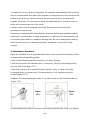
2). Maintenance Operations
Clean the turntable once a week with diesel fuel so as to prevent the formation of dirt,
and grease the clamp sliding guides.
Carry out the following operations at least once every 30 days:
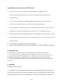
Check the oil level in the lubricator tank. If necessary, fill up by unscrewingscrew 2;
only use SAE30 oil (figure 12-1)
Check that a drop of oil is injected into the reservoir, every 3-4 times the pedal
is pressed down, one drop every 3-4 times pressing. If not, regulate using the
screw(2)(figure 12-1).
Retighten the clamp tightening screws (1) and the screws on the turntable slides (2).
(Figure 12-2)
Figure Figure
12-1 12-2
If the turntable doesn't work, it may be caused by loose drive belt, check it as follows:

16-26
Before any operations, please disconnect the electric power supplies.
Remove the left side body panel of the tire changer. Tighten the drive belt by means
of the special adjusting screw (1) on the motor support.
It is necessary to adjust the screw(1) in the locking plate of the mounting arm,if the
mounting head doesn't lock or it doesn't rise from the rim of 2mm necessary for
working.(figure 12-4)
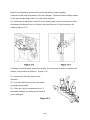
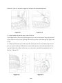
If clamps or bead breaker open/close slowly, it is necessary to clean or replace the
silence, and proceed as follows :( Figure 12-5)
(1). Remove the left side panel of the
machine.
(2). Unscrew the silencer put on the clamp
opening/closing pedal.
(3). Clean by a jet of compressed air or, if
damaged, replace by referring to the spare
parts catalogue.
Figure 12-5

17-26
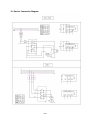
13. Electric Connection Diagram

18-26
Assistant Arm (AL320) Operation
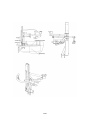
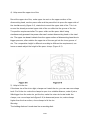
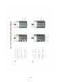
1. Structure
1). Guiding Bed 2). Adjusting Screw
3). Gliding Block 4). Main Arm
5). Block Holding Arm 6). Roller Holding Shaft
7). Roller 8). Disc Holding Arm
9). Disc 10). Block
11). Cone

19-26
2. Safety requirement
Any other use is to be considered incorrect and unreasonable.
Read this manual carefully before using it; Make sure that you understand how to
operate this machine and the notices. THE MANUFACTURE can't be held
responsible for any damage caused through the use of this machine for purposes
other than those specified in this manual, and therefore inappropriate, incorrect and
unreasonable.
General safety precautions
This machine may only be used by specially trained and authorized expert personnel.
1). Any tampering and modification to the equipment carried out without the
manufacturer's prior authorization will free him from all responsibility for damage
caused directly or indirectly by the above actions.
2). Keep it away from combustible 、explosive objectives; avoid strong light,
sunshine, and good ventilation.
3). Make sure to use original spare parts and accessories.
4). Installed by authorized personnel according to manual.
5). be careful if there are any dangers happen stop the machine, contact
manufacturer.
6). Non-operation personnel should be kept away from the machine.
7). Operators should be protected by protective materials (glove, eye-protection
glasses, and working-clothes) to avoid any accidental injuries.
3. Unpacking
1). Use proper protection tools to unpack (gloves etc)
2). Check that the equipment is in perfect condition, making sure that no parts are
damaged or missing, if in doubt do not use the machine and contact your retailer.
3). Read the packing list carefully; check if there is any missing, if in doubt contact
your retailer.
4). Put the packing materials (plates, nails, screws, plastic bags)in safety place.
5). Deal with any contamination or dissolvable materials contained in the
packing box according to local laws.

20-26
Page is loading ...
Page is loading ...
Page is loading ...
Page is loading ...
Page is loading ...
Page is loading ...
-
 1
1
-
 2
2
-
 3
3
-
 4
4
-
 5
5
-
 6
6
-
 7
7
-
 8
8
-
 9
9
-
 10
10
-
 11
11
-
 12
12
-
 13
13
-
 14
14
-
 15
15
-
 16
16
-
 17
17
-
 18
18
-
 19
19
-
 20
20
-
 21
21
-
 22
22
-
 23
23
-
 24
24
-
 25
25
-
 26
26


Protec TC-512A Installation, Operation & Maintenance Manual
- Type
- Installation, Operation & Maintenance Manual
Ask a question and I''ll find the answer in the document
Finding information in a document is now easier with AI
Other documents
-
 Toolots tire changer User manual
-
Ranger R980XR Owner's manual
-
 Wakeman Outdoors HW4700058 Operating instructions
-
-
-
Butler HP441SQ.22 Owner's manual
-
TUXEDO TC-430 Dimensions Guide
-
 Butler HP641SD.24 Pro Owner's manual
-
Zipper Mowers ZI-RMM94H-400V Operating instructions
-
 Atlas Equipment Atlas TC221 Assembly Manual


