MUTOH VJ-1626UH Installation guide

Category
Print & Scan
Type
Installation guide

MUTOH VJ-1626UH is a full-color inkjet printer designed for professional printing applications. With its advanced technology and versatile features, it offers high-quality output, efficient operation, and a wide range of printing possibilities. From producing stunning graphics and signage to creating custom labels and decals, the MUTOH VJ-1626UH is a powerful tool for various industries, including advertising, design, and manufacturing.

MUTOH VJ-1626UH is a full-color inkjet printer designed for professional printing applications. With its advanced technology and versatile features, it offers high-quality output, efficient operation, and a wide range of printing possibilities. From producing stunning graphics and signage to creating custom labels and decals, the MUTOH VJ-1626UH is a powerful tool for various industries, including advertising, design, and manufacturing.

1 VJ1626UHE-I-01
VJ-1626UH INSTALLATION MANUAL
Please read this manual
before using
Thank you for purchasing a MUTOH product.
This manual explains the steps for unpacking,
mounting and basic installation before using the
MUTOH Full-color inkjet printer VJ-1626UH.
This manual is intended for owners, installers, and
users of this product.
Understand the contents and instructions in this
manual before installing this product.
Installation flow chart
The broad steps for installation are shown below.
There are instructions for each section beginning on
the next page.
1 Unpacking boxes
1.1 Unpacking the printer box
1.2 Unpacking the stand box and
the Media-feed table F and R
boxes
 
2
Confirming bundled items
2.1 Items in the printer box
2.2 Items in the accessory box
2.3 Items in the stand box
2.4 Items in the Media-feed
table
(optional)
box
3 Assembling
3.1 Assembling the stand
 
3.2 Attaching the stand
 
3.3 Detaching fastening materials
3.5
Assembling the Media-feed table
(optional) 
4 Installation
4.1 Installation environment
4.2 Installation procedure
5
Connecting the power cable
6
Turning the power ON/OFF
7 Product activation
8 Initial ink filling 
9
Loading media
9.1 Loading rigid media
9.2 Loading roll media
10
Checking the printing condition
11 Manual composition
VJ-1626UH INSTALLATION MANUAL
VJ1626UHE-I-01 2
8
1
2
4
3
6
5
89
7
9
7
10
3
1
2
3
5
4
5
6
6
11
1
2
3
4
5
6
7 8
9
10
12 13
11
12
6
10
5
4
7
8
9
13
14
3
12
11
2
1
1 Unpacking boxes
Procedures for unpacking boxes are explained.
This printer package consists of four boxes: Main
body, Stands, and Media-feed table (two separate
optional boxes).
Make sure to unpack this product with
four persons or more.
While taking out the printer from the box,
make sure to remove the vinyl sheet.
1.1 Unpacking printer box
Unpack the printer box in accordance with the following steps.
1. Carry the box to where you will unpack it.
2. Remove the bands.
3. Open the box and take out the following components.
Printer main body
Accessory box
1.2 Unpacking Stand, Media-feed
table
Follow the procedure below to unpack the Stand,
Media-feed table F, and Media-feed table R.
*Media-feed tables F and R are optional.
1. Carry the box to where you will unpack it.
2. Open the box and take out the components.
2
Confirming bundled items
After unpacking, please confirm that the product has
not damaged and no components are missing.
If any items are damaged or missing, contact
MUTOH local dealer.
2.1
Items in the printer box
2.2 
Items in the accessory box
2.3 Items in the stand box
2.4 Contents of Media-feed table
(optional) box
(half side)
No. Name Q'ty
1 Leg part (Right) 1
2 Leg part (Left) 1
3 Connector bar 1
4 Base parts 2
5 Waste fluid tank holder 1
6 Hexagon socket head cap screws 8
7 Waste fluid tank holder fixing screws 4
8 Butterfly screws 8
9 Hexagonal wrench 1
1 Frames 1
2 Leg (left) 1
3 Leg (right) 1
4 Reinforcement 1
5 Rails (fixed) 1
6 Stopper 1
7 Installation plate (Left) 2
8 Installation plate (Right) 2
9 Hexagon socket head cap screw 8
10 Screw 8
11 Lug screw 1
12 Hexagonal spanner 2
13 Hexagonal wrench 1
No. Name Q'ty
1 Clean stick 10
2 Rubber gloves 100
3 Plastic gloves 100
4 Goggles 1
5 Flushing box sponge 10
6 Spirit level 1
 7 Paper towel(Lint-free cloths) 5
8 Waste fluid tank 1
 9 Tray 1
10 Operation Manual CD 1
11 Notes for using the dedicated ink 1
12 Notification sheet (Japanese/English) 1
13 Light-shielding cover 1
14 Light-shielding tube 1
No. Name Q'ty
No. Name Q'ty
1 Printer main body 1 set
2 Accessory box 1
3 Installation Manual (this manual) 1
No. Name No. Name
2
3
4
5
1
6  
7
8 
Accessory box
Installation Manual
(this manual)
Printer main body
9 
10
11
Top cover
Top board
Outer board
Center board
Side board A
Side board B
Cushion (Left)
Cushion (Right)
CAUTION
NOTE
VJ-1626UH INSTALLATION MANUAL
3 VJ1626UHE-I-01
1
2
3
4
Front
1
2
3
4
Front
Front
1
2
3
3
2
1
1
1
2
1
3
1
1
2
2
1
1
2
2
2
3
3
3
3
3
3
1
2
3
4
Front
3 Assembling
This section explains how to assemble the printer.
3.1 Assembling the stand
Follow the procedure below to assemble the stand.
1. Follow the procedure below to assemble the right
stand.
a. Attach the right leg part to the right base part so
that four screw holes in the base part are at the front.
b.Tighten two hexagon socket head cap screws using a
hexagonal wrench.
2. Assemble the left stand in the same way as in Step 1.
3. Fasten the connector bar to the right stand using
two hexagon socket head cap screws.
Attach the connector bar with the groove facing
the rear as shown below.
4. Fasten the connector bar to the left stand in the
same way as in Step 3.
5. Attach the waste fluid tank holder to the right
stand using four waste fluid tank holder fixing
screws.
6. Shake the stand to make sure that each part is
firmly attached.
When the printer is wobbly, loosen the hexagon
socket head cap screws once and then tighten
them again.
3.2 Attaching the stand
Follow the procedure below to attach the stand to the
printer.
1. Turn the four adjusters as shown below to prevent
the stand from moving.
2. Insert the two transfer stays into the right and left
transfer brackets, lift the printer with four or more
people and place it on the stand.
3. Remove the two transfer stays and fasten the
printer to the stand using eight butterfly screws.
4. Shape the light-shielding cover.
To shape the light-shielding cover, use double-
sided adhesive tape (already attached to the
light-shielding cover) to glue each tab to the
corresponding side
5. Attach the light-shielding tube to the waste fluid
tube.
Fix the light-shielding tube to the rubber bush.
4. Follow the procedure below to attach the waste fluid
tank.
a. Place the waste fluid tank in the waste fluid tank
holder.
b. Attach the waste fluid tube to the tank.
c. Insert the waste fluid sensor cable into the
connector on the bottom of the printer.
1
2
2
1
2
3
4
5
2
1
3
No.   Name   No. Name
1 Light-shielding cover  3  Double-sided adhesive
tape (Flip side)
No.   Name   No. Name
1 Waste fluid tube    3   Rubber bush
2 Light-shielding tube
No. Name     No.   Name
3  Waste fluid tank holder
fixing screws
2   Waste fluid tank holde
1    Leg part (Right)
No.   Name   No. Name
1 Transfer stays    3   Butterfly screws
2 Stand
No. Name     No.   Name
3 
Hexagon socket head cap screws
2     Base part
4  Screw holes in base part
1    Leg part (Right)
No. Name     No.   Name
3 
Hexagon socket head cap screws
2     Base part
4  Screw holes in base part
1    Leg part (Left)
No. Name     No.   Name
3 
Hexagon socket head cap screws
2    Connector bar
4  Groove in connector bar
1    Stand (Right)
No. Name     No.   Name
3   Stand
2   Transfer brackets
1    Transfer stays
No. Name     No.   Name
2   Stand
1    Adjusters
No. Name     No.   Name
3 Hexagon socket head
cap screws
2   Connector bar
1   Stand (Left)
Assemble this printer with 4 persons
or more.
CAUTION
No.   Name   No. Name
3   Waste fluid tube
2    Waste fluid tank
4  Waste fluid sensor cable
5 
Waste fluid sensor connector
1  Waste fluid tank holder
VJ-1626UH INSTALLATION MANUAL
VJ1626UHE-I-01 4
1
2
4
3
4
Front
Firmly insert the protruding portions of the legs
to the holes of the Frame to fix it.
Front
1
2
2
Front
2
1
3
2
1
7. Attach the light-shielding cover to the waste fluid
tank.
Insert the light-shielding cover inside the waster
fluid tank holder.
1
2
2
3.3 Detaching fastening materials
This printer has fastening materials in the place shown
below.
1. Remove all tapes from each cover.
2. Open the front cover and remove all protection
materials fixed with tape.
3. Open the right Maintenance cover, and remove all
the packing materials that are fixed with tape.
4. Remove a screw from the head unit fastening
material (metal plate) and remove the material.
5. Open the left maintenance cover, then place the tray.
2
3
1
1
2
1
No. Name    No.     Name
           
2
Screw
1
Head unit
3
Head unit fastening
material (metal plate)
No.    Name      No.   Name
1  Maintenance cover  2     Tray
No.    Name      No.   Name
1  Light-shielding cover  2  Waste fluid tank holder
3.4 Assembling the Media-feed table
(optional)
Follow the procedure below to assemble the
Media-feed table.
3.4.1 
Assembling the Media-feed table
1. Use hexagon socket head cap screws (4 pieces) to
fix the reinforcement between the legs (right and
left).
2. Place the Frame on the legs and fix it with four
hexagon socket head cap screws.
3. Use the screws (4 pieces) to fix Rails (fixed) on
the center of Frame.
When installing Rails (fixed), make sure that
the left and right rails are facing the same way.
4. Use the lug screw to fix Stopper on Frame
Install Stopper on the side of rail retaining screw.
Install Stopper so that the curved part matches
Frame.
5. Use the screws (2 pieces each) and fix Installation
plates (R and L) on Frame.
Install Installation plates on the opposite side of rail
fixing screw.
6. Assemble the other side of Media-feed table in the
same way
No. Name No. Name
1 Rails(fixed)
2 Frame
3 Screw
No.   Name     No.   Name
3    
Reinforcement
4 
Hexagon socket head cap screws
2      Leg (right)
Place the convex sections of the legs (right and left)
along the notch of the reinforcement to assemble.
No.   Name     No.   Name
1     
Leg (left)
1  Leg (left), leg (right)  2   Reinforcement
No.    Name     No.   Name
3     Lug screw
4  Rail retaining screw
2      Stopper
1     Frame
No.    Name     No.   Name
3    Frame
4    Screw
2   Installation plates (L)
1  Installation plates (R)
No. Name
1 Frame
No. Name
2 Hexagon socket head
cap screws
1
2
3
4
2
3
1
3
3
3
1
2
                                                                     VJ-1626UH INSTALLATION MANUAL
5 VJ1626UHE-I-01
4.2.2 Installing the Media-feed tables
(optional)
When using rigid media on this printer, use
Media-feed table (optional).
Follow the procedure below to install Media-feed
table.
The following items are required for installing
Media-feed table:
• Spanner: Accessories for Media-feed table
• Level: provided with the printer
(1)Rear side
1. Loosen the fixing levers on the right and left side
of the rear. Set the distance between the roll media
holders wider than the roll media width.
2. Loosen retaining screws of Media-feed table, and
slowly level the table.
3. Tighten the leveling screws of Media-feed table (2
places, both sides), and fix the table.
1
2
  No. Name     No.   Name 
1  Media-feed table  2   Leveling screw 
WARNING
When Using the roll media for “10 Checking the
printing condition”, you do not need to install
Media-feed table.
No.      Name      No.    Name
3    Fixing Lever
2  Roll media holderR
(1) When using the Media-feed table
(2)
When not using the Media-feed table
4.2 Installation procedure
Install this product to the installation place in
accordance with the list shown below.
4.2.1 Installing the printer main unit
1. Carry the printer to the installation place.
2. Turn the following adjusters in the direction as
shown below to prevent the printer from moving.
Stands: adjusters (4)
3. Set the level on the right and left platens and
adjust so that the printer stays flat.
4. Confirm that the waste fluid valve is closed.
4 Installation
Procedures and environment for installing this product
are explained.
4.1 Installation environment
Install this product to the appropriate place with
reference to the following.
Do not install the printer in the
following places where there is a
possibility that the printer may be
damaged or might fall or be fallen by
chance.
On a shaky stand
Slanting location
Places where vibration of other
machines etc. is transmitted.
Do not step on the printer or place
heavy things on top of it.
It may cause an injury if the printer
falls down.
Do not block the vent by covering the
printer with cloths, such as a blanket or
tablecloth. If the vent is blocked, heat
may accumulate inside the printer and
it may cause fire.
Do not install the printer in a location
that has high humidity or is dusty.
It could lead to electric shock and fire.
4.1.1
Installation environmental condition
Select an installation location in accordance with the
table below.
For temperature and humidity, avoid locations
such as the following. There is a possibility that
the print quality will be affected.
Places where temperature or humidity may
rapidly change, even though within the required
conditions.
Places that receive direct sunlight, increased
illumination or direct air, for example from an air
conditioner.
To keep the temperature and humidity constant,
install this product in a location where the air
condition is adjustable.
4.1.2 Installation space
Install on a level floor which meets the following condition.
It has enough strength to support the weight of the
printer and the stand.
For the weight of the printer and the stand, refer to
the Operation Manual.
More than 2940 Pa (300 kg/m
2
)
Power
Specifica-
tion
Environm-
ental
conditions
Floor strength of
installation place
Rated
voltage
Frequency
Range
50/60Hz ± 1Hz
Power
capacity
Change
rate within
warranty
Operative
condition
Printing
accuracy
coverage
Temperature: 20 °C to 32 °C
Humidity: 40 % to 60 %, No Condensation
Temperature: 22 °C to 30 °C
Humidity: 40 % to 60 %
Without condensation
Temperature: within 2 °C per hour
Humidity: within 5 % per hour
WARNING
NOTE
NOTE
100V-120V: Total of 4.0A
200V-240V: Total of 2.0A
AC100-240V
When fixing the leveling screws, hold
the frame while pressuring the rubber
foot, and then turn the
screw until it doesn't turn any further.
1
2
3
No.     Name   No. Name
3    Frame
2    Leveling screw
1   Media-feed table
1  Roll media holderL
No.    Name   No.   Name
No. Name No.   Name
1     Adjuster      2    Stand
1    Level      2    Adjuster
1    Waste fluid valve
NOTE
1,000mm 1,000mm
1,000mm1,000mm
2,698mm
4,698mm
2,730mm
4,730mm
1,000mm
1,000mm
1,000mm
1,000mm
4,698mm
818mm
2,818mm
2,698mm
No.     Name   No. Name
1
1
2
1
2
2
1
1
1
1
3
1
2
3
2
VJ1626UHE-I-01 6
VJ-1626UH INSTALLATION MANUAL
1
2
1
2
1
6mm
2
1
1
2
2
1
1
1
2
1
8. Turn the screw of Media-feed table's caster (the
one further from the printer) with a spanner, and
adjust the slant.
Make sure that the position of the level's air
bubble is at the same position as when you place it
on the printer.
9. Adjust the slant on the other side in the same way.
(2)Front side
1. Loosen retaining screws of Media-feed table, and
slowly level the table.
2 . Tighten the leveling screws of Media-feed table (2
places, both sides), and fix the table.
3. Insert the positioning guide of Media-feed table
into the square hole of Paper guide F.
If the height of the positioning guide does not
match the square hole, turn the screw of
Mediafeed table's caster, and adjust the height.
(See step 4.)
4. Turn the screws of Media-feed table's caster (2
places, closer to the printer) with a spanner so that
the top side of Media-feed table's positioning
guide slightly touches the top side of Paper guide
F's square hole.
5. Place the level at the edge of printer's platen, and
check the position of the air bubble.
6 . Place the level on the frame of Media-feed table.
Place the level on the same side as when you
placed it on the printer.
7. Turn the screw of Media-feed table's caster (the
one further from the printer) with a spanner, and
adjust the slant.
Make sure that the position of the level's air
bubble is at the same position as when you place it
on the printer.
8. Adjust the slant on the other side in the same way.
Caster of Media-feed table has 2 types of
screws. Turn the bottom screw.
Turn the screw clockwise to raise Media-
feed table.
  No. Name     No.   Name 
1  Screws on Caster 2  Positioning guide 
  No. Name     No.   Name 
1    Level        2     Platen
  No. Name     No.    Name 
1 Frame of Media-feed table 2  Level
  No. Name     No.   Name 
1  Screws on Caster 2  Level
If Media-feed table's slanted, media may
touch Print head, and Print head may break.
  No. Name    No. Name 
1  Scrwews on Casters 2  Level 
  No. Name     No.   Name 
1  Media-feed table 2  Leveling screw 
  No. Name     No.   Name 
1 Media-feed table 2  Leveling screw
  No. Name     No.   Name 
1  Positioning guide   2  Square hole
1
2
1
2
When fixing the leveling screws, hold the frame
while pressuring the rubber foot, and then turn the
screw until it doesn't turn any further.
NOTE
CAUTION
CAUTION
1
2
2
1
4. Insert the positioning guide of Media-feed table
into the square hole of Paper guide R.
If the height of the positioning guide does not match
the square hole, turn the screw of Mediafeed
table's caster, and adjust the height. (See step 5.)
5. Turn the screws on the caster of Media-feed table
(2 places, ones closer to the printer) with a spanner.
Adjust so that there is a 6 mm gap between the top
side of the square hole of Paper guide R and the
top side of the positioning guide.
6. Place the level at the edge of printer's platen, and
check the position of the air bubble.
7 . Place the level on the frame of Media-feed table.
Place the level on the same side as when you  
  placed it on the printer.
Caster of Media-feed table has 2 types
of screws.Turn the bottom screw.
Turn the screw clockwise to raise Media
-feed table.
  No. Name     No.   Name 
1   Positioning guide  2    Square hole
  No. Name     No.   Name 
1  Screw on the casters 2  Positioning guide 
  No. Name     No .   Name 
1    Level       2     Platen
1    Level     2   Frame of Media-feed table
  No. Name  No.   Name 
1
2
2
1
2
1
6mm
2
1
1
2
WARNING
1
2
1
7 VJ1626UH-I-01
                                                                    VJ-1626UH INSTALLATION MANUAL
1
2
6 Turning the power ON/OFF
This section explains how to turn the printer
ON/OFF, and how to start the sleep mode.
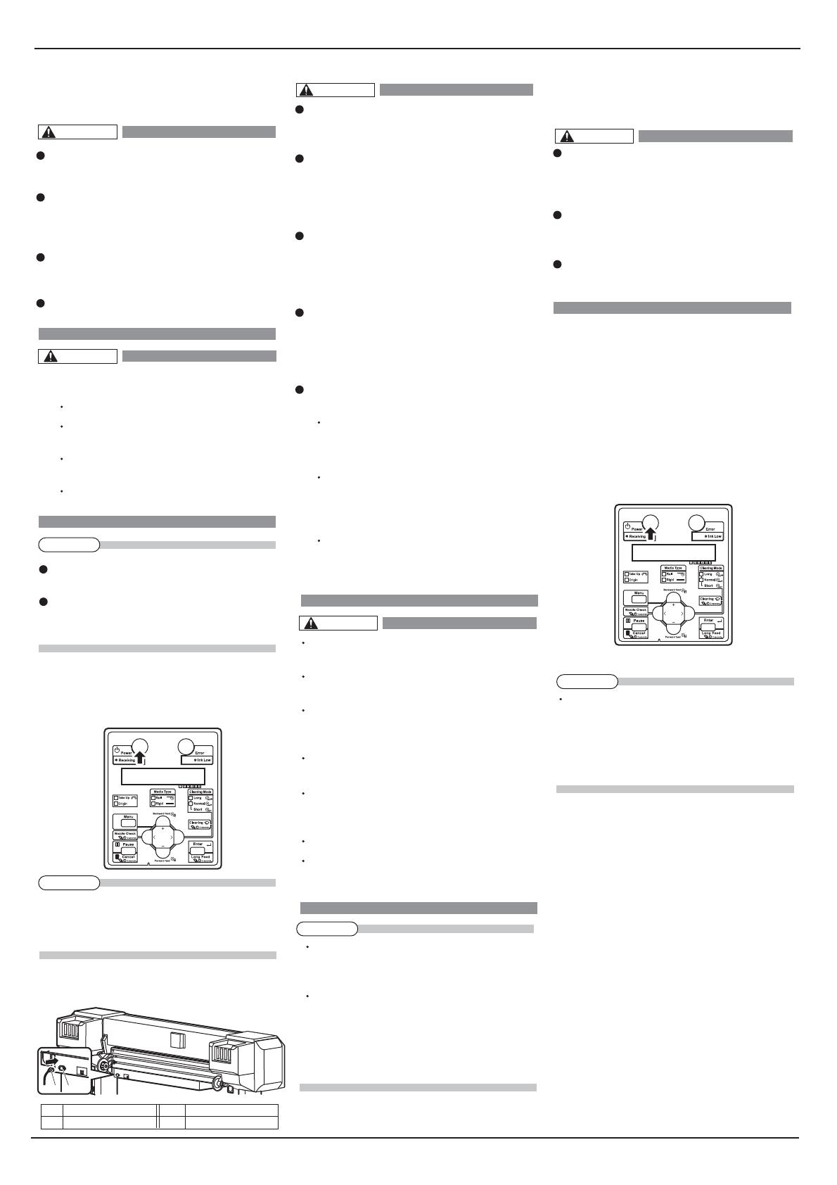
6.1 Turning the power ON
Follow the procedure below to turn the power ON.
1. Press the [Power] key on the operation panel to
turn ON the printer.
The Power lamp on the operation panel lights up
in blue.
The printer starts initial operation.
When the initial operation is complete, the printer
enters Normal.
If there is a problem during the initial
operation, a message is displayed on the
operation panel and the printer may stop
operating.If operation stops, refer to "7
Troubleshooting"and deal with the
problem.
3. Insert the power cable plug firmly in the socket.
Do not pull out or insert the power plug
with a wet hand.
This could lead to an electric shock.
Make sure to use only the specified
power supply (AC 100 V to 120 V or AC
220 V to 240 V). If a power supply other
than the specified voltage is used, it could
cause an electric shock and fire.
Take power for the printer directly from
the power socket (AC 100 V - 120 V or
AC 220 V - 240 V).Do not use multiple
plugs on the same socket.This could
generate heat and might cause fire.
Be sure to use a dedicated power socket
with earth wire for the power supply, and
connect it to the earth wire.
If the earth wire is not connected, an
electric shock or fire may occur.
Do not connect an earth wire to the
following places.
Gas pipe
There is a possibility of ignition and
explosion.
Earth wire of telephone cables and
lightning rods
Heavy current might flow whenever
lightning strikes.
Water pipe and faucet
The earth might not work if a plastic pipe
is connected in the middle of the metal
pipe.
Pay attention to the following points when
handling the power supply plug.
Any mishandling of the power cable could
cause a fire.
Make sure that no foreign substances
such as dust etc. are stuck to the power
plug.
Make sure that the power plug is firmly
inserted to the edge of the power socket.
Make sure to connect an earth wire to the
earth connection that meets the following
standards.
Earth terminal of power socket
Earth wire with copper plate which is
buried at 650 mm or more, deep in the
ground.
Contact the retail outlet of purchase if the
earth connection cannot be established,
or if the earth connection is not given.
When the power supply of the printer is
ON, do not pull out the power cable from
the power socket.Whenever the plug is
pulled out from the power socket, allow
one minute or more before inserting the
plug in the power socket again.
You need to let the ink flow inside the
printer regularly, therefore, do not turn OFF
the printer after regular operation; make
sure you use the sleep mode.
If you have to turn OFF the printer, read
“3.2.2 Turning the power OFF” in the
Operation Manual.
The procedures to turn OFF the printer are
different for 4-color set usage and 5-color
set usage.
5 Power cable connection
This section explains power cable connection.
Be sure to use the power cable supplied
with the printer.Using other power cables
can cause an electric shock or fire.
Use the power cord set compliant with the
safety standards, power-supply voltage,
and plug shape of the country where the
printer is used.
Use a power cord set which is equipped
with a protective earth, and securely
connect it to the outlet.
Do not use a damaged power cable.
It could lead to an electric shock and fire.
Pay attention to the following points when
handling power cable.
Do not tamper with the power cable.
Do not put heavy objects on the power
cable.
Do not bend, twist or pull the power
cable by force.
Do not route the power cable near
heating appliances.
Contact your local MUTOH dealer in case of
power cable damage.
This product is also designed for IT power
distribution system with phase-to-phase
voltage 230V.
Follow the procedure below to install the power cable.
1. Make sure that the printer is turned OFF.
The power is ON when the [Power] key of
the operation panel is pressed in.
Press the key once again to turn OFF the
power.
2. Connect the power cable to the AC inlet on the
rear side of the product.
NOTE
NOTE
NOTE
NOTE
  No. Name     No.   Name 
1   AC inlet 2  Power Cable
WARNING
WARNING
CAUTION
CAUTION
CAUTION
VJ-1626UH INSTALLATION MANUAL
VJ1626UHE-I-01 8
10.Use the [+] or [-] key on Operation panel to select
"Sleep Mode3: Start".
"Start Sleep Mode?" is displayed on
Operation panel.
11.Press the [Enter] key on Operation panel.
"Restart -> ENTER" is displayed on Operation
panel.
The printer goes into sleep mode.
If you press the [Enter] key during sleep mode, the
printer returns to the Normal condition. If the
printer is under one of the following conditions
while shifting to sleep mode,
"Don'tStartSleepMode" is displayed, and sleep
mode does not start.
Front cover or Maintenance cover is open.
Front media loading lever is raised
(Rear media loading lever is lowered).
Waste fluid tank is full.
The ink level is low (or the ink has run out).
The ink packs has been removed.
Not genuine ink packs are inserted, etc.
Activate Sleep Mode again after returning the
printer to a normal state.
Operation Manual “7.2 Error messages”
7. Product activation
This printer requires activation when the power is
turned ON for the first time.
When "Activation required" is displayed on the
Operation panel, refer to "Product activation guide"*
to perform activation.
*Please download the "Product Activation Guide"
from the ValueJet Club below.
https://valuejetclub.mutoh.co.jp/mutoh/guser/
6.2 Set sleep mode on the printer
1. Make sure that the printer's operating condition is
as follows:
• Printing or other operation is not in progress.
• Operation panel display is in the Normal condition.
• The ink amount is at a sufficient level.
5.3.15 Ink Status menu
6.4.1 Replacing ink bags
• There is enough free space in the waste fluid bottle.
6.6 Disposal the waste fluids
• Front cover and maintenance cover are closed.
• Media loading lever is lowered
(Media loading lever on the rear side is raised).
2. Press the [Menu] key on Operation panel.
• "Menu1: Sleep Mode" is displayed on Operation
panel.
3. Press the [>] key on Operation panel.
• "Sleep Mode1: Timer Set" is displayed on
Operation panel.
4. Press the [Enter] key on Operation panel.
• "Timer: Off" is displayed on Operation panel.
5. Use the [+] or [-] key on Operation panel to select
the head cleaning interval.
• For the head cleaning intervals, select from the
following. When more than the set time has
passed, Print head is cleaned automatically.
• Off
Head cleaning is not performed.
• 1 to 6/9/12/18/24H: Head cleaning is performed at
a set interval of time.
Even when the timer is set to Off, a small
amount of ink is automatically charged once
every week. Also, when using the 6-color set,
cleaning and flushing are automatically
performed when the sleep mode is
cancelled.This is for maintaining the print
head and ink.
6. Press the [Enter] key on Operation panel.
 
• The timer has been set.
 
• "Sleep Mode1: Timer Set" is displayed on
Operation panel.
7. Use the [+] or [-] key on Operation panel to select
"Sleep Mode2: Start".
 
• "Time: Short" is displayed on Operation panel.
8. Use the [+] or [-] key on Operation panel to select
the cleaning mode while in sleep mode.
• Short: Discharges smaller amount of ink compared
to Normal.
• Normal: Select this mode normally.
• Long: Discharges a larger amount of ink compare
to Normal.Use this when "Normal" Head cleaning
cannot improve the problem of the Print head.
9. Press the [Enter] key on Operation panel.
NOTE
NOTE
                                                                     VJ-1626UH INSTALLATION MANUAL
                                           9                                   VJ1626UHE-I-01
1
2
2
1
1
2
2
1
K Y
-
M M C
4 colors 4 colors
-
C
2
2
1
Y VA WH
-
K
M C
-
6 colors 6 colors
10. Prepare ink cartridges.
The number of ink cartridges or Cleaning cartridges to
be used differs depending on the number of colors
selected in step 3.
1When using 4-color set
Cyan (C): 2
Magenta (M): 2
Yellow (Y): 1
Black (K): 1
2When using 6-color set
Cyan (C): 1
Magenta (M): 1
Yellow (Y): 1
Black (K): 1
Varnish (VA): 1
White (WH): 1
11. Shake ink cartridge horizontally 10 times.
Shake the ink cartridge before use.
Shake the ink cartridges periodically.
Otherwise, the ink inside the cartridges
settles or coagulates and may cause poor
print quality or a malfunction.
12.Install ink cartridges into Ink cartridge slots.
Note that the ink colors and corresponding ink
cartridge slots differ depending on the number of
ink colors selected in step 3.
(1)When using 4-color set
(2)When using 6-color set
8 Initial ink filling
Follow the procedure below to perform initial ink
filling.
1. Turn the printer ON.
The printer starts the initializing operation.
After the initial operation is complete, "Start
Ink Charge -> E" is displayed on Operation panel.
2. Press the [Enter] key on Operation panel.
 
 
"Ink Comb.: 4Color" is displayed on Operation
panel.
3.Use the [+] or [-] key on Operation panel to select
the number of ink colors you want to use.
"Ink Comb.: 4Color": Cyan (C), Magenta (M),
Yellow (Y), and Black (K)
"Ink Comb.: 6Color": Cyan (C), Magenta (M),
Yellow (Y), Black (K), Vernish(VA), and
White (WH)
4. Press the [Enter] key on Operation panel.
"Empty WasteInk ->" is displayed on Operation
panel.
If this message is displayed during operation,
check Waste fluid tank and remove any waste
fluid. If there is waste fluid inside the tank, the
cleaning liquid is wasted.
5. Press the [Enter] key on Operation panel.
"Insert CleaningCart." is displayed on Operation
panel.
6. Prepare the cleaning cartridges.
Number of the cleaning cartridges required: 6
7.Insert cleaning cartridges into all Ink cartridge slots.
Keep the arrow of Cleaning cartridge facing up
and insert it into the printer.
Insert Cleaning cartridges all the way in Ink
cartridge slot.
When all Cleaning cartridges are installed,
"Busy-Washing" is displayed on Operation panel,
and the printer starts charging the cleaning fluid.
When Cleaning fluid has been charged, "Remove
Cartridges" is displayed on Operation panel.
8. Remove all Cleaning cartridges.
"Busy-Washing" is displayed on Operation panel
and the printer starts Head cleaning.
After Head cleaning is complete, "Check waste
fluid" is displayed on Operation panel.
Check Waste fluid tank. 
9. Press the [Enter] key on Operation panel.
  No. Name    No. Name 
1 Ink cartridge 2  Ink cartridge slots
  No. Name    No. Name 
1 Ink cartridge 2  Ink cartridge slots
  No. Name    No. Name 
1 
Ink cartridge
  No. Name    No. Name 
1 
Cleaning cartridge
  2   Ink cartridge slots
  No. Name    No. Name 
1 
Cleaning cartridge
NOTE
NOTE
CAUTION
VJ-1626UH INSTALLATION MANUAL
VJ1626UHE-I-01 10
2
1
3
1
2
1
5mm
3
3
1
2
1
5mm
3
1
3
1
2
1
5. Loosen the rail retaining screw on Media-feed
table (rear side), and widen the rails to the sides so
that you can place the rigid media. Make sure that
the rigid media is set on the center of the printer.
6. Place the rigid media on the rails and tighten the
rail retaining screw at where there is a 5 mm gap
between the stoppers on both sides and the media.
• Make sure that the rigid media is placed parallel
to the media feeding direction.
• Make sure that the rigid media is placed on the
ball part on the rails.
Adjust and fix the rails so that they are parallel to
the rigid media.
7. Place the rigid media on Media-feed table (front
side) in the same way, and fix the rails at where
there is a 5 mm gap between the stoppers on both
sides and the media.
8. From the rear side of the printer, insert the rigid
media into Media feed slot.
9 Setting media
This section explains how to set media.
Put the media in the center.
For the roll media that can be attached to the
scroller supplied with this unit, refer to "4.2.1
Loadable media" in the Operation Manual.
9.1 Loading rigid media
You can load the following rigid media on this
printer:
• Maximum width: 1,625 mm
• Minimum width: 182 mm
• Maximum depth: 1,200 mm
• Minimum depth: 200 mm
• Thickness: 15 mm or less (including media
warpage and unevenness)
• Weight: 15 kg or less
• Media warpage: Less than 1 mm. (when the
media thickness is uneven, make sure that the
total of the warpage and unevenness is less
than 1 mm. Also, do not print with the warpage
facing up.)
  See the following for loading the rigid media (only
when adjusting Media-feed table).
  • Spanner: provided with Media-feed table
 Follow the procedure below to load the rigid media.
1. Turn the printer ON.
2. In Panel setup menu, check if the "media type" for
the User type you're going to use is appropriately
set.
    Operation Manual4.3.2 Menu setup
procedure
    Operation Manual5.2.2.10 MediaType
men”
If the type of the media you have loaded differs
from that of the user type you have set, the media
may not be detected properly.
3. Raise Front media loading lever (lower Rear media
loading lever).
4. Open the front cover.
You can check the ink color labels for ink colors
and its cartridge slots.
• Keep the arrow of ink cartridge facing up and
insert it into the printer.
• Insert ink cartridges all the way in Ink cartridge
slot.
• When a ink cartridges are installed, "Ink Refill
**%" is displayed on Operation panel and ink
replenishment starts.
• Initial replenishment takes about 9 minutes.
• Ink filling operation and pause operation are
repeated during the initial ink replenishment.
• When 100% is displayed, the initial ink replenish-
ment is complete.
After the initial ink replenishment is complete,
"Media End" is displayed on Operation panel.
Comply strictly with the following during
ink filling.If filling is interrupted, ink will be
lost when filling is resumed.
• Do not turn OFF the printer.
• Do not unplug the power cord set of the
printer.
• Do not open Front cover.
• Do not open Maintenance cover.
• Do not raise Media loading lever.
• Do not use ink packs that have little ink
remaining.
If the printer perform the nozzle check printing
immediately after initial charging is complete, the
following results may occur.
• Printed lines become blurred.
• The data is partially not printed.
In such cases, follow Operation manual "5.5
Cleaning menu" and refill a small amount of ink.
Then, check the printing result.
If there is no improvement in the print result even
after refill a small amount of ink, leave the printer
unused for an hour or more. Then, refill a small
amount of ink again and check the print result.
If there is still no improvement, contact your local
MUTOH dealer.
  No. Name    No. Name 
1  Front media loading 2  Rear media loading lever
  lever
  No. Name    No. Name  
1  Front cover
  No. Name    No. Name 
1  Rail      2   Rail retaining screws
  No. Name    No. Name  
1 Rigid media     2  Stopper
3 Rail retaining screw
  No. Name    No. Name  
1 Rigid media     2  Stopper
3 Rail retaining screw
  No. Name    No. Name 
1  Rigid media     2   Media feed slot
CAUTION
NOTE
NOTE
NOTE
NOTE
                                                                     VJ-1626UH INSTALLATION MANUAL
                                           11                                   VJ1626UHE-I-01
2
1
1
1 2
1
1
1
2
1
2
1
2
1
2
Adequate Not adequate Adequate
1
1
2
1
2
2
1
1
1
3
1
2
1
1
1
2
13 2
4
1
4
2
9.2 Loading roll media
For removing Media-feed table, read Operation
Manual “3.5.3 Removing Media-feed table
(optional)”
This section explains how to load roll media.
Put the roll media in the center.
The following roll media can be attached to the
scroller supplied with this unit.
Outer diameter: 150 mm or less
Tube diameter: 2 or 3 in.
Weight: 30 kg or less
Length: 50 m or less
Width: 1,625 mm or less
Operation Manual “8.1.1 Printer
specifications”
・ Width: 1,625 mm or less
  Follow the procedure below to load roll media.
1. Loosen the fixing levers on the right and left side
of the rear. Set the distance between the roll
media holders wider than the roll media width.
2. Tighten the fixing lever on the left of Roll media
holder, and fix the Roll media holder (Left).
3. Set the roll media to the roll media holder (Left).
4. Set the roll media to the roll media holder (Right)
and fixed the fixing lever.
   
13. Press down the [-] key on Operation panel for a
while, and check that the rigid media can be fed
no problem.
• Perform checking on the whole surface
of the rigid media.
14. When feeding does not go smoothly, turn the
screws of the front and back casters of
Media-feed table (4 places each) with a spanner
and raise the height slowly to adjust the position
for smoother feeding.
15. Raise Front media loading lever (lower Rear
media loading lever), and put the rigid media back
to the original position.
• Media-feed table is excluded from the illustration
for simplicity.
16. Lower Front media loading lever (raise Rear
media loading lever).
17. Use a spanner and tighten the hexagon nuts of the
caster's height adjuster (4 places) toward the
Media-feed table side.
• The height of the caster is fixed.
 
After fixing the caster height, even when
Media-feed table is removed, you do not need to
adjust Media-feed table's height in the following
situation.
• Printer has not been moved
• Media type has not been changed
The procedure for setting the rigid media is
complete.
9. If the right edge of the roll media goes further
right from the loading mark when seen from the
front, adjust the position of Media-feed table's
rails.
Loading mark is not used for deciding where the
right edge of the media should be placed.
There should be no problem if the media is placed
away from the line, as long as it does not go
beyond the line.
10. If the both edges of the media do not cover more
than half of Pressurizing rollers, adjust the
position of Media-feed table's rails.
When loading the rigid media so that it does not
cover more than half of Pressuring rollers, make
sure that the both edges of the media does not
cover Pressurizing rollers.
11. Lower Front media loading lever. (Raise Rear
media loading lever)
Media-feed table is excluded from the illustration
for simplicity.
Push Front media loading lever down and lower it
firmly. For Rear media loading lever, push it up
firmly. If the lever is not firmly lowered or raised,
the media may not be detected.
12. Close Front cover.
  No. Name    No. Name 
1 Caster  2  Screw
  No. Name    No. Name 
1 Front media loading   2  Rear media loading lever 
Lever
  No. Name    No. Name  
1  Caster height adjuster   2  Hexagon nut
  No. Name    No. Name  
1 Roll media holder (Left)  2    Fixing lever
  No. Name    No. Name 
1 Roll media holder (Right)  2  Roll media 
3  Fixing lever 
  No. Name    No. Name 
1 Rigid media    2  Media loading mark
  No. Name    No. Name 
1 Rigid media    2   Pressurizing roller
  No. Name    No. Name 
1 Front media loading   2  Rear media loading lever
  lever
  No. Name    No. Name 
1  Front cover
1 Roll media holder (Left)  2  Roll media holder (Right) 
3 Roll media        4  Fixing lever
  No. Name    No. Name  
  No. Name    No. Name 
1 Roll media holder (Left)  2    Roll media
NOTE
TIP
NOTE
NOTE
NOTE
VJ-1626UH INSTALLATION MANUAL
VJ1626UHE-I-01 12
1
1
2
1
3
4
3
4
3
2
1
2
1
2
1
2
1
3
1
3
4
3
4
2
1
2
5mm 5mm 5mm5mm
2
1
2
1
2
1
Adequate Not adequate Not adequate
3. Raise Front media loading lever (lower Rear media
loading lever).
"Lever Up" is displayed on the operation panel.
4. Open the front cover.
5.Set the roll media to the media feed slot.
6. Pull the roll media out about 1 m from the front
media feed slot which is located inside of the front
cover.
7. Rewind the roll media a little by rolling the flange
on the roll media holder while holding the edge of
the media, and eliminate any slack or slant.
When setting the roll media, set both sides of the
media at least 5 mm away from the edge of the
pressurizing roller.
Slippage or creases may occur during printing.
8. If the edge of the roll media is set less than 5 mm
from the edge of the pressurizing roller, follow the
procedure below to adjust the position of the roll
media.
a. Loosen the fixing levers of the right and left roll
media holders, and move the roll media to left or
right.
b. After moving the roll media, fix it with fixing
levers of the right and left roll media holders.
Fix the roll media holders by pressing the holders
to the printer.
If you have moved the roll media to the sides,
repeat the steps 5 to 7.
9. Lower Front media loading lever (raise Rear media
loading lever).
5. Loosen the fixing levers of the right and left roll
media holders, move the roll media to the center
and tighten the levers.
The procedure for loading the roll media is
complete.
 ・Set the roll media to the printer continuously as
shown below.
9.3 Setting roll media
This section explains how to set roll media.
Follow the procedure below to set roll media.
1. Turn the unit ON.
 
The printer starts the initializing operation.
"Media End" is displayed on the operation panel.
2. In Panel setup menu, check if the "media type" for
the User type you're going to use is appropriately
set.
Operation manual”4.3.2 Menu setup procedure”
Operation manual”5.2.2.10 MediaType menu”
  No. Name     No. Name 
1  Roll media    2   Pressurizing rollers
  No. Name    No. Name 
1 Front media loading     2  Rear media loading lever
Lever
  No. Name    No. Name 
1  Front cover
  No. Name    No. Name
1  Roll media    2   Media feed slot
  No. Name    No. Name 
1 Roll media        2  Media loading mark
  No. Name    No. Name
1 Roll media holder (Left)  2  Roll media holder (Right)
3 Roll media       4  Fixing lever
  No. Name     No. Name
1  Front media loading   2  Rear media loading lever
  lever 
  No. Name    No. Name
1  Roll media    2   Media feed slot
  No. Name    No. Name 
1 Roll media holder (Left)  2  Roll media holder (Right) 
3  Roll media     4   Fixing lever
If the end of the roll media is not wound tightly,
wind it tightly again, and then load it.
NOTE
If you rewind the roll media too much, the roll
media may come off from Media feed slot and
may fall on the rear side of the printer.
If the right edge of the roll media is placed further
right of the loading mark, media detection may
fail, possibly affecting print quality.
NOTE
NOTE
Push Front media loading lever down and lower it
firmly.
For Rear media loading lever, push it up firmly.
If the lever is not firmly lowered or raised, the
media may not be detected.
When loading the new roll media, cut the front
edge of the media if it is not straight.
  Operation Manual “4.4.3 Cutting media”
NOTE
NOTE
Fix the roll media holders by pressing the
holders to the printer.
CAUTION
Do not operate the media loading lever
during initial operation and printing.
The print head portion may touch the
pressurizing roller portion, and cause a
malfunction.
If the type of the media you have loaded
differs from that of the user type you
have set, the media may not be
detected properly.
NOTE
NOTE
                                                                     VJ-1626UH INSTALLATION MANUAL
                                           13                                  VJ1626UHE-I-01
5. Check the sample print for blurred or missing
parts in the check pattern.
Press and hold the [Cleaning] key on the operation
panel for two seconds or more.
"Cleaning **%" is displayed on the operation panel.
6. Head cleaning starts.
7. Perform nozzle check again and check the
condition of the print head.
11 Manual composition
This product includes the following manuals.
Installation Manual (this manual)
This manual explains the procedures of unpack
ing, assembling, installing, and the basic set up.
Using Quick Reference and Operation
Manual CD
 This manual explains the procedures of viewing
Quick Reference and Operation Manual which are
contained in the CD-ROM.
Product Activation Guide
 (download)
 This manual explains the procedures when the
printer starts up first time.
Operation Manual (CD-ROM) 
The Operation Manual explains the basic installa
tion, daily use and applicable functions.
If one time of head cleaning was not enough to
remove blurred or missing parts in the check
pattern, perform powerful cleaning.
If those problems above were not improved after a
few times of head cleaning, refer to the Operation
Manual "7 Troubleshooting" and perform required
procedures.
NOTE
TIP
For viewing Operation Manual, refer to "Using a
Manual CD-ROM" bundled with the printer.
Operation Manual of this product is created with
PDF and HTML format.
Adobe Acrobat Reader 5.0 or above is required to
view PDF format. Adobe Reader is available for
free download at Adobe's website.
HTML format can be viewed using browsers such
as Internet Explorer.
10. Close the front cover.
 ・The procedure for setting roll media is complete.
10 Checking printing conditions
Check the condition of the print head after the ink
replenishment.
1. Turn ON the printer and load the media.
  “9 Setting media”
2. Confirm that the printer functions normally.
3. Press the [<] key on the operation panel for two
seconds or more.
 
 ・Nozzle check printing starts.
4. Check the sample print for blurred or missing
parts in the check pattern.
No nozzle clog
Nozzle clogged
  No. Name No. Name  
1 Front cover   
When using 6-color set, use transparent media or
colored media
When you are using 6-color set and printing on
white media, read “3.6.2 Nozzle check B” in the
Operation Manual.
NOTE
CAUTION
UV emitted from this product. Eye or
skin irritation may result from
exposure. Use appropriate shielding.
1
VJ-1626UH INSTALLATION MANUAL
VJ1626UHE-I-01 14
MEMO
VJ-1626UH INSTALLATION MANUAL
15 VJ1626UHE-I-01
MEMO
  • Page 1 1
  • Page 2 2
  • Page 3 3
  • Page 4 4
  • Page 5 5
  • Page 6 6
  • Page 7 7
  • Page 8 8
  • Page 9 9
  • Page 10 10
  • Page 11 11
  • Page 12 12
  • Page 13 13
  • Page 14 14
  • Page 15 15
  • Page 16 16

MUTOH VJ-1626UH Installation guide

Category
Print & Scan
Type
Installation guide

MUTOH VJ-1626UH is a full-color inkjet printer designed for professional printing applications. With its advanced technology and versatile features, it offers high-quality output, efficient operation, and a wide range of printing possibilities. From producing stunning graphics and signage to creating custom labels and decals, the MUTOH VJ-1626UH is a powerful tool for various industries, including advertising, design, and manufacturing.

Ask a question and I''ll find the answer in the document

Finding information in a document is now easier with AI